 |
Matronics Email Lists
Web Forum Interface to the Matronics Email Lists
|
| View previous topic :: View next topic |
| Author |
Message |
bakerocb
Joined: 15 Jan 2006
Posts: 727
Location: FAIRFAX VA
|
 Posted: Sun Aug 08, 2010 4:08 am Post subject: KIS TR-1 Control Stick Mounting Posted: Sun Aug 08, 2010 4:08 am Post subject: KIS TR-1 Control Stick Mounting |
 |
|
8/8/2010
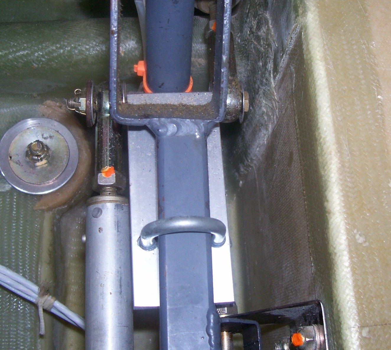
Hello Tim, Thanks for the pictures. I found picture 059 (see attached) to be
of particular interest.
Note that the laterally fixed cross bar between the control sticks in that
picture is round and has an adjustable aileron stop bracket (by means of a
through bolt) welded onto the bottom of the round cross bar. This bracket is
probably what Keith Miller was referring to in his posting on the subject of
aileron control stops.
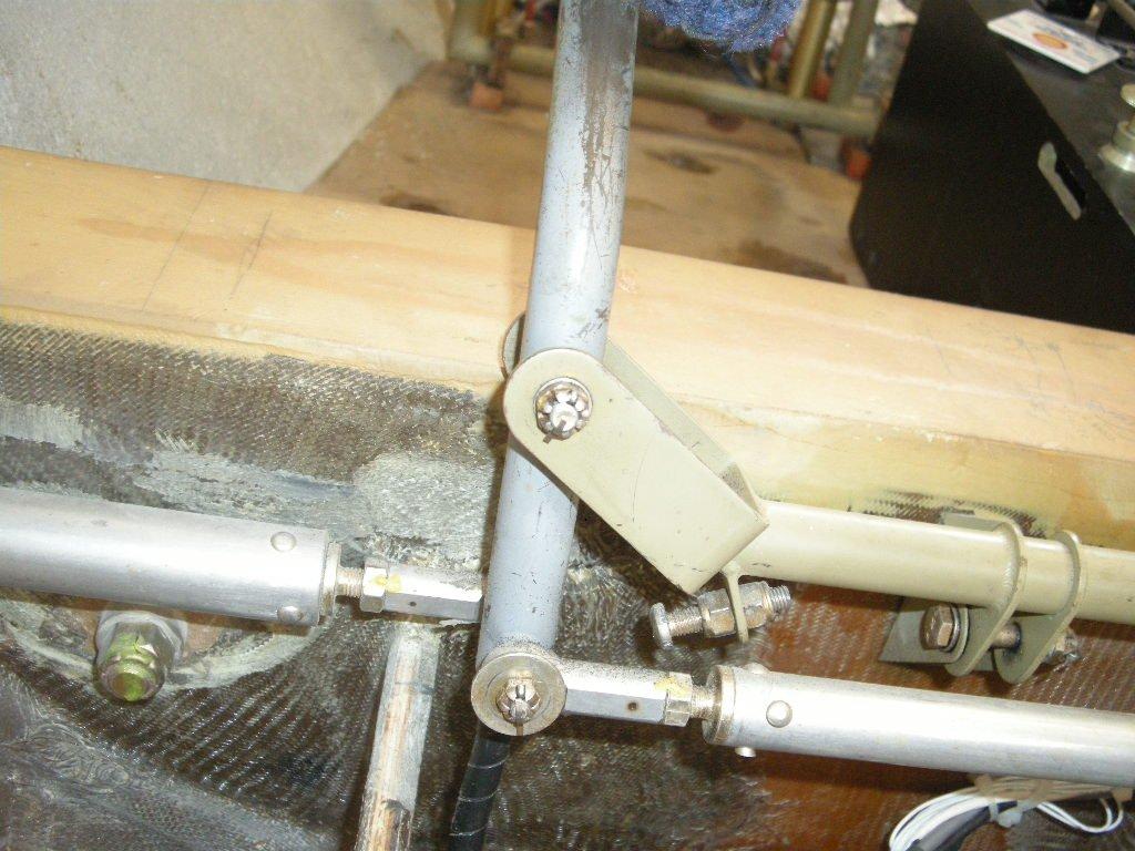
When you look at picture 0371 (also attached) you can see that the laterally
fixed cross bar has been changed (in my kit # 116) to a square configuration
and there is no adjustable aileron bracket welded onto it.
It also appears that the vertical position of the laterally fixed round
cross bar in picture 059 is higher than the laterally fixed square cross bar
in picture 0371 with relation to the wing spar mounting box. This would
result in the push rods going out to the ailerons also being higher in
picture 059 than in picture 0371.
Maybe this would account for the fact that Hans Christian found that the
holes in his wing ribs did not match the long aileron push rod vertical
position. Perhaps Tri-R made a change in the laterally fixed cross bar from
round to square and at the same time lowered the vertical position of the
laterally fixed cross bar. What say you Rich?
Also note the significant difference in the fore and aft vertical support
going to the wing spar mounting box in the two pictures. In picture 059 you
can see the exposed edge of the plywood core of this vertical support. In
picture 0371 you can see an extensive amount of fiber glass lay up entirely
covering this plywood core, which is presumably inside the fiber glass lay
up. This lay up was done at the factory as part of the fuselage quick build
feature by Bill Grote and his crew. (Bill are you still on the list? Anybody
have an email address for Bill?)
'OC' Baker Says: "The best investment we can make is the time and effort to
gather and understand knowledge."
PS: Tim, I noticed that you sent a copy of your 8/7/2010 email copied below
to the matronics aeroelectric-list rather than the matronics kis list. I
imagine that that puzzled a few of the aeroelectric-list readers. Do you
want to send your email again to the matronics kis list so that the archives
there are complete?
=============================================================
---
| | - The Matronics KIS-List Email Forum - | | | Use the List Feature Navigator to browse the many List utilities available such as the Email Subscriptions page, Archive Search & Download, 7-Day Browse, Chat, FAQ, Photoshare, and much more:
http://www.matronics.com/Navigator?KIS-List |
|
| Description: |
|
| Filesize: |
293.39 KB |
| Viewed: |
2243 Time(s) |
|
| Description: |
|
| Filesize: |
123.52 KB |
| Viewed: |
2243 Time(s) |
|
|
|
| Back to top |
|
 |
Keith.Miller(at)esa.int
Guest
|
| Posted: Sun Aug 08, 2010 11:24 pm Post subject: KIS TR-1 Control Stick Mounting |
|
|
OC


I can confirm that on my kit #079 has the fixed  cross bar with the welded

bracket for the aileron stop. This is also the  same cross over  bar that is

illustrated in the build manual  (which clearly shows this welded bracket ) .

Not sure why Rich would have changed this to the other design  as it looks

simple(Cheap) to make .  as for the position of the  aileron tubes  going out

to the wing , I also initially had the same problem as Hans ,  but  I then

mounted the two stick assembly brackets attached to the spar tunnel upside

down which lowered the assembly enough to provide the  correct clearance.


 Keith

|------------>

| From:      |

|------------>

  >------------------------------------------------------------------------------------------------------------------------------------------------------|

  |<bakerocb(at)cox.net>                                                                                                                                    |

  >------------------------------------------------------------------------------------------------------------------------------------------------------|

|------------>

| To:        |

|------------>

  >------------------------------------------------------------------------------------------------------------------------------------------------------|

  |"KIS-LIST, MATRONICS" <kis-list(at)matronics.com>                                                                                                        |

  >------------------------------------------------------------------------------------------------------------------------------------------------------|

|------------>

| Date:      |

|------------>

  >------------------------------------------------------------------------------------------------------------------------------------------------------|

  |08/08/2010 14:12                                                                                                                                      |

  >------------------------------------------------------------------------------------------------------------------------------------------------------|

|------------>

| Subject:   |

|------------>

  >------------------------------------------------------------------------------------------------------------------------------------------------------|

  |KIS TR-1 Control Stick Mounting                                                                                                             |

  >------------------------------------------------------------------------------------------------------------------------------------------------------|

|------------>

| Sent by:   |

|------------>

  >------------------------------------------------------------------------------------------------------------------------------------------------------|

  |owner-kis-list-server(at)matronics.com                                                                                                                   |

  >------------------------------------------------------------------------------------------------------------------------------------------------------|


8/8/2010


Hello Tim, Thanks for the pictures. I found picture 059 (see attached) to be

of particular interest.


Note that the laterally fixed cross bar between the control sticks in that

picture is round and has an adjustable aileron stop bracket (by means of a

through bolt) welded onto the bottom of the round cross bar. This bracket is

probably what Keith Miller was referring to in his posting on the subject of

aileron control stops.


When you look at picture 0371 (also attached) you can see that the laterally

fixed cross bar has been changed (in my kit # 116) to a square configuration

and there is no adjustable aileron bracket welded onto it.


It also appears that the vertical position of the laterally fixed round

cross bar in picture 059 is higher than the laterally fixed square cross bar

in picture 0371 with relation to the wing spar mounting box. This would

result in the push rods going out to the ailerons also being higher in

picture 059 than in picture 0371.


Maybe this would account for the fact that Hans Christian found that the

holes in his wing ribs did not match the long aileron push rod vertical

position. Perhaps Tri-R made a change in the laterally fixed cross bar from

round to square and at the same time lowered the vertical position of the

laterally fixed cross bar. What say you Rich?


Also note the significant difference in the fore and aft vertical support

going to the wing spar mounting box in the two pictures. In picture 059 you

can see the exposed edge of the plywood core of this vertical support. In

picture 0371 you can see an extensive amount of fiber glass lay up entirely

covering this plywood core, which is presumably inside the fiber glass lay

up. This  lay up was done at the factory as part of the fuselage quick build

feature by Bill Grote and his crew. (Bill are you still on the list? Anybody

have an email address for Bill?)


'OC' Baker Says: "The best investment we can make is the time and effort to

gather and understand knowledge."


PS: Tim, I noticed that you sent a copy of your 8/7/2010 email copied below

to the matronics aeroelectric-list rather than the matronics kis list. I

imagine that that puzzled a few of the aeroelectric-list readers. Do you

want to send your email again to the matronics kis list so that the archives

there are complete?


=============================================================


---
| | - The Matronics KIS-List Email Forum - | | | Use the List Feature Navigator to browse the many List utilities available such as the Email Subscriptions page, Archive Search & Download, 7-Day Browse, Chat, FAQ, Photoshare, and much more:
http://www.matronics.com/Navigator?KIS-List |
|
|
|
| Back to top |
|
|
|
|
You cannot post new topics in this forum
You cannot reply to topics in this forum
You cannot edit your posts in this forum
You cannot delete your posts in this forum
You cannot vote in polls in this forum
You cannot attach files in this forum
You can download files in this forum
|
Powered by phpBB © 2001, 2005 phpBB Group
|

