 |
Matronics Email Lists
Web Forum Interface to the Matronics Email Lists
|
| View previous topic :: View next topic |
| Author |
Message |
JLuckey(at)pacbell.net
Guest
|
 Posted: Wed Jun 27, 2012 9:23 am Post subject: Latching Relay Redux Posted: Wed Jun 27, 2012 9:23 am Post subject: Latching Relay Redux |
 |
|
Back in 2011 there was some discussion of new latching-type relay/contactors that might be suitable for use as master relays.


I remember at the time looking at the spec sheets & pricing of some of those devices and they seemed available & reasonably priced.


I google search earlier this week failed to turn-up any devices that were reasonably priced and they seemed to have huge lead times.


I want to consider using such a device but if they are difficult to get, I won’t bother.  Does anyone have a source(s) for such a device?


TIA


Jeff Luckey


       [quote][b]
| | - The Matronics AeroElectric-List Email Forum - | | | Use the List Feature Navigator to browse the many List utilities available such as the Email Subscriptions page, Archive Search & Download, 7-Day Browse, Chat, FAQ, Photoshare, and much more:
http://www.matronics.com/Navigator?AeroElectric-List |
|
|
|
| Back to top |
|
 |
nuckolls.bob(at)aeroelect
Guest
|
| Posted: Wed Jun 27, 2012 10:02 am Post subject: Latching Relay Redux |
|
|
At 12:21 PM 6/27/2012, you wrote:

Back in 2011 there was some discussion of new latching-type

relay/contactors that might be suitable for use as master relays.


I remember at the time looking at the spec sheets & pricing of some

of those devices and they seemed available & reasonably priced.


I google search earlier this week failed to turn-up any devices that

were reasonably priced and they seemed to have huge lead times.


I want to consider using such a device but if they are difficult to

get, I won't bother.  Does anyone have a source(s) for such a device?


   If your design incorporates this, or any other

   uniquely crafted product, you're presented with

   both 'spares' and 'unconventional operations'

   issues. If the design goal is to reduced energy

   consumption in the battery contactor, you could

   craft a duty-cycle controller that drops the

   contactor excitation to about 1/2 say 1 second

   after you energize it. More than enough to keep

   it closed yet drops heating (energy consuption)

   by 75% or so.


   Then you can use ANY contactor in the constellation

   of similar devices while. What's more, with a

   alternate feed path to an E-bus, risks to mission

   for failure of your energy conservation device are

   covered by the same Plan-B that covers main

   alternator failure. The airplane's controls are

   consistent with legacy philosophies and no new

   spares issues are created.


   Bob . . .
| | - The Matronics AeroElectric-List Email Forum - | | | Use the List Feature Navigator to browse the many List utilities available such as the Email Subscriptions page, Archive Search & Download, 7-Day Browse, Chat, FAQ, Photoshare, and much more:
http://www.matronics.com/Navigator?AeroElectric-List |
|
|
|
| Back to top |
|
|
JLuckey(at)pacbell.net
Guest
|
| Posted: Wed Jun 27, 2012 12:02 pm Post subject: Latching Relay Redux |
|
|
Bob,


All good points, many of which have been discussed on this forum.


I'm currently doing a more academic analysis (you know, when you are stuck

in traffic) as to how such devices might improve a system design (if at all)

but, if they are difficult to obtain then I think the point is moot.


BTW - a "pull & hold" circuit seems to me to be a non-starter - putting a

bunch of 'exotic' circuitry in the critical path of the coil circuit to

accomplish such a trivial task seems to me to be counter-productive.  If you

are counting milliamps then your system probably has bigger problems.

-Jeff


--
| | - The Matronics AeroElectric-List Email Forum - | | | Use the List Feature Navigator to browse the many List utilities available such as the Email Subscriptions page, Archive Search & Download, 7-Day Browse, Chat, FAQ, Photoshare, and much more:
http://www.matronics.com/Navigator?AeroElectric-List |
|
|
|
| Back to top |
|
|
nuckolls.bob(at)aeroelect
Guest
|
| Posted: Wed Jun 27, 2012 12:48 pm Post subject: Latching Relay Redux |
|
|
| Quote: | BTW - a "pull & hold" circuit seems to me to be a non-starter - putting a
bunch of 'exotic' circuitry in the critical path of the coil circuit to
accomplish such a trivial task seems to me to be counter-productive. If you
are counting milliamps then your system probably has bigger problems. |
That philosophy is core to this product from Tyco
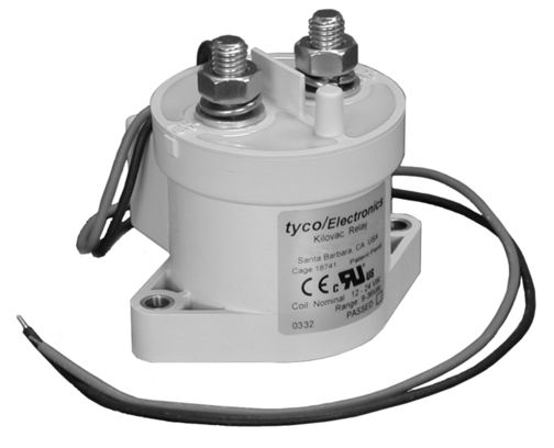
which not only offers a sealed atmosphere environment
for better high voltage handling but an after-engagement
duty-cycle managed for reduced power consumption. But
it's about a $135 device as I recall.
One of the drivers for installation of the E-bus was
to eliminate the 0.7A draw of a battery contactor
during alternator-out operations. That much current
would run several radios . . . but might seriously
impact a design goal for battery-only endurance to
exceed fuel endurance. Trivial task? It's a matter
of degree . . .
Exotic? About $6 worth of Radio Shack parts
will do it and it doesn't increase risks. But
if one has a Rotax 18A or SD-8 excited airplane
the wasted watts become more critical than when
you've got 60A alternator with 40 to burn. So
one could choose to achieve similar performance
with a plain vanilla contactor and DIY duty-cycle
management.
Hardware capable of very fancy footwork is becoming
less expensive while consuming less power. The things
one could put in a 25 year-old VariEz lit up with
an SD-8 were very limited . . . not so much today.
It's all inter-related and as mentioned earlier,
related to mission, hardware, full up vs.
endurance loads, battery sizes and PM protocols.
So if latching battery contactor is more a
attractive than a duty-cycle managed device, you
are ultimately responsible for the formulation
of design goals and techniques used to meet them.
The basket of bits-and-pieces with which the big
picture is painted is huge . . .
Bob . . . [quote][b]
| | - The Matronics AeroElectric-List Email Forum - | | | Use the List Feature Navigator to browse the many List utilities available such as the Email Subscriptions page, Archive Search & Download, 7-Day Browse, Chat, FAQ, Photoshare, and much more:
http://www.matronics.com/Navigator?AeroElectric-List |
|
|
|
| Back to top |
|
|
user9253
Joined: 28 Mar 2008
Posts: 1908
Location: Riley TWP Michigan
|
| Posted: Thu Jun 28, 2012 7:51 am Post subject: Re: Latching Relay Redux |
|
|
Attached is an untried circuit to reduce contactor current using PWM.

The TC648 costs less than $2.  It will start up at 100 percent duty cycle to pull in the master contactor.  Then it will hold with PWM at reduced current.  The progressive transfer type switch will normally be operated in the center position but can be full up to bypass the PWM circuit.

http://ww1.microchip.com/downloads/en/DeviceDoc/21755b.pdf

Joe
| | - The Matronics AeroElectric-List Email Forum - | | | Use the List Feature Navigator to browse the many List utilities available such as the Email Subscriptions page, Archive Search & Download, 7-Day Browse, Chat, FAQ, Photoshare, and much more:
http://www.matronics.com/Navigator?AeroElectric-List |
|
| Description: |
|

Download |
| Filename: |
Contactor PWM.pdf |
| Filesize: |
6.8 KB |
| Downloaded: |
450 Time(s) |
_________________
Joe Gores |
|
| Back to top |
|
|
JLuckey(at)pacbell.net
Guest
|
| Posted: Thu Jun 28, 2012 8:51 am Post subject: Latching Relay Redux |
|
|
Joe


As I have mentioned in previous posts, I'm not a big fan of adding complex

circuitry to the coil circuit of the master contactor.  I think it makes the

system less reliable for very little benefit.


However, I do like the way the switch is wired in that schematic with the

bypass circuit.


-Jeff


--
| | - The Matronics AeroElectric-List Email Forum - | | | Use the List Feature Navigator to browse the many List utilities available such as the Email Subscriptions page, Archive Search & Download, 7-Day Browse, Chat, FAQ, Photoshare, and much more:
http://www.matronics.com/Navigator?AeroElectric-List |
|
|
|
| Back to top |
|
|
bobmeyers(at)meyersfamily
Guest
|
| Posted: Thu Jun 28, 2012 10:44 am Post subject: Latching Relay Redux |
|
|
Just a note,


I got one of these Tyco EV200 for use in my Sonex with an Aerovee Volkswagen conversion with a 20 amp alternator.  I got mine on eBay for about $60 three years ago and they seem to be in that same ballpark today on ebay.

I went from a measured contractor draw of 0.7A to 0.13A.  The product is very robust and the amperage savings can almost operate my EFIS.

 Bob Meyers


Flight testing completed, now flying Sonex N982SX. Web Site Index http://N982SX.com


 [quote][b]
| | - The Matronics AeroElectric-List Email Forum - | | | Use the List Feature Navigator to browse the many List utilities available such as the Email Subscriptions page, Archive Search & Download, 7-Day Browse, Chat, FAQ, Photoshare, and much more:
http://www.matronics.com/Navigator?AeroElectric-List |
|
|
|
| Back to top |
|
|
Tundra10
Joined: 14 Jun 2010
Posts: 102
Location: Scarborough, Ontario
|
| Posted: Tue Jul 03, 2012 1:59 pm Post subject: Latching Relay Redux |
|
|
Joe,
Not shown in your diagram is the spike shunting diode on the contactor
to protect the FET.
Jeff Page
Dream Aircraft Tundra #10
| Quote: | Time: 08:51:57 AM PST US
Subject: Re: Latching Relay Redux
From: "user9253" <fran4sew(at)banyanol.com>
Attached is an untried circuit to reduce contactor current using PWM.
The TC648 costs less than $2. It will start up at 100 percent duty
cycle to pull
in the master contactor. Then it will hold with PWM at reduced current. The
progressive transfer type switch will normally be operated in the
center position
but can be full up to bypass the PWM circuit.
Joe
--------
Joe Gores
|
| | - The Matronics AeroElectric-List Email Forum - | | | Use the List Feature Navigator to browse the many List utilities available such as the Email Subscriptions page, Archive Search & Download, 7-Day Browse, Chat, FAQ, Photoshare, and much more:
http://www.matronics.com/Navigator?AeroElectric-List |
|
|
|
| Back to top |
|
|
user9253
Joined: 28 Mar 2008
Posts: 1908
Location: Riley TWP Michigan
|
| Posted: Tue Jul 03, 2012 6:38 pm Post subject: Re: Latching Relay Redux |
|
|
Good point, Jeff.  My mistake.  I added a diode.  Keep in mind that I have never built this circuit.  So there is no guarantee that it will work.  The TC648 operating frequency of 30HZ can possibly be increased with a smaller value of C5.   The TC648 is designed for use with fan motors which have inertia.  The off time period is not a concern with fans but is a concern with contactors that could drop out.  If my math is correct, the off time period at 25 percent duty cycle is 25ms.  This might be too long and allow the contactor to drop out.  The diode will delay the drop out.  Will a capacitor in parallel with the contactor coil also help to delay the drop out?

Joe
| | - The Matronics AeroElectric-List Email Forum - | | | Use the List Feature Navigator to browse the many List utilities available such as the Email Subscriptions page, Archive Search & Download, 7-Day Browse, Chat, FAQ, Photoshare, and much more:
http://www.matronics.com/Navigator?AeroElectric-List |
|
| Description: |
|
Download |
| Filename: |
Contactor PWM.pdf |
| Filesize: |
18.88 KB |
| Downloaded: |
917 Time(s) |
_________________
Joe Gores |
|
| Back to top |
|
|
Tundra10
Joined: 14 Jun 2010
Posts: 102
Location: Scarborough, Ontario
|
| Posted: Tue Jul 03, 2012 7:12 pm Post subject: Re: Latching Relay Redux |
|
|
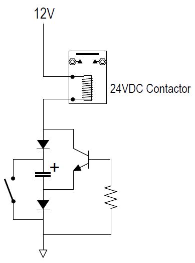
Has anyone considered this voltage doubling circuit ?  It was the Circuit Cellar EQ question in Issue 248 March 2011.


The theory behind the circuit is that while the contactor is off, the capacitor charges to 12V.  When the switch is turned on, the positive of the capacitor is 0V, so the negative side becomes -12V.  The transistor now conducts, applying 12+12=24V across the contactor coil, closing it.  The capacitor quickly discharges and the transistor switches off, leaving 12V across the contactor coil.  12V is probably enough to keep the contactor closed and at half the current of a 12V contactor.


Once the flight has begun, the failure mode is down to the contactor, the switch and one diode, which is the same component count as the standard circuit (The spike shunt diode is not required for this circuit, since the current from the coil serves to charge the capacitor faster).


The article did not propose values for the components, so it is quite possible that the capacitor would need to be impractically large.


Jeff Page

Dream Aircraft Tundra #10
| | - The Matronics AeroElectric-List Email Forum - | | | Use the List Feature Navigator to browse the many List utilities available such as the Email Subscriptions page, Archive Search & Download, 7-Day Browse, Chat, FAQ, Photoshare, and much more:
http://www.matronics.com/Navigator?AeroElectric-List |
|
| Description: |
|
| Filesize: |
21.72 KB |
| Viewed: |
10762 Time(s) |
|
|
|
| Back to top |
|
|
user9253
Joined: 28 Mar 2008
Posts: 1908
Location: Riley TWP Michigan
|
| Posted: Mon Jul 30, 2012 6:07 pm Post subject: Re: Latching Relay Redux |
|
|
I received this email today from Chuck (quoted below) in reference to my circuit "Contactor PWM.pdf " to reduce contactor holding current.
http://forums.matronics.com/download.php?id=32370
| Quote: | Hello Joe
I built the circuit with one change. I replaced R1 with an adjustable 0-25k ohm pot. Works great, just dial in the PWM for the right duty cycle with R1 for the particular contactor being used.
Thanks Chuck |
| | - The Matronics AeroElectric-List Email Forum - | | | Use the List Feature Navigator to browse the many List utilities available such as the Email Subscriptions page, Archive Search & Download, 7-Day Browse, Chat, FAQ, Photoshare, and much more:
http://www.matronics.com/Navigator?AeroElectric-List |
|
_________________
Joe Gores |
|
| Back to top |
|
|
nuckolls.bob(at)aeroelect
Guest
|
| Posted: Wed Aug 01, 2012 5:03 am Post subject: Latching Relay Redux |
|
|
At 09:07 PM 7/30/2012, you wrote:
| Quote: |
I received this email today from Chuck (quoted below) in reference
to my circuit "Contactor PWM.pdf " to reduce contactor holding current.
http://forums.matronics.com/download.php?id=32370
> Hello Joe
> I built the circuit with one change. I replaced R1 with an
adjustable 0-25k ohm pot. Works great, just dial in the PWM for the
right duty cycle with R1 for the particular contactor being used.
> Thanks Chuck
|
I recommend that the power saving duty cycle
be set for not less than 50%. This cuts average
voltage to contactor by 50% . . . hence average
current by 50% and total power dissipated by
75%.
While a 12v contactor will stay energized at
voltages of 2v or below, you want to make sure
that the contactor stays closed down to battery
end of life at 10.5 volts or so. 50% at 14 volts
with alternator running gives you 7 volts to hold
the contactor . . . 10.5 translates to 5.25 volts
or thereabouts . . . probably as low as you want
to go. 75% reduction in lost energy is pretty
substantial if you're in a battery-only operational
mode . . . or struggling to make the most of an
8A alternator.
Bob . . .
Bob . . .
| | - The Matronics AeroElectric-List Email Forum - | | | Use the List Feature Navigator to browse the many List utilities available such as the Email Subscriptions page, Archive Search & Download, 7-Day Browse, Chat, FAQ, Photoshare, and much more:
http://www.matronics.com/Navigator?AeroElectric-List |
|
|
|
| Back to top |
|
|
klehman(at)albedo.net
Guest
|
| Posted: Wed Aug 01, 2012 7:22 am Post subject: Latching Relay Redux |
|
|
Is that 75% power reduction correct??
I would have guessed that a 50% duty cycle gave full voltage and full
current for 50% of the time in a pulsed resistance circuit resulting in
a 50% power reduction. Not sure about an inductive coil contactor though.
Just asking but intuitively I would not have averaged the voltage and
applied the I squared power calculation to this.
Ken
On 01/08/2012 9:02 AM, Robert L. Nuckolls, III wrote:
| Quote: |
<nuckolls.bob(at)aeroelectric.com>
At 09:07 PM 7/30/2012, you wrote:
>
> <fran4sew(at)banyanol.com>
>
> I received this email today from Chuck (quoted below) in reference to
> my circuit "Contactor PWM.pdf " to reduce contactor holding current.
> http://forums.matronics.com/download.php?id=32370
>
> > Hello Joe
> > I built the circuit with one change. I replaced R1 with an
> adjustable 0-25k ohm pot. Works great, just dial in the PWM for the
> right duty cycle with R1 for the particular contactor being used.
> > Thanks Chuck
I recommend that the power saving duty cycle
be set for not less than 50%. This cuts average
voltage to contactor by 50% . . . hence average
current by 50% and total power dissipated by
75%.
While a 12v contactor will stay energized at
voltages of 2v or below, you want to make sure
that the contactor stays closed down to battery
end of life at 10.5 volts or so. 50% at 14 volts
with alternator running gives you 7 volts to hold
the contactor . . . 10.5 translates to 5.25 volts
or thereabouts . . . probably as low as you want
to go. 75% reduction in lost energy is pretty
substantial if you're in a battery-only operational
mode . . . or struggling to make the most of an
8A alternator.
Bob . . .
|
| | - The Matronics AeroElectric-List Email Forum - | | | Use the List Feature Navigator to browse the many List utilities available such as the Email Subscriptions page, Archive Search & Download, 7-Day Browse, Chat, FAQ, Photoshare, and much more:
http://www.matronics.com/Navigator?AeroElectric-List |
|
|
|
| Back to top |
|
|
nuckolls.bob(at)aeroelect
Guest
|
| Posted: Wed Aug 01, 2012 9:32 am Post subject: Latching Relay Redux |
|
|
At 10:20 AM 8/1/2012, you wrote:
--> AeroElectric-List message posted by: Ken <klehman(at)albedo.net>
Is that 75% power reduction correct??
I would have guessed that a 50% duty cycle gave full voltage and full current for 50% of the time in a pulsed resistance circuit resulting in a 50% power reduction. Not sure about an inductive coil contactor though.
Just asking but intuitively I would not have averaged the voltage and applied the I squared power calculation to this.
-----------
Excellent question . . . and yes, consideration of
contactor inductance paralleled with a diode
is critical to the analysis.
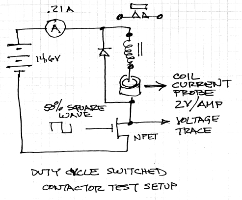
When to the bench and set this up:
[img]cid:.0[/img]
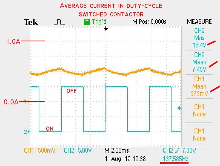
This test setup produced the following data:
[img]cid:.1[/img]
If I go to 100% duty cycle, this El Cheeso,
Stancore/RBM contactor draws 0.9 amps 14.6 volts.
Dynamically, the coil current (Yellow trace) shows
some ripple at the switching frequency but averages
just under 0.5 Amp.
In the mean time, the power supply is showing a
load of just 0.21 amps or about 25% of the full-on
current draw.
If I put a 15 ohm resistor in place of the\
contactor, the 100% current goes to the expected
1 amp. At 50% duty cycle, the peak current is still
1 amp with average current falling to the predicted
0.5A . . . hence 50% duty cycle produces only 50%
reduction in power in the resistive circuit.
The L/R time constant of the inductive circuit
prevents achievement of full current during limited
on-time. The diode prevents current from falling
to zero during off-time.
After one hour, the outside temperature of the
contactor was not too hot to sustained touch . . .
Waayyy cooler than contactor operatied at 100%.
Bob . . .
| | - The Matronics AeroElectric-List Email Forum - | | | Use the List Feature Navigator to browse the many List utilities available such as the Email Subscriptions page, Archive Search & Download, 7-Day Browse, Chat, FAQ, Photoshare, and much more:
http://www.matronics.com/Navigator?AeroElectric-List |
|
| Description: |
|
| Filesize: |
106.91 KB |
| Viewed: |
10631 Time(s) |
|
| Description: |
|
| Filesize: |
161.62 KB |
| Viewed: |
10631 Time(s) |
|
|
|
| Back to top |
|
|
nuckolls.bob(at)aeroelect
Guest
|
| Posted: Wed Aug 01, 2012 7:33 pm Post subject: Latching Relay Redux |
|
|
At 12:30 PM 8/1/2012, you wrote:
| Quote: | At 10:20 AM 8/1/2012, you wrote:
Is that 75% power reduction correct??
I would have guessed that a 50% duty cycle gave full voltage and
full current for 50% of the time in a pulsed resistance circuit
resulting in a 50% power reduction. Not sure about an inductive coil
contactor though.
Just asking but intuitively I would not have averaged the voltage
and applied the I squared power calculation to this.
-----------
|
P.S. just for grins, I thermocoupled the contactor
and let it stabilize for over an hour. Got a 120
F shell at 50% duty cycle for a 40F rise.
Let it run 100% duty cycle to stabilization and
got a 180F shell temperature for a 100F rise.
At that temperature, the 100% duty cycle current
draw was down to .6 amps from the cold start at
.9 amps. This copper temperature coefficient of
resistance rise in coil accounts for the less
than 4x temperature rise for 4x the dissipated power . . .
This means that a cooler contactor uses the power
you supply it more efficiently by running a
lower winding resistance. I.e. ampere turns
of magnetic flux that is more proportional to
applied voltage because the coil is cooler.
By the way, here's one approach to fabricating
a "contactor cooler" . . .
http://tinyurl.com/bolkoyc
On power up, both capacitors are discharged.
The 10uf holds down on the comparator pins
2,6 for about 100 milliseconds thus holding
the output pin 3 HI, turning the FED on hard
and energizing the contactor with full voltage.
The 10uF charges up in 100-200 milliseconds
thus allowing the 555 to 'hum' at about 200Hz
and 50% duty cycle. The diode and RC network
across the contactor coil should be mounted
right to the contactor terminals. All other
components can be remotely located but close
proximity to contactor is best.
Bob . . .
| | - The Matronics AeroElectric-List Email Forum - | | | Use the List Feature Navigator to browse the many List utilities available such as the Email Subscriptions page, Archive Search & Download, 7-Day Browse, Chat, FAQ, Photoshare, and much more:
http://www.matronics.com/Navigator?AeroElectric-List |
|
|
|
| Back to top |
|
|
|
|
You cannot post new topics in this forum
You cannot reply to topics in this forum
You cannot edit your posts in this forum
You cannot delete your posts in this forum
You cannot vote in polls in this forum
You cannot attach files in this forum
You can download files in this forum
|
Powered by phpBB © 2001, 2005 phpBB Group
|

