 |
Matronics Email Lists
Web Forum Interface to the Matronics Email Lists
|
| View previous topic :: View next topic |
| Author |
Message |
ceengland7(at)gmail.com
Guest
|
 Posted: Sat Jul 04, 2015 12:21 pm Post subject: Diode Reverse Voltage Leak or Invalid Measurement Setup? Posted: Sat Jul 04, 2015 12:21 pm Post subject: Diode Reverse Voltage Leak or Invalid Measurement Setup? |
 |
|
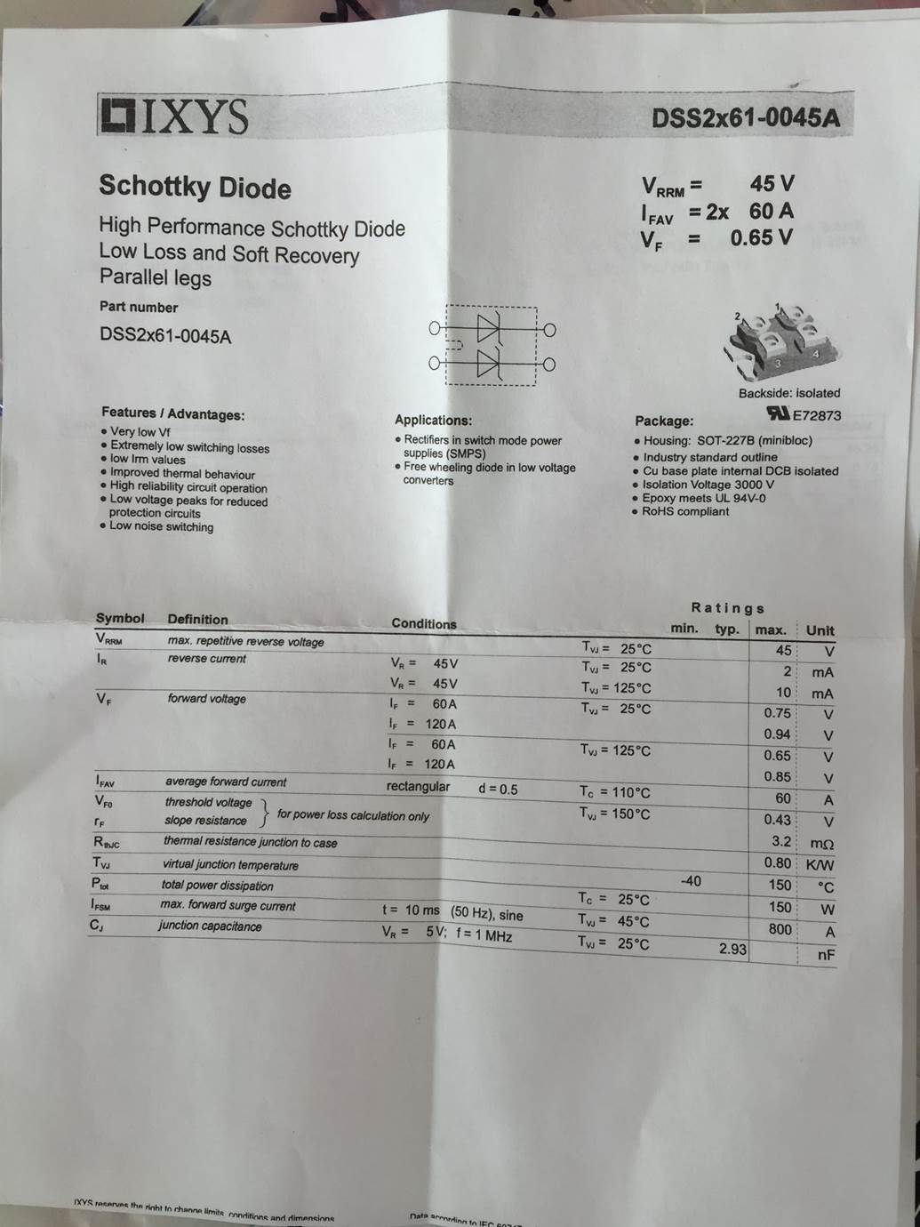
Not really relevant to your question, but the spec sheet has the wrong symbol for the diodes (zener instead of Schottky).
In general, if you leave the ground side of a circuit floating and measure from the floating ground to the actual supply ground, you will see some voltage (in some cases, the full voltage of the supply). For your voltage test of the diode pack, try inserting a 12V load (light, etc) in series with the diode, connected from the diode anode (your red test lead point) to the battery ground terminal. Measure voltage on the same points shown in your pic. I'll bet that the load (light) won't illuminate, and you won't see any voltage. All semiconductors have some leakage, but won't supply significant current because the leakage is so low. Your spec sheet says IsubR is 2 mA at 45 volts, so would be much lower at 12 volts.
My terminology probably isn't precise (I was a repair grunt; not an engineer), but hopefully the idea is still there.
Charlie
On Sat, Jul 4, 2015 at 2:03 PM, Valin Thorn <valin(at)starflight.aero (valin(at)starflight.aero)> wrote:
| Quote: |
Hello,
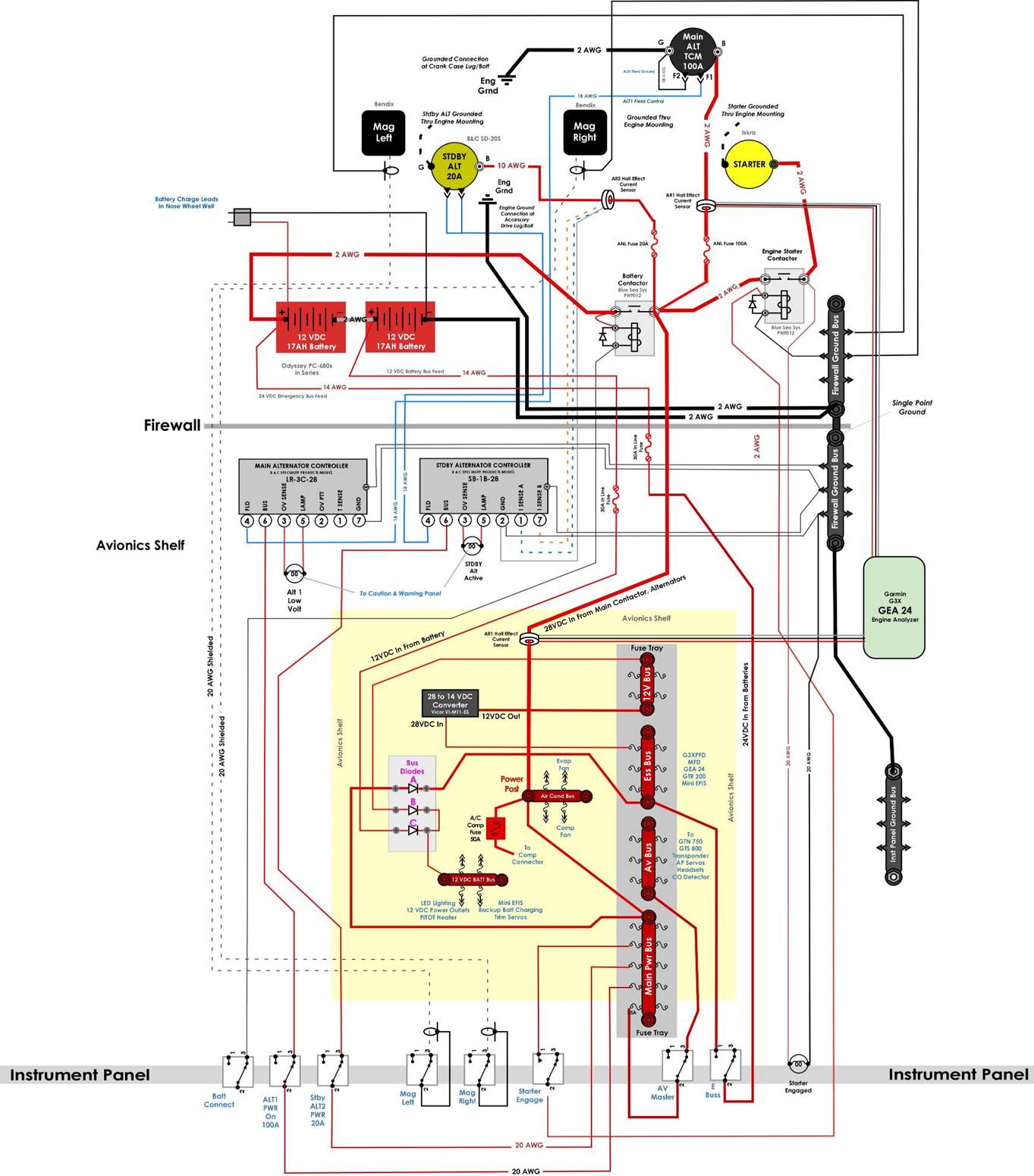
We’re getting set to do power on testing of our electrical system and avionics. We’re using the (Bob’s) Z-12 power grid at 28 VDC with a 12 VDC bus and 12VDC hot battery bus.
We have schottkey diodes isolating the various buses.
With the positive battery terminal connected and the 12 VDC hot battery lead connected, but NOT the battery ground to the single point ground, I checked the voltage at various points and saw the 12+ VDC where it should be but was surprised to measure about 3.5 VDC on the Main Bus and even the Ground Bus.
The meter set up was with the VOM meter ground lead to the battery ground (not connected to the airplane’s ground bus) and then the positive prove to the various measurement locations.
At first I thought we must have a pin out wrong in a connector somewhere – and maybe we do. After some trouble shooting, I was able to determine that the voltage seems to be leaking in reverse past the diode from the 12 VDC Hot Batt Bus to the 12VDC Bus and then through the 24 to 12 VDC converter to the Main Bus. But somehow, when I put the meter’s positive probe on the ground bus, it also shows 3.5 VDC. So not even sure this is a valid way to test that I’m using…
Here’s our Power Grid. Sorry Bob that it is in my pictogram format… The anode side of Diode B is where I’m seeing 3.5 VDC with 12VDC on the cathode side, as expected, coming from the hot battery bus.
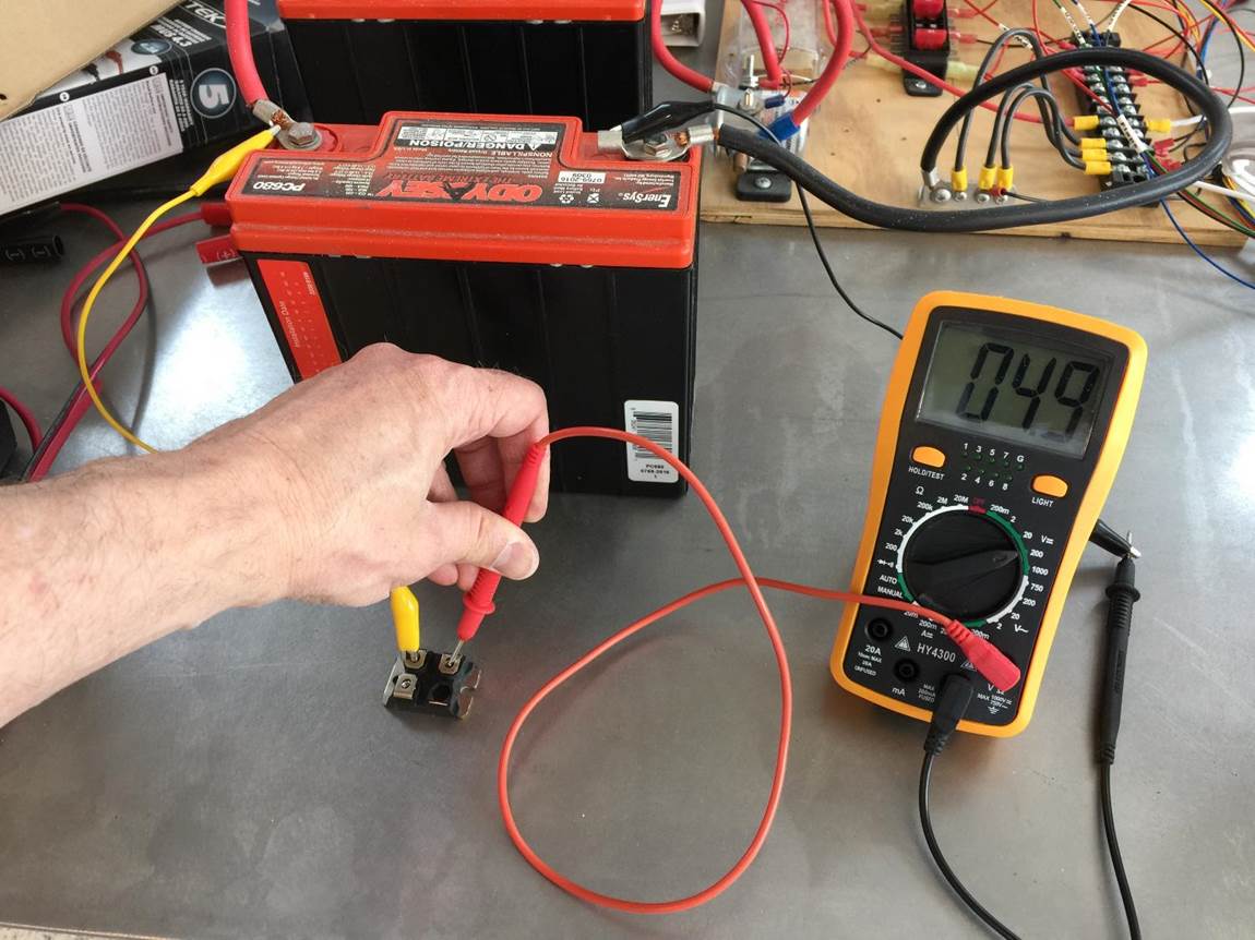
I did a test of a spare diode of the same model on the bench with a single 12 VDC battery and measure 4.9 VDC on the anode side of the diode with the cathode connected to the battery’s positive terminal. See photo below.
My questions.
1. Is this even a valid voltage measurement setup? Is this real? If both the positive and negative side of the electrical system are showing 3.5 VDC relative to the unattached battery ground, then there is no electrical potential difference/voltage between them…
2. Are these the wrong diodes for this application? (spec sheet attached)
3. What should I do?
I’d sure appreciate some help with this… Oh, and Happy Independence Day!
Thanks!
Valin
(Confused)
[img]cid:image004.jpg(at)01D0B659.C30873C0[/img]
[img]cid:image006.jpg(at)01D0B659.C30873C0[/img]
[img]cid:image008.jpg(at)01D0B659.C30873C0[/img]
|
| | - The Matronics AeroElectric-List Email Forum - | | | Use the List Feature Navigator to browse the many List utilities available such as the Email Subscriptions page, Archive Search & Download, 7-Day Browse, Chat, FAQ, Photoshare, and much more:
http://www.matronics.com/Navigator?AeroElectric-List |
|
| Description: |
|
| Filesize: |
208.01 KB |
| Viewed: |
1810 Time(s) |
|
| Description: |
|
| Filesize: |
115.24 KB |
| Viewed: |
1810 Time(s) |
|
| Description: |
|
| Filesize: |
119.45 KB |
| Viewed: |
1810 Time(s) |
|
|
|
| Back to top |
|
 |
Eric M. Jones

Joined: 10 Jan 2006
Posts: 565
Location: Massachusetts
|
| Posted: Sun Jul 05, 2015 5:57 am Post subject: Re: Diode Reverse Voltage Leak or Invalid Measurement Setup |
|
|
This is the Schottky diode that I sell with an appropriate heat sink, and it's a great part. You could have contacted me, but this is a general interest anyway, so an answer helps everyone.


All standard voltmeters have a built-in load. This is as it should be. If they did not, then nothing would make much sense. For special purposes, voltmeters can be built with arbitrarily high resistance (or a tiny load, called impedance in meters, etc.), but they all still have some load.


All electronic parts, even relays and switches, have "leakage". Insulation can still be measured in ohms, no matter how good, (millions and billions of ohms...)


So if you built a simple switch with nearly perfect insulation and applied a voltage to it, a voltmeter with infinite ohms resistance would still measure a voltage "through" the switch...whether or not the switch was on or off! That's why voltages are not measured through switches, relays, and any other parts.


I note this in some of my literature, that a voltage measurement without a load will give meaningless results. A Schottky diode has a very low Vf forward voltage drop (lower than P-N diodes). This saves power, but the Schottky also has a greater reverse current "leakage". The reverse current typically won't leak enough power to light even the smallest LED, but some builders worry that this is a defect.


It really isn't. It's just reality.


For those who are mystified by electrons. Check the attached.
| | - The Matronics AeroElectric-List Email Forum - | | | Use the List Feature Navigator to browse the many List utilities available such as the Email Subscriptions page, Archive Search & Download, 7-Day Browse, Chat, FAQ, Photoshare, and much more:
http://www.matronics.com/Navigator?AeroElectric-List |
|
| Description: |
|

Download |
| Filename: |
Dabbling with Electricity.pdf |
| Filesize: |
248.25 KB |
| Downloaded: |
217 Time(s) |
_________________
Eric M. Jones
www.PerihelionDesign.com
113 Brentwood Drive
Southbridge, MA 01550
(508) 764-2072
emjones(at)charter.net |
|
| Back to top |
|
|
|
|
You cannot post new topics in this forum
You cannot reply to topics in this forum
You cannot edit your posts in this forum
You cannot delete your posts in this forum
You cannot vote in polls in this forum
You cannot attach files in this forum
You can download files in this forum
|
Powered by phpBB © 2001, 2005 phpBB Group
|

