 |
Matronics Email Lists
Web Forum Interface to the Matronics Email Lists
|
| View previous topic :: View next topic |
| Author |
Message |
philperry9
Joined: 23 Nov 2011
Posts: 379
|
 Posted: Tue Apr 04, 2017 11:49 am Post subject: LSE Plasma III - Timing Posted: Tue Apr 04, 2017 11:49 am Post subject: LSE Plasma III - Timing |
 |
|
Closing in on the big day. Â The big ole girl has been weighed and the last pesky oil leak mystery has finally been solved.
I need to double check the timing on my LSE Plasma III ignition to confirm the timing is still within specs since I received the engine from Aerosport Power. I've read the LSE documents regarding timing the system, but I still have questions about the process.
Does anyone have a link to a website that describes the process to checkout the installation? Perhaps it can fill in a few gaps I have with the documentation.
Thanks
Phil
| | - The Matronics RV10-List Email Forum - | | | Use the List Feature Navigator to browse the many List utilities available such as the Email Subscriptions page, Archive Search & Download, 7-Day Browse, Chat, FAQ, Photoshare, and much more:
http://www.matronics.com/Navigator?RV10-List |
|
|
|
| Back to top |
|
 |
rvdave
Joined: 24 Jan 2009
Posts: 191
|
| Posted: Fri Apr 14, 2017 4:58 am Post subject: Re: LSE Plasma III - Timing |
|
|
Did you ever find a procedure for verifying timing? Almost to that point and want to be ready.
| | - The Matronics RV10-List Email Forum - | | | Use the List Feature Navigator to browse the many List utilities available such as the Email Subscriptions page, Archive Search & Download, 7-Day Browse, Chat, FAQ, Photoshare, and much more:
http://www.matronics.com/Navigator?RV10-List |
|
_________________
Dave Ford
Cadillac, MI |
|
| Back to top |
|
|
philperry9
Joined: 23 Nov 2011
Posts: 379
|
| Posted: Fri Apr 14, 2017 6:15 am Post subject: LSE Plasma III - Timing |
|
|
I did. It wasn't as confusing as I thought it would be. I will try and type something up and send it out in the next day or so.
Pretty straight forward. The most difficult part was finding/marking TDC for each coil.
Sent from my iPhone
| Quote: | On Apr 14, 2017, at 7:58 AM, rvdave <rv610dave(at)gmail.com> wrote:
Did you ever find a procedure for verifying timing? Almost to that point and want to be ready.
--------
Dave Ford
RV6 for sale
RV10 building
Cadillac, MI
Read this topic online here:
http://forums.matronics.com/viewtopic.php?p=468381#468381
|
| | - The Matronics RV10-List Email Forum - | | | Use the List Feature Navigator to browse the many List utilities available such as the Email Subscriptions page, Archive Search & Download, 7-Day Browse, Chat, FAQ, Photoshare, and much more:
http://www.matronics.com/Navigator?RV10-List |
|
|
|
| Back to top |
|
|
rvdave
Joined: 24 Jan 2009
Posts: 191
|
| Posted: Fri Apr 14, 2017 6:41 am Post subject: Re: LSE Plasma III - Timing |
|
|
Great, thanks
| | - The Matronics RV10-List Email Forum - | | | Use the List Feature Navigator to browse the many List utilities available such as the Email Subscriptions page, Archive Search & Download, 7-Day Browse, Chat, FAQ, Photoshare, and much more:
http://www.matronics.com/Navigator?RV10-List |
|
_________________
Dave Ford
Cadillac, MI |
|
| Back to top |
|
|
philperry9
Joined: 23 Nov 2011
Posts: 379
|
| Posted: Fri Apr 14, 2017 12:50 pm Post subject: LSE Plasma III - Timing |
|
|
Here's how I checked the timing on the LSE Plasma III. Â The most difficult part was locating TDC on the flywheel for each of the coils.
1) To start the process, you can put Cyl #1 on TDC of the compression stroke. Â You can locate TDC one of two ways, first there is a hole in the starter and a stamp on (the front of) your flywheel showing TDC 1. Â You can align the TDC 1 stamp to point directly at the hole on the starter. Â The second method is look on the backside of the flywheel and you will see the same TDC 1 stamp. Â The line on that stamp should be aligned with the top of the crankcase split.
NOTE: Since the engine will be running, you will check all Plasma III timings from the backside of the flywheel.
2) Now that you know where TDC is for cylinder #1 (really for the coils attached to 1 & 2), you need to segment the flywheel into equal 3rd.  This will allow you to locate TDC for the coils serving 3&4 and 5&6. That's the challenging part.
I took a long piece of blue painters tape and, starting at the TDC 1 mark we identified earlier, I pulled it around the flywheel laying it on the teeth. Then when it wrapped back up around to TDC 1 again, I marked it and cut it.  That gave me the full circumference of the teeth on the fly wheel.  I peeled the tape off and stuck it to a table.  The I used a ruler and marker to segment it in to 3rds.
Then I put the tape back on the flywheel again being careful to start the tape on TDC 1 again and wrapping it around.  The marks on the tape were transferred over to the flywheel.  I now know where TDC exist for Coils 1&2, Coils 3&4, and Coils 5&6.  (If TDC 1 is 0º then the next third over would be 120º and the next third over would be 240º before another third passes and we're back to 0º). Hopefully that makes sense.
3) Now the next step is to figure out how much advance we should be seeing at the time of ignition.  If you look in your LSE manual, there is a recommendation from them depending on the manufacturers suggested timing (stamped on your data plate).  I have 9:1 pistons and Aerosport Power recommends a 20º advance on the Mags.  If I look at the LSE manual, I can see that I should have 35º advance  +/- 2º (with the manifold pressure line connected) and 16º +/- 2º with the manifold pressure line disconnected.  Those are the metrics we are looking for.
4) Now we need to mark 16º and 35º advance of TDC on the backside of the flywheel.  We will have to add them for each of the TDC marks we put on the backside of the flywheel.
Using a piece of tape and the existing stampings on the backside of my flywheel for TDC, 20, 23, and 25, I made my own measurement tool to extrapolate where 16º and 35º would be prior to TDC. Then I measured it off for each of the TDC markings on my flywheel.  I put a mark at 16 and another at 35.  You want these marks to contrast really well since you're going to be looking for them with a timing light.
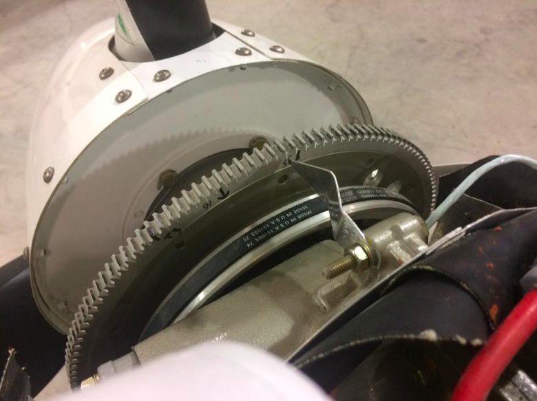
5) Once all the marks are made, you need to make a pointer to show where the crankcase split is relative to the marks. The pointer needs to be long enough to get right behind the flywheel to reduce error (since you're going to be standing off to the side looking at it).  Here's a photo of the pointer I made. I also tipped it with a red marker to make it easier to see. You can bend your pointer to align with the crankcase split.
[img]cid:ii_15b6e2b83fdb8d02[/img]
Now that your marks are made and your pointer is setup, you just have to check it.  You'll need a regular old induction timing light.  (IE: Not one of the new fancy ones with the computer dial on it, etc. Just a light that will pop when there is a spark detected.)  I ran mine in the sunlight and it was very difficult to see and I feel like it was a little more risk than I really wanted to take because I had to get the light right up there close to see it.  Shade or late evening would be even better.
The test should be performed between 600-900 RPM according to LSE. I chose 800 because the engine seems really happy and smooth idling there.
The first thing you want to check is the timing with the manifold pressure line connected.  Put your induction coupler over the spark plug lead on #1 or #2 (doesn't matter they're both attached to the same coil) and shoot the light at the pointer. You should see your mark for 35.
Then slip it over to the spark plug lead for #3 or #4 and shoot it again. You should see the other 35º mark.
Then slip it over to the spark plug lead for #5 or #6 and shoot it again.  Once again you should see the 35º mark.
Thats good, everything is right. Now we need to check it with the manifold pressure disconnected.  I have my MP going to the manifold with the oil pressure and fuel pressure sensors on it. For me, disconnecting MP is as simple as pulling off a rubber hose at that manifold. But somehow you need to pull the MP from the electronic ignition box. Â
When you do pull it, the engine will change in sound. LSE says it will stumble a bit, but I thought it still ran pretty well; just changed the sound a bit.
While your lead is still on 5/6, shoot it and you should see 16º.
Switch over to 3/4 and shoot it. You should see 16º.
Switch over to 1/2 and shoot it. You should see 16º.
If you saw it, then the test is complete.
Keep in mind that you have +/- 2º variance on those numbers, so it's pretty forgiving.  2º is quite a bit when you start measuring it out on the flywheel. I'd also point out that LSE mentions changes for density altitude. What I referenced was sea level and there is a 1º change to be added for each thousand feet of DA. So check your DA can adjust accordingly. It's mentioned in their manual on page 36. Here's a link.
http://lightspeed-aero.com/Manuals/Plasma_CdiManual_20130317.pdf
If your timing is off, the way to change it is to adjust the direct crank sensor be loosening screws and sliding it around. That looks to be a painful process on my engine. I think I'd have to take the prop and flywheel off to do it. Fortunately mine was spot-on.
Hope that helps. It really wasn't that big of a deal but the details could be helpful for you or someone else later on down the line.
Good luck!
Phil
| | - The Matronics RV10-List Email Forum - | | | Use the List Feature Navigator to browse the many List utilities available such as the Email Subscriptions page, Archive Search & Download, 7-Day Browse, Chat, FAQ, Photoshare, and much more:
http://www.matronics.com/Navigator?RV10-List |
|
| Description: |
|
| Filesize: |
553.98 KB |
| Viewed: |
9154 Time(s) |
|
|
|
| Back to top |
|
|
dmaib@me.com

Joined: 25 Apr 2006
Posts: 454
Location: New Smyrna Beach, Florida
|
| Posted: Fri Apr 14, 2017 2:01 pm Post subject: Re: LSE Plasma III - Timing |
|
|
Excellent write up, Phil.
| | - The Matronics RV10-List Email Forum - | | | Use the List Feature Navigator to browse the many List utilities available such as the Email Subscriptions page, Archive Search & Download, 7-Day Browse, Chat, FAQ, Photoshare, and much more:
http://www.matronics.com/Navigator?RV10-List |
|
_________________
David Maib
RV-10 #40559
New Smyrna Beach, FL |
|
| Back to top |
|
|
Lew Gallagher

Joined: 04 Jan 2008
Posts: 402
Location: Greenville , SC
|
| Posted: Fri Apr 14, 2017 4:03 pm Post subject: LSE Plasma III - Timing |
|
|
Hey Phil,
Just a question since Iâve only rebuilt auto engines. You went to a lot of trouble to find TDC for the other cylinders. Unless there is a way to adjust the trigger mechanism for individual coils, why would you need to know anything other than the standard cylinder #1 ? Assuming #1 was correct, how could the others be off, and how would you correct it if they were?
Later, â Lew
From: Phillip Perry (philperry9(at)gmail.com)
Sent: Friday, April 14, 2017 4:49 PM
To: rv10-list(at)matronics.com (rv10-list(at)matronics.com)
Subject: Re: Re: LSE Plasma III - Timing
Here's how I checked the timing on the LSE Plasma III. The most difficult part was locating TDC on the flywheel for each of the coils.
1) To start the process, you can put Cyl #1 on TDC of the compression stroke. You can locate TDC one of two ways, first there is a hole in the starter and a stamp on (the front of) your flywheel showing TDC 1. You can align the TDC 1 stamp to point directly at the hole on the starter. The second method is look on the backside of the flywheel and you will see the same TDC 1 stamp. The line on that stamp should be aligned with the top of the crankcase split.
NOTE: Since the engine will be running, you will check all Plasma III timings from the backside of the flywheel.
2) Now that you know where TDC is for cylinder #1 (really for the coils attached to 1 & 2), you need to segment the flywheel into equal 3rd. This will allow you to locate TDC for the coils serving 3&4 and 5&6. That's the challenging part.
I took a long piece of blue painters tape and, starting at the TDC 1 mark we identified earlier, I pulled it around the flywheel laying it on the teeth. Then when it wrapped back up around to TDC 1 again, I marked it and cut it. That gave me the full circumference of the teeth on the fly wheel. I peeled the tape off and stuck it to a table. The I used a ruler and marker to segment it in to 3rds.
Then I put the tape back on the flywheel again being careful to start the tape on TDC 1 again and wrapping it around. The marks on the tape were transferred over to the flywheel. I now know where TDC exist for Coils 1&2, Coils 3&4, and Coils 5&6. (If TDC 1 is 0º then the next third over would be 120º and the next third over would be 240º before another third passes and we're back to 0º). Hopefully that makes sense.
3) Now the next step is to figure out how much advance we should be seeing at the time of ignition. If you look in your LSE manual, there is a recommendation from them depending on the manufacturers suggested timing (stamped on your data plate). I have 9:1 pistons and Aerosport Power recommends a 20º advance on the Mags. If I look at the LSE manual, I can see that I should have 35º advance +/- 2º (with the manifold pressure line connected) and 16º +/- 2º with the manifold pressure line disconnected. Those are the metrics we are looking for.
4) Now we need to mark 16º and 35º advance of TDC on the backside of the flywheel. We will have to add them for each of the TDC marks we put on the backside of the flywheel.
Using a piece of tape and the existing stampings on the backside of my flywheel for TDC, 20, 23, and 25, I made my own measurement tool to extrapolate where 16º and 35º would be prior to TDC. Then I measured it off for each of the TDC markings on my flywheel. I put a mark at 16 and another at 35. You want these marks to contrast really well since you're going to be looking for them with a timing light.
5) Once all the marks are made, you need to make a pointer to show where the crankcase split is relative to the marks. The pointer needs to be long enough to get right behind the flywheel to reduce error (since you're going to be standing off to the side looking at it). Here's a photo of the pointer I made. I also tipped it with a red marker to make it easier to see. You can bend your pointer to align with the crankcase split.
[img]cid:821BA70457A94155AB6A549C9162B61D(at)LEWDELL[/img]
Now that your marks are made and your pointer is setup, you just have to check it. You'll need a regular old induction timing light. (IE: Not one of the new fancy ones with the computer dial on it, etc. Just a light that will pop when there is a spark detected.) I ran mine in the sunlight and it was very difficult to see and I feel like it was a little more risk than I really wanted to take because I had to get the light right up there close to see it. Shade or late evening would be even better.
The test should be performed between 600-900 RPM according to LSE. I chose 800 because the engine seems really happy and smooth idling there.
The first thing you want to check is the timing with the manifold pressure line connected. Put your induction coupler over the spark plug lead on #1 or #2 (doesn't matter they're both attached to the same coil) and shoot the light at the pointer. You should see your mark for 35.
Then slip it over to the spark plug lead for #3 or #4 and shoot it again. You should see the other 35º mark.
Then slip it over to the spark plug lead for #5 or #6 and shoot it again. Once again you should see the 35º mark.
Thats good, everything is right. Now we need to check it with the manifold pressure disconnected. I have my MP going to the manifold with the oil pressure and fuel pressure sensors on it. For me, disconnecting MP is as simple as pulling off a rubber hose at that manifold. But somehow you need to pull the MP from the electronic ignition box.
When you do pull it, the engine will change in sound. LSE says it will stumble a bit, but I thought it still ran pretty well; just changed the sound a bit.
While your lead is still on 5/6, shoot it and you should see 16º.
Switch over to 3/4 and shoot it. You should see 16º.
Switch over to 1/2 and shoot it. You should see 16º.
If you saw it, then the test is complete.
Keep in mind that you have +/- 2º variance on those numbers, so it's pretty forgiving. 2º is quite a bit when you start measuring it out on the flywheel. I'd also point out that LSE mentions changes for density altitude. What I referenced was sea level and there is a 1º change to be added for each thousand feet of DA. So check your DA can adjust accordingly. It's mentioned in their manual on page 36. Here's a link.
http://lightspeed-aero.com/Manuals/Plasma_CdiManual_20130317.pdf
If your timing is off, the way to change it is to adjust the direct crank sensor be loosening screws and sliding it around. That looks to be a painful process on my engine. I think I'd have to take the prop and flywheel off to do it. Fortunately mine was spot-on.
Hope that helps. It really wasn't that big of a deal but the details could be helpful for you or someone else later on down the line.
Good luck!
Phil
| | - The Matronics RV10-List Email Forum - | | | Use the List Feature Navigator to browse the many List utilities available such as the Email Subscriptions page, Archive Search & Download, 7-Day Browse, Chat, FAQ, Photoshare, and much more:
http://www.matronics.com/Navigator?RV10-List |
|
| Description: |
|
| Filesize: |
553.98 KB |
| Viewed: |
9147 Time(s) |

|
_________________
non-pilot
crazy about building
NOW OFICIALLY BUILDER #40549
Fly off completed ! |
|
| Back to top |
|
|
philperry9
Joined: 23 Nov 2011
Posts: 379
|
| Posted: Fri Apr 14, 2017 4:25 pm Post subject: LSE Plasma III - Timing |
|
|
Hi Lew,
I asked myself the same thing and simply followed the published LSE procedure in checking all 3.
I can think of a few reasons to check them though. First, the Mag is a mechanical device and if #1 is correct (and you have the correct mag installed) then the rest have to be correct.
The LSE is software and there is the possibly of a bug or botched processor. Checking all 3 stops that.
Another is validating your firing order to make sure you didn't swap out A&B or B&C and so on. This would only work if you could mark is TDC with a 1, 2, or 3 so you know which timing mark you should be seeing in the flash.
The final one I can think of is checking the integrity of the coax cables between the box and coils. This gives you insight into what's happening between the two devices to know they're correct.
Ultimately though, I just did it because LSE said to do it. They didn't elaborate on why but I can only suspect they have a reason for the extra effort.
Phil
Sent from my iPhone
On Apr 14, 2017, at 7:03 PM, <lewgall(at)charter.net (lewgall(at)charter.net)> <lewgall(at)charter.net (lewgall(at)charter.net)> wrote:
| Quote: | Hey Phil,
Just a question since Iâve only rebuilt auto engines. You went to a lot of trouble to find TDC for the other cylinders. Unless there is a way to adjust the trigger mechanism for individual coils, why would you need to know anything other than the standard cylinder #1 ? Assuming #1 was correct, how could the others be off, and how would you correct it if they were?
Later, â Lew
From: Phillip Perry (philperry9(at)gmail.com)
Sent: Friday, April 14, 2017 4:49 PM
To: rv10-list(at)matronics.com (rv10-list(at)matronics.com)
Subject: Re: Re: LSE Plasma III - Timing
Here's how I checked the timing on the LSE Plasma III. The most difficult part was locating TDC on the flywheel for each of the coils.
1) To start the process, you can put Cyl #1 on TDC of the compression stroke. You can locate TDC one of two ways, first there is a hole in the starter and a stamp on (the front of) your flywheel showing TDC 1. You can align the TDC 1 stamp to point directly at the hole on the starter. The second method is look on the backside of the flywheel and you will see the same TDC 1 stamp. The line on that stamp should be aligned with the top of the crankcase split.
NOTE: Since the engine will be running, you will check all Plasma III timings from the backside of the flywheel.
2) Now that you know where TDC is for cylinder #1 (really for the coils attached to 1 & 2), you need to segment the flywheel into equal 3rd. This will allow you to locate TDC for the coils serving 3&4 and 5&6. That's the challenging part.
I took a long piece of blue painters tape and, starting at the TDC 1 mark we identified earlier, I pulled it around the flywheel laying it on the teeth. Then when it wrapped back up around to TDC 1 again, I marked it and cut it. That gave me the full circumference of the teeth on the fly wheel. I peeled the tape off and stuck it to a table. The I used a ruler and marker to segment it in to 3rds.
Then I put the tape back on the flywheel again being careful to start the tape on TDC 1 again and wrapping it around. The marks on the tape were transferred over to the flywheel. I now know where TDC exist for Coils 1&2, Coils 3&4, and Coils 5&6. (If TDC 1 is 0º then the next third over would be 120º and the next third over would be 240º before another third passes and we're back to 0º). Hopefully that makes sense.
3) Now the next step is to figure out how much advance we should be seeing at the time of ignition. If you look in your LSE manual, there is a recommendation from them depending on the manufacturers suggested timing (stamped on your data plate). I have 9:1 pistons and Aerosport Power recommends a 20º advance on the Mags. If I look at the LSE manual, I can see that I should have 35º advance +/- 2º (with the manifold pressure line connected) and 16º +/- 2º with the manifold pressure line disconnected. Those are the metrics we are looking for.
4) Now we need to mark 16º and 35º advance of TDC on the backside of the flywheel. We will have to add them for each of the TDC marks we put on the backside of the flywheel.
Using a piece of tape and the existing stampings on the backside of my flywheel for TDC, 20, 23, and 25, I made my own measurement tool to extrapolate where 16º and 35º would be prior to TDC. Then I measured it off for each of the TDC markings on my flywheel. I put a mark at 16 and another at 35. You want these marks to contrast really well since you're going to be looking for them with a timing light.
5) Once all the marks are made, you need to make a pointer to show where the crankcase split is relative to the marks. The pointer needs to be long enough to get right behind the flywheel to reduce error (since you're going to be standing off to the side looking at it). Here's a photo of the pointer I made. I also tipped it with a red marker to make it easier to see. You can bend your pointer to align with the crankcase split.
<image.png>
Now that your marks are made and your pointer is setup, you just have to check it. You'll need a regular old induction timing light. (IE: Not one of the new fancy ones with the computer dial on it, etc. Just a light that will pop when there is a spark detected.) I ran mine in the sunlight and it was very difficult to see and I feel like it was a little more risk than I really wanted to take because I had to get the light right up there close to see it. Shade or late evening would be even better.
The test should be performed between 600-900 RPM according to LSE. I chose 800 because the engine seems really happy and smooth idling there.
The first thing you want to check is the timing with the manifold pressure line connected. Put your induction coupler over the spark plug lead on #1 or #2 (doesn't matter they're both attached to the same coil) and shoot the light at the pointer. You should see your mark for 35.
Then slip it over to the spark plug lead for #3 or #4 and shoot it again. You should see the other 35º mark.
Then slip it over to the spark plug lead for #5 or #6 and shoot it again. Once again you should see the 35º mark.
Thats good, everything is right. Now we need to check it with the manifold pressure disconnected. I have my MP going to the manifold with the oil pressure and fuel pressure sensors on it. For me, disconnecting MP is as simple as pulling off a rubber hose at that manifold. But somehow you need to pull the MP from the electronic ignition box.
When you do pull it, the engine will change in sound. LSE says it will stumble a bit, but I thought it still ran pretty well; just changed the sound a bit.
While your lead is still on 5/6, shoot it and you should see 16º.
Switch over to 3/4 and shoot it. You should see 16º.
Switch over to 1/2 and shoot it. You should see 16º.
If you saw it, then the test is complete.
Keep in mind that you have +/- 2º variance on those numbers, so it's pretty forgiving. 2º is quite a bit when you start measuring it out on the flywheel. I'd also point out that LSE mentions changes for density altitude. What I referenced was sea level and there is a 1º change to be added for each thousand feet of DA. So check your DA can adjust accordingly. It's mentioned in their manual on page 36. Here's a link.
http://lightspeed-aero.com/Manuals/Plasma_CdiManual_20130317.pdf
If your timing is off, the way to change it is to adjust the direct crank sensor be loosening screws and sliding it around. That looks to be a painful process on my engine. I think I'd have to take the prop and flywheel off to do it. Fortunately mine was spot-on.
Hope that helps. It really wasn't that big of a deal but the details could be helpful for you or someone else later on down the line.
Good luck!
Phil
|
| | - The Matronics RV10-List Email Forum - | | | Use the List Feature Navigator to browse the many List utilities available such as the Email Subscriptions page, Archive Search & Download, 7-Day Browse, Chat, FAQ, Photoshare, and much more:
http://www.matronics.com/Navigator?RV10-List |
|
|
|
| Back to top |
|
|
bcondrey
Joined: 03 Apr 2006
Posts: 580
|
| Posted: Fri Apr 14, 2017 4:57 pm Post subject: LSE Plasma III - Timing |
|
|
Just a minor note - I don't believe the LSE ignition boxes are microprocessor/software driven. I believe I heard this from Klaus at OSH but it's been a long time so I could be mistaken.
Bob
On Fri, Apr 14, 2017 at 7:30 PM Phillip Perry <philperry9(at)gmail.com (philperry9(at)gmail.com)> wrote:
| Quote: | Hi Lew,
I asked myself the same thing and simply followed the published LSE procedure in checking all 3. Â
I can think of a few reasons to check them though. First, the Mag is a mechanical device and if #1 is correct (and you have the correct mag installed) then the rest have to be correct. Â
The LSE is software and there is the possibly of a bug or botched processor. Â Checking all 3 stops that. Â
Another is validating your firing order to make sure you didn't swap out A&B or B&C and so on. This would only work if you could mark is TDC with a 1, 2, or 3 so you know which timing mark you should be seeing in the flash.Â
The final one I can think of is checking the integrity of the coax cables between the box and coils. Â This gives you insight into what's happening between the two devices to know they're correct. Â
Ultimately though, I just did it because LSE said to do it. They didn't elaborate on why but I can only suspect they have a reason for the extra effort.Â
Phil
Sent from my iPhone
On Apr 14, 2017, at 7:03 PM, <lewgall(at)charter.net (lewgall(at)charter.net)> <lewgall(at)charter.net (lewgall(at)charter.net)> wrote:
| Quote: | Hey Phil,
Â
Just a question since Iâve only rebuilt auto engines. You went to a lot of trouble to find TDC for the other cylinders. Unless there is a way to adjust the trigger mechanism for individual coils, why would you need to know anything other than the standard cylinder #1 ? Assuming #1 was correct, how could the others be off, and how would you correct it if they were?
Â
Later, â Lew
Â
From: Phillip Perry (philperry9(at)gmail.com)
Sent: Friday, April 14, 2017 4:49 PM
To: rv10-list(at)matronics.com (rv10-list(at)matronics.com)
Subject: Re: Re: LSE Plasma III - Timing
Â
|
| Quote: | Here's how I checked the timing on the LSE Plasma III.  The most difficult part was locating TDC on the flywheel for each of the coils. Â
1) To start the process, you can put Cyl #1 on TDC of the compression stroke.  You can locate TDC one of two ways, first there is a hole in the starter and a stamp on (the front of) your flywheel showing TDC 1.  You can align the TDC 1 stamp to point directly at the hole on the starter.  The second method is look on the backside of the flywheel and you will see the same TDC 1 stamp.  The line on that stamp should be aligned with the top of the crankcase split.
Â
NOTE: Since the engine will be running, you will check all Plasma III timings from the backside of the flywheel.
Â
2) Now that you know where TDC is for cylinder #1 (really for the coils attached to 1 & 2), you need to segment the flywheel into equal 3rd.  This will allow you to locate TDC for the coils serving 3&4 and 5&6. That's the challenging part.
Â
I took a long piece of blue painters tape and, starting at the TDC 1 mark we identified earlier, I pulled it around the flywheel laying it on the teeth. Then when it wrapped back up around to TDC 1 again, I marked it and cut it.  That gave me the full circumference of the teeth on the fly wheel.  I peeled the tape off and stuck it to a table.  The I used a ruler and marker to segment it in to 3rds.
Â
Then I put the tape back on the flywheel again being careful to start the tape on TDC 1 again and wrapping it around.  The marks on the tape were transferred over to the flywheel.  I now know where TDC exist for Coils 1&2, Coils 3&4, and Coils 5&6.  (If TDC 1 is 0º then the next third over would be 120º and the next third over would be 240º before another third passes and we're back to 0º). Hopefully that makes sense.
Â
3) Now the next step is to figure out how much advance we should be seeing at the time of ignition.  If you look in your LSE manual, there is a recommendation from them depending on the manufacturers suggested timing (stamped on your data plate).  I have 9:1 pistons and Aerosport Power recommends a 20º advance on the Mags.  If I look at the LSE manual, I can see that I should have 35º advance +/- 2º (with the manifold pressure line connected) and 16º +/- 2º with the manifold pressure line disconnected.  Those are the metrics we are looking for.
Â
4) Now we need to mark 16º and 35º advance of TDC on the backside of the flywheel.  We will have to add them for each of the TDC marks we put on the backside of the flywheel.
Â
Using a piece of tape and the existing stampings on the backside of my flywheel for TDC, 20, 23, and 25, I made my own measurement tool to extrapolate where 16º and 35º would be prior to TDC. Then I measured it off for each of the TDC markings on my flywheel.  I put a mark at 16 and another at 35.  You want these marks to contrast really well since you're going to be looking for them with a timing light.
Â
5) Once all the marks are made, you need to make a pointer to show where the crankcase split is relative to the marks. The pointer needs to be long enough to get right behind the flywheel to reduce error (since you're going to be standing off to the side looking at it).  Here's a photo of the pointer I made. I also tipped it with a red marker to make it easier to see. You can bend your pointer to align with the crankcase split.
Â
|
| Quote: | Â
Now that your marks are made and your pointer is setup, you just have to check it.  You'll need a regular old induction timing light. (IE: Not one of the new fancy ones with the computer dial on it, etc. Just a light that will pop when there is a spark detected.) I ran mine in the sunlight and it was very difficult to see and I feel like it was a little more risk than I really wanted to take because I had to get the light right up there close to see it.  Shade or late evening would be even better.
Â
The test should be performed between 600-900 RPM according to LSE. I chose 800 because the engine seems really happy and smooth idling there.
Â
The first thing you want to check is the timing with the manifold pressure line connected.  Put your induction coupler over the spark plug lead on #1 or #2 (doesn't matter they're both attached to the same coil) and shoot the light at the pointer. You should see your mark for 35.
Â
Then slip it over to the spark plug lead for #3 or #4 and shoot it again. You should see the other 35º mark.
Â
Then slip it over to the spark plug lead for #5 or #6 and shoot it again.  Once again you should see the 35º mark.
Â
Thats good, everything is right. Now we need to check it with the manifold pressure disconnected.  I have my MP going to the manifold with the oil pressure and fuel pressure sensors on it. For me, disconnecting MP is as simple as pulling off a rubber hose at that manifold. But somehow you need to pull the MP from the electronic ignition box.Â
Â
When you do pull it, the engine will change in sound. LSE says it will stumble a bit, but I thought it still ran pretty well; just changed the sound a bit.
Â
While your lead is still on 5/6, shoot it and you should see 16º.
Switch over to 3/4 and shoot it. You should see 16º.
Switch over to 1/2 and shoot it. You should see 16º.
Â
If you saw it, then the test is complete.
Â
Keep in mind that you have +/- 2º variance on those numbers, so it's pretty forgiving. 2º is quite a bit when you start measuring it out on the flywheel. I'd also point out that LSE mentions changes for density altitude. What I referenced was sea level and there is a 1º change to be added for each thousand feet of DA. So check your DA can adjust accordingly. It's mentioned in their manual on page 36. Here's a link.
Â
http://lightspeed-aero.com/Manuals/Plasma_CdiManual_20130317.pdf
Â
If your timing is off, the way to change it is to adjust the direct crank sensor be loosening screws and sliding it around. That looks to be a painful process on my engine. I think I'd have to take the prop and flywheel off to do it. Fortunately mine was spot-on.
Â
Hope that helps. It really wasn't that big of a deal but the details could be helpful for you or someone else later on down the line.
Good luck!
Phil
Â
Â
Â
Â
|
|
| | - The Matronics RV10-List Email Forum - | | | Use the List Feature Navigator to browse the many List utilities available such as the Email Subscriptions page, Archive Search & Download, 7-Day Browse, Chat, FAQ, Photoshare, and much more:
http://www.matronics.com/Navigator?RV10-List |
|
|
|
| Back to top |
|
|
Lenny Iszak

Joined: 23 Mar 2008
Posts: 270
|
| Posted: Fri Apr 14, 2017 5:14 pm Post subject: Re: LSE Plasma III - Timing |
|
|
LSE has no microprocessor and no software. That's one of the reasons I picked it over the other available EIs.
Regardless, it's good to check everything out before you get that 50k engine going.
Lenny
| philperry9 wrote: |
The LSE is software and there is the possibly of a bug or botched processor.
|
| | - The Matronics RV10-List Email Forum - | | | Use the List Feature Navigator to browse the many List utilities available such as the Email Subscriptions page, Archive Search & Download, 7-Day Browse, Chat, FAQ, Photoshare, and much more:
http://www.matronics.com/Navigator?RV10-List |
|
|
|
| Back to top |
|
|
|
|
You cannot post new topics in this forum
You cannot reply to topics in this forum
You cannot edit your posts in this forum
You cannot delete your posts in this forum
You cannot vote in polls in this forum
You cannot attach files in this forum
You can download files in this forum
|
Powered by phpBB © 2001, 2005 phpBB Group
|

