 |
Matronics Email Lists
Web Forum Interface to the Matronics Email Lists
|
| View previous topic :: View next topic |
| Author |
Message |
mark.bitterlich(at)navy.m
Guest
|
 Posted: Tue Jul 10, 2018 8:44 am Post subject: [Non-DoD Source] Re: Circuit breaker size for pitot heat? Posted: Tue Jul 10, 2018 8:44 am Post subject: [Non-DoD Source] Re: Circuit breaker size for pitot heat? |
 |
|
Once again you taught me something I did not know!


Mark


p.s.  Where do you get these diagrams from that show you this, that are in freaking English?   Or: ÷Ù ÇÏ×ÏÒÉÔÅ ÐÏ-ÒÕÓÓËÉ?


--
| | - The Matronics Yak-List Email Forum - | | | Use the List Feature Navigator to browse the many List utilities available such as the Email Subscriptions page, Archive Search & Download, 7-Day Browse, Chat, FAQ, Photoshare, and much more:
http://www.matronics.com/Navigator?Yak-List |
|
|
|
| Back to top |
|
 |
mark.bitterlich(at)navy.m
Guest
|
| Posted: Thu Jul 12, 2018 4:20 pm Post subject: [Non-DoD Source] Re: Circuit breaker size for pitot heat? |
|
|
Rob,
I have seen those components in the Russian antennas, but for the most part ignored them since when I have had them apart, it was always AFTER I had replaced them with a commercially made COMANT of one model or another. It seems to me that I have one laying around someplace and unless you have already done it, the best thing to do would be to use a Vector Network Analyzer to actually measure loss and band pass / reject characteristics.
The thing that bothers me regarding the discussion is the fact that (as you mentioned) we are dealing with square wave energy, which by it's very nature has an infinite amount of harmonic energy. Thus it represents broad banded "hash" (if you will) that encompasses a large part of RF spectrum... soup to nuts.
So the question becomes whether or not this energy actually makes it all the way up to VHF ... which if it does, no filter is going to stop. On the other hand, if the energy is in the lower portion of the spectrum (which I believe it usually is) and what is happening instead is that the energy is making it into the first RF amplifier stage and is then overloading it, causing de-sense and AGC pumping, then a high pass filter (pass anything above 108 MHz) would indeed make a positive impact.
Have you measured the value of the components Rob, and then reverse engineered the characteristics based on formula, or have you actually swept it and recorded the results? No sense re-inventing the wheel here.
Are we sure as well that the design was not simply intended to keep VHF transmitter energy out of ADF receiver input? I.E. That the intent really was to reduce spark energy and not just re-direct Hi/Low frequency RF energy? It seems to me that this would be very hard to determine without making signal to noise measurements at the receiver, using a floating Sig Gen Reference Antenna, with engine both running and not running. If the loss of the filter itself was high enough, the result could easily sound like a small reduction in spark noise .... thus hard to evaluate accurately without the right equipment on hand.
Bottom line, I think with a little effort I could graph the characteristics of their design with an on-hand Anritsu VNA ... again of course unless you have already done that.
Interestingly enough, if you want a commercially made quick duplicate of the premise itself, both Diamond and Comet make Diplexers that will accomplish the objective. Diamonds model MX62M passes 76 - 470 MHz and the second port passes 1.6-56 MHz. Just put a small 50 ohm load on the low pass port, and hook the high pass port to your VHF radio. The high pass port has a 0.3 dB loss, which is no big deal of course. Comet makes their CF-706A with about the same characteristics. Both will easily handle any aircraft radio output. So if you want to jump right to the end of the story, these devices will do the trick, for about $75 or so.
Mark
________________________________
From: owner-yak-list-server(at)matronics.com [owner-yak-list-server(at)matronics.com] on behalf of Rob Rowe [yak-list(at)robrowe.plus.com]
Sent: Wednesday, July 11, 2018 8:50 AM
To: yak-list(at)matronics.com
Subject: [Non-DoD Source] Re: Circuit breaker size for pitot heat?
Mark & Jan, thanks for your kind words & for the record "Я не говоÑÑ Ð¸ не ÑиÑÐ°Ñ ÑÑÑÑкий" ... but latterly Goggle translate is my friend and before that OCR / translation software 
Over the last decade I've re-drawn all the wiring diagrams by hand having reverse engineered all the originally supplied schematics and researched the key devices to find out how they work.
Hence our free ranging discussions over the years on voltage regulation, fuel displays and 'shower of sparks'!
The work continues and only recently have I gained an understanding of how the stabilising transformer helps manage voltage regulation on high current load transitions and why Baklan replacement radios appear to work better with the original antenna than new ones.
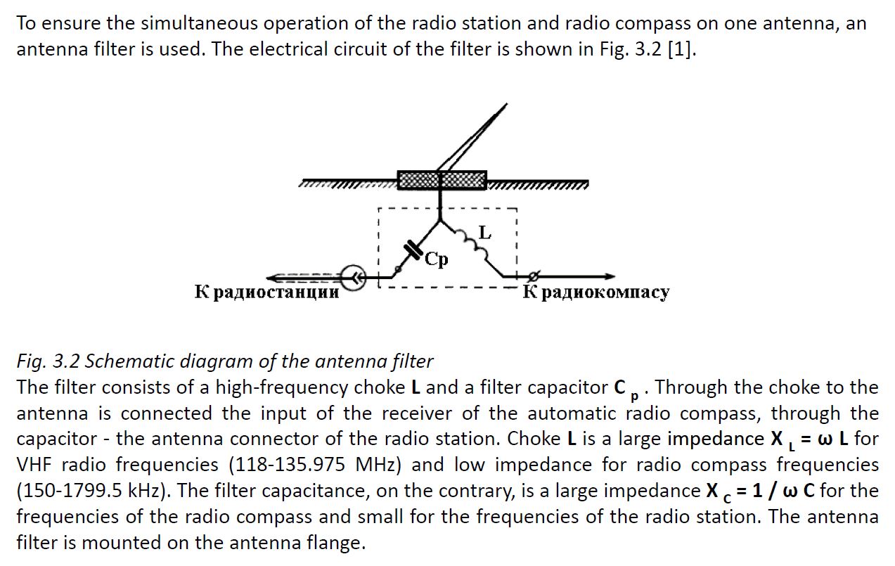
On that topic ... the original antenna has a crude 1st order RC high pass filter / splitter at the base of the antenna for the radio feed, and an LR low pass to the ADF sense feed, so the bulk of square wave ignition noise harmonic energy is filtered before it gets to the radio RF stage.
As radio is more your area of expertise than mine Mark I'd welcome your thoughts on finding a higher order in-line high pass filter suitable for a transceiver to work with replacement antennas.
Rob R.
Read this topic online here:
http://forums.matronics.com/viewtopic.php?p=481553#481553
| | - The Matronics Yak-List Email Forum - | | | Use the List Feature Navigator to browse the many List utilities available such as the Email Subscriptions page, Archive Search & Download, 7-Day Browse, Chat, FAQ, Photoshare, and much more:
http://www.matronics.com/Navigator?Yak-List |
|
|
|
| Back to top |
|
|
Rob Rowe
Joined: 10 Jan 2006
Posts: 124
Location: Berkshire, UK
|
| Posted: Fri Jul 13, 2018 4:57 am Post subject: Re: [Non-DoD Source] Re: Circuit breaker size for pitot hea |
|
|
Mark,


Thanks for your useful insight as always ... I don't have an original antenna to inspect, short of stripping the one out of my aircraft, and neither the analyser kit even if I did. So if you have an original antenna to hand and an analyser that would be very helpful to better understand empirically what is actually going on.


As you point out this was designed as a 'splitter' and not for the purpose of reducing RF interference into the original Baklan radios. But from practical experience (identical kit installs, by 40+ year avionics guy with same loom design and materials) it does appear to help some newer 8.33k replacement radios that are more sensitive to RFI.


I agree from Fourier principles the square wave RFI 'hash' will run across the band at odd harmonics that rapidly diminish in magnitude with increasing frequency, hence the high pass takes most of the lower frequency 'energy' out that probably helps the RF amp from being overwhelmed by transients. The original Baklan radios may not have needed this, but replacement radios seem to find it beneficial.


The attached schematic (extracted from a Russian doc) shows how simple the circuit is, that relies on the RF cable impedance to provide the 'R' component of the filters. Annoyingly no component values are given, nor on the original schematics, where it just refers to it as being factory manufactured, so custom made.


Given this is only a first order filter the roll-off slope is gentle, and to avoid attenuating the aircraft comms band, the Fc might be as low as 30Mhz. It will be interesting to see what your analyser results yield.


Hence finding a higher-order in-line diplexer alternative, as you've come up with, could be a big help and as I don't have the kit, or radio expertise, to provide definitive answers I really value your skills here.


Rob
| | - The Matronics Yak-List Email Forum - | | | Use the List Feature Navigator to browse the many List utilities available such as the Email Subscriptions page, Archive Search & Download, 7-Day Browse, Chat, FAQ, Photoshare, and much more:
http://www.matronics.com/Navigator?Yak-List |
|
| Description: |
|
| Filesize: |
157.44 KB |
| Viewed: |
2399 Time(s) |
|
|
|
| Back to top |
|
|
|
|
You cannot post new topics in this forum
You cannot reply to topics in this forum
You cannot edit your posts in this forum
You cannot delete your posts in this forum
You cannot vote in polls in this forum
You cannot attach files in this forum
You can download files in this forum
|
Powered by phpBB © 2001, 2005 phpBB Group
|

