 |
Matronics Email Lists
Web Forum Interface to the Matronics Email Lists
|
| View previous topic :: View next topic |
| Author |
Message |
kfav8r
Joined: 20 May 2012
Posts: 14
Location: Norman, OK
|
 Posted: Tue May 30, 2017 10:57 am Post subject: Re: IVO Prop current limiter Posted: Tue May 30, 2017 10:57 am Post subject: Re: IVO Prop current limiter |
 |
|
Will do Bob. Thanks!
| | - The Matronics AeroElectric-List Email Forum - | | | Use the List Feature Navigator to browse the many List utilities available such as the Email Subscriptions page, Archive Search & Download, 7-Day Browse, Chat, FAQ, Photoshare, and much more:
http://www.matronics.com/Navigator?AeroElectric-List |
|
_________________
Doug |
|
| Back to top |
|
 |
kfav8r
Joined: 20 May 2012
Posts: 14
Location: Norman, OK
|
| Posted: Wed Jun 07, 2017 12:41 pm Post subject: Re: IVO Prop current limiter |
|
|
Finally got the plane out to run the engine.  I modified the circuit, adding the 100 uF capacitor and the 10 Ohm resistor per Bob's instruction.


Same behavior as before -- without engine running, the blades would change pitch fairly consistently, with an occasional premature cut-off at the extremes when trying to reverse the pitch; with the engine running, the pitch would change slightly, but the power would be cut off rapidly.


I added my multi-meter in the loop to see what kind of current was flowing.  Without the engine running, cut-off would occur, as before, at around 9 Amps.


With the engine running, the meter indicated around 2 to 8 Amps before the circuit was shut down, with most readings around 2 to 5 or so Amps before cut-off.  Not sure how reliable the meter readings are given the quick circuit shut-down.
| | - The Matronics AeroElectric-List Email Forum - | | | Use the List Feature Navigator to browse the many List utilities available such as the Email Subscriptions page, Archive Search & Download, 7-Day Browse, Chat, FAQ, Photoshare, and much more:
http://www.matronics.com/Navigator?AeroElectric-List |
|
_________________
Doug |
|
| Back to top |
|
|
nuckolls.bob(at)aeroelect
Guest
|
| Posted: Thu Jun 08, 2017 5:30 pm Post subject: IVO Prop current limiter |
|
|
At 03:41 PM 6/7/2017, you wrote:
| Quote: | --> AeroElectric-List message posted by: "kfav8r" <kfav8r(at)outlook.com>
Finally got the plane out to run the engine. I modified the circuit, adding the 100 uF capacitor and the 10 Ohm resistor per Bob's instruction.
Same behavior as before -- without engine running, the blades would change pitch fairly consistently, with an occasional premature cut-off at the extremes when trying to reverse the pitch; with the engine running, the pitch would change slightly, but the power would be cut off rapidly.
I added my multi-meter in the loop to see what kind of current was flowing. Without the engine running, cut-off would occur, as before, at around 9 Amps.
With the engine running, the meter indicated around 2 to 8 Amps before the circuit was shut down, with most readings around 2 to 5 or so Amps before cut-off. Not sure how reliable the meter readings are given the quick circuit shut-down. |
Well . . . fooey. This isn't going to be a 'problem'
with your bus voltage. Circuits of this strip are
inherently sensitive to dv/dt (fast rise noise) effects.
Unfortunately, I didn't push this circuit through the
DO160 examination . . . hmmmm . . . I think I was still
at Raytheon/Beech. It's no doubt possible to tranquilize
the little critter with the right test equipment but
that's no longer in my bag of tricks.
Let's go to plan B. In the time since that circuit
was proposed, moving to a digital sensing, timing
and reaction circuit makes a lot of sense. There's
a LOT MORE separate between the bus and the parts
that sift the fine sands of performance.
I'm up to my eyeballs in a couple of programs now
but I'll see if I can sketch out the diagram and
get my super software guy to program a chip
to try.
Watch this space . . .
Bob . . .
| | - The Matronics AeroElectric-List Email Forum - | | | Use the List Feature Navigator to browse the many List utilities available such as the Email Subscriptions page, Archive Search & Download, 7-Day Browse, Chat, FAQ, Photoshare, and much more:
http://www.matronics.com/Navigator?AeroElectric-List |
|
|
|
| Back to top |
|
|
kfav8r
Joined: 20 May 2012
Posts: 14
Location: Norman, OK
|
| Posted: Tue Jun 27, 2017 10:37 am Post subject: Re: IVO Prop current limiter |
|
|
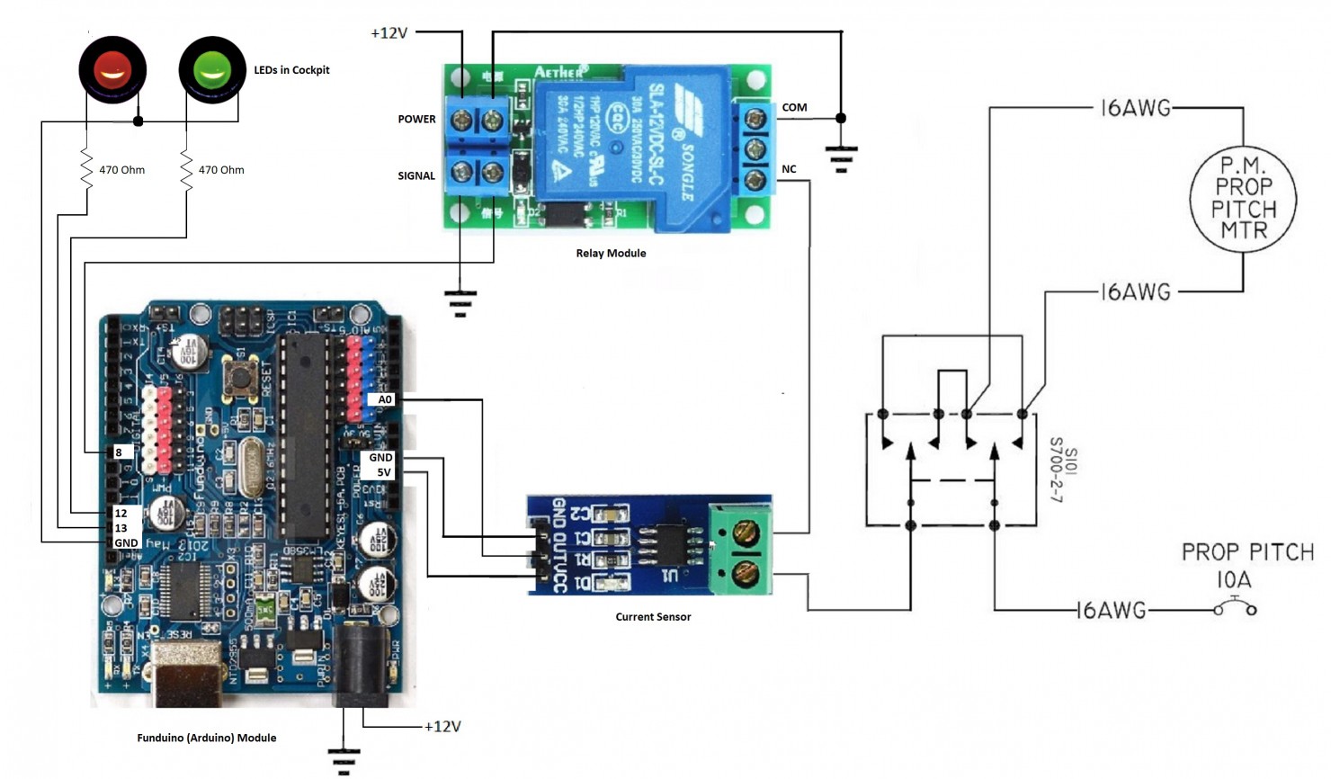
With Bob's prompting to move on to Plan B, I put together an Arduino-based IVOProp "controller."


I bought an Arduino clone, a relay module, and a current sensing module, and wrote a program to monitor the prop current.  When the current goes above 9 Amps for a sufficiently long time, the program opens the relay and shuts off the current.  The red and green LEDS are triggered to indicate the current flowing and not flowing to the prop.  The program leaves the relay open and the red LED on for a few seconds so the pilot gets the message that a limit was reached.


I just ran the engine and put the prop through its paces, and the system seems to work well.  There might be additional tweaking to the code needed, but I think it's pretty close to good.


I'll be happy to share the code and links to the components if anyone is interested.
| | - The Matronics AeroElectric-List Email Forum - | | | Use the List Feature Navigator to browse the many List utilities available such as the Email Subscriptions page, Archive Search & Download, 7-Day Browse, Chat, FAQ, Photoshare, and much more:
http://www.matronics.com/Navigator?AeroElectric-List |
|
_________________
Doug |
|
| Back to top |
|
|
nuckolls.bob(at)aeroelect
Guest
|
| Posted: Wed Jun 28, 2017 3:05 am Post subject: IVO Prop current limiter |
|
|
At 01:37 PM 6/27/2017, you wrote:
| Quote: | --> AeroElectric-List message posted by: "kfav8r" <kfav8r(at)outlook.com>
With Bob's prompting to move on to Plan B, I put together an Arduino-based IVOProp "controller."
I bought an Arduino clone, a relay module, and a current sensing module, and wrote a program to monitor the prop current. When the current goes above 9 Amps for a sufficiently long time, the program opens the relay and shuts off the current. The red and green LEDS are triggered to indicate the current flowing and not flowing to the prop. The program leaves the relay open and the red LED on for a few seconds so the pilot gets the message that a limit was reached.
I just ran the engine and put the prop through its paces, and the system seems to work well. There might be additional tweaking to the code needed, but I think it's pretty close to good. |
GOOD for YOU!
| Quote: | | I'll be happy to share the code and links to the components if anyone is interested. |
Yes, I'd be interested in seeing your work.
Bob . . .
| | - The Matronics AeroElectric-List Email Forum - | | | Use the List Feature Navigator to browse the many List utilities available such as the Email Subscriptions page, Archive Search & Download, 7-Day Browse, Chat, FAQ, Photoshare, and much more:
http://www.matronics.com/Navigator?AeroElectric-List |
|
|
|
| Back to top |
|
|
merlewagner2
Joined: 01 Jun 2016
Posts: 18
Location: Spring Hill, FL
|
| Posted: Wed Jun 28, 2017 3:58 am Post subject: Re: IVO Prop current limiter |
|
|
I would also like to take a look at your setup. I am planning on using an IVO mag prop with in flight adj. Was hoping to do just what you have already done. Way ahead of me!!!!
Merle
| Quote: | | I'll be happy to share the code and links to the components if anyone is interested. |
hmmm, seems I screwed up the quoting somehow..
| | - The Matronics AeroElectric-List Email Forum - | | | Use the List Feature Navigator to browse the many List utilities available such as the Email Subscriptions page, Archive Search & Download, 7-Day Browse, Chat, FAQ, Photoshare, and much more:
http://www.matronics.com/Navigator?AeroElectric-List |
|
_________________
KC1DNJ
General Radiotelephone
Commercial SEL
A & P
Building scale P51, rebuilding Tailwind W10 |
|
| Back to top |
|
|
kfav8r
Joined: 20 May 2012
Posts: 14
Location: Norman, OK
|
| Posted: Wed Jun 28, 2017 12:00 pm Post subject: Re: IVO Prop current limiter |
|
|
I'll get the info posted next week.
| | - The Matronics AeroElectric-List Email Forum - | | | Use the List Feature Navigator to browse the many List utilities available such as the Email Subscriptions page, Archive Search & Download, 7-Day Browse, Chat, FAQ, Photoshare, and much more:
http://www.matronics.com/Navigator?AeroElectric-List |
|
_________________
Doug |
|
| Back to top |
|
|
nuckolls.bob(at)aeroelect
Guest
|
| Posted: Wed Jun 28, 2017 12:24 pm Post subject: IVO Prop current limiter |
|
|
At 03:00 PM 6/28/2017, you wrote:
| Quote: | --> AeroElectric-List message posted by: "kfav8r" <kfav8r(at)outlook.com>
I'll get the info posted next week. |
This might be another opportunity for an open source
project. Once you've finely tuned the code, we can
poke it into chips for mounting on a dedicated
ecb . . . have you considered solid-state
switching as opposed to relay?
Bob . . .
| | - The Matronics AeroElectric-List Email Forum - | | | Use the List Feature Navigator to browse the many List utilities available such as the Email Subscriptions page, Archive Search & Download, 7-Day Browse, Chat, FAQ, Photoshare, and much more:
http://www.matronics.com/Navigator?AeroElectric-List |
|
|
|
| Back to top |
|
|
kfav8r
Joined: 20 May 2012
Posts: 14
Location: Norman, OK
|
| Posted: Thu Jul 06, 2017 8:04 am Post subject: Re: IVO Prop current limiter |
|
|
Attached is the Arduino code for, and a diagram of the IVOProp controller.

For the diagram, I used part of one of Bob's drawings, and added the Arduino components.


These are the components I used:

- Funduino ATMEGA328P Development Board

- ACS712 Current Sensor Module 20A

- SLA-12VDC-SL-C 12V 30A relay module


I had never worked with Arduino before, so I just bought what I thought made sense.

The Funduino board might be over-kill for this application; I'm sure there are plenty

of alternatives available. The Funduino board is apparently an Arduino-compatible clone.


All of the components were purchased on eBay.


For expedience, I put the current sensor between the prop adjuster switch and ground.

It would probably be better to have the sensor between the switch and the prop,

on one of the power lines. That would allow the code to see positive and negative readings,

depending on which direction the pitch is changing. You could then prevent further movement

of the prop in the same direction after a limit has been reached. Right now, the code cannot

determine in which direction the blades are moving.


The txt file is the Arduino code. Replace .txt with .ino to open it in the Arduino code editor.
| | - The Matronics AeroElectric-List Email Forum - | | | Use the List Feature Navigator to browse the many List utilities available such as the Email Subscriptions page, Archive Search & Download, 7-Day Browse, Chat, FAQ, Photoshare, and much more:
http://www.matronics.com/Navigator?AeroElectric-List |
|
| Description: |
|
| Filesize: |
184.54 KB |
| Viewed: |
15777 Time(s) |
|
| Description: |
|

Download |
| Filename: |
ivoprop_control.txt |
| Filesize: |
3.35 KB |
| Downloaded: |
473 Time(s) |
_________________
Doug |
|
| Back to top |
|
|
kfav8r
Joined: 20 May 2012
Posts: 14
Location: Norman, OK
|
| Posted: Thu Jul 06, 2017 8:16 am Post subject: Re: IVO Prop current limiter |
|
|
| Quote: | This might be another opportunity for an open source
project. Once you've finely tuned the code, we can
poke it into chips for mounting on a dedicated
ecb . . . have you considered solid-state
switching as opposed to relay? |
Bob,
I'm open to any of your great ideas.
I had not considered a solid-state switch instead of a relay,
but that does sound like a good way to go.
It would be nice to have this in a small package.
Right now, I have the Arduino (clone) board in an enclosure,
and the other components in the separate enclosure I had
been using for your original circuit.
Thanks,
| | - The Matronics AeroElectric-List Email Forum - | | | Use the List Feature Navigator to browse the many List utilities available such as the Email Subscriptions page, Archive Search & Download, 7-Day Browse, Chat, FAQ, Photoshare, and much more:
http://www.matronics.com/Navigator?AeroElectric-List |
|
_________________
Doug |
|
| Back to top |
|
|
yellowduckduo(at)gmail.co
Guest
|
| Posted: Thu Jul 06, 2017 9:05 am Post subject: IVO Prop current limiter |
|
|
For a smaller package, the 5 volt arduino clone pro mini boards are
under $2. delivered and can replace the funduino.
In my mind that makes them a no brainer to incorporate when building
multiple copies of something, instead of starting from scratch.
http://www.ebay.ca/itm/Pro-Mini-Enhancement-ATMEGA328P-5V-16MHz-Compatible-to-Arduino-PRO-mini-/191679508570?hash=item2ca0fd305a:g:AxIAAOSwT6pV5YIu
Boards like the funduino (uno clones) are much larger but include the 5
volt power supply regulator and USB interface and are usually more
convenient for one off projects or a first project.
Ken
On 06/07/2017 12:16 PM, kfav8r wrote:
| Quote: |
> This might be another opportunity for an open source
> project. Once you've finely tuned the code, we can
> poke it into chips for mounting on a dedicated
> ecb . . . have you considered solid-state
> switching as opposed to relay?
Bob,
I'm open to any of your great ideas.
I had not considered a solid-state switch instead of a relay,
but that does sound like a good way to go.
It would be nice to have this in a small package.
Right now, I have the Arduino (clone) board in an enclosure,
and the other components in the separate enclosure I had
been using for your original circuit.
Thanks,
--------
Doug
Read this topic online here:
http://forums.matronics.com/viewtopic.php?p=470728#470728
|
| | - The Matronics AeroElectric-List Email Forum - | | | Use the List Feature Navigator to browse the many List utilities available such as the Email Subscriptions page, Archive Search & Download, 7-Day Browse, Chat, FAQ, Photoshare, and much more:
http://www.matronics.com/Navigator?AeroElectric-List |
|
|
|
| Back to top |
|
|
nuckolls.bob(at)aeroelect
Guest
|
| Posted: Fri Jul 07, 2017 12:04 pm Post subject: IVO Prop current limiter |
|
|
At 11:16 AM 7/6/2017, you wrote:
| Quote: | --> AeroElectric-List message posted by: "kfav8r" <kfav8r(at)outlook.com>
> This might be another opportunity for an open source
> project. Once you've finely tuned the code, we can
> poke it into chips for mounting on a dedicated
> ecb . . . have you considered solid-state
> switching as opposed to relay?
Bob,
I'm open to any of your great ideas.
I had not considered a solid-state switch instead of a relay,
but that does sound like a good way to go.
It would be nice to have this in a small package.
Right now, I have the Arduino (clone) board in an enclosure,
and the other components in the separate enclosure I had
been using for your original circuit. |
Yup . . . make it work on the bench then
'distill' it . . .
Do I recall correctly that once you have
'golden code' in the silicon, the chip
can be lifted out and dropped into an
embedded controller with minimized
peripherals?
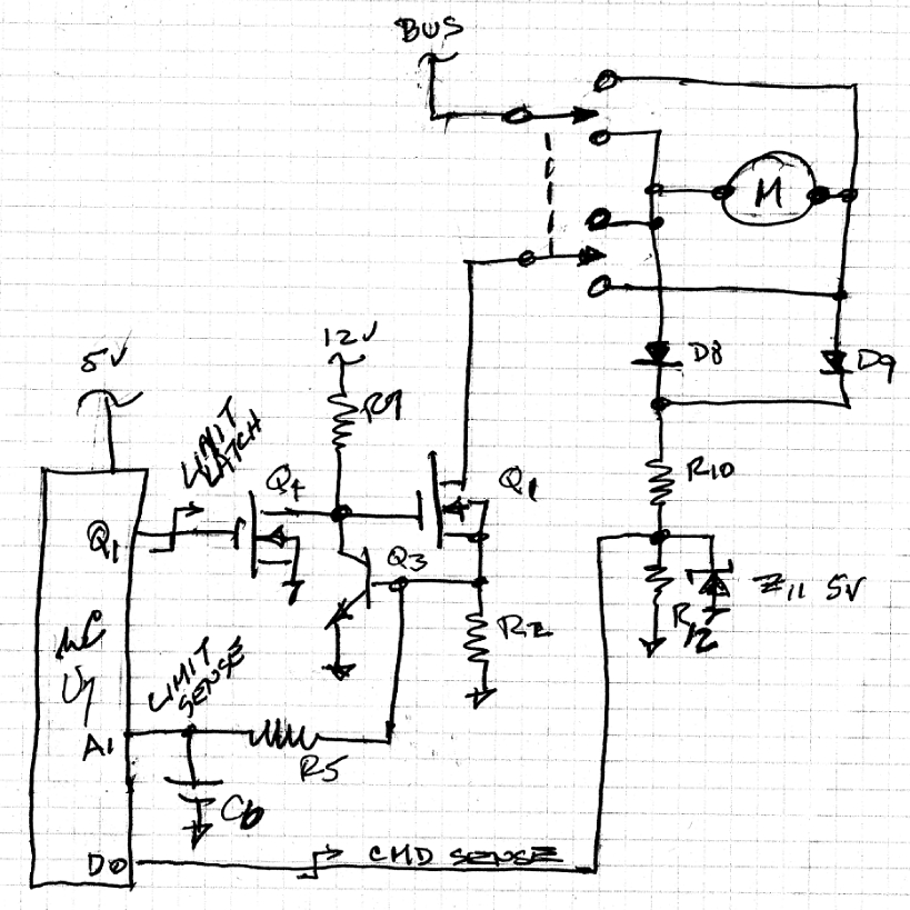
If I were stuffing this functionality into an
8-pin PIC chip, I would explore something
like this . . .
[img]cid:.0[/img]
Set up Q1/R2/Q3 as a classic, ultra-fast current
limiter. Select R2 to target stall motor current
limit. Current limit is approximately
I(limit) = Vbe(Q3)/R1
Vbe(Q3) is about 0.6 volts. Hence, setting
R1 at 0.1 ohms would get you a 6A current
limit. I think we were shooting for 9A so
R1 = 0.066 ohms. I would parallel a number
of resistors on an ECB to achieve 66 milliohms.
Q1 doubles as a motor controller turned OFF
by clamping gate to ground with Q4.
D8/D9/R10/C11/Z12 conditions the COMMAND SENSE
signal to a discrete input.
R5/C6 conditions a CURRENT LIMIT SENSE input
to an analog input.
Q4 is a software driven clamp to remove drive
from Q1 during a LIMIT CURRENT shut down.
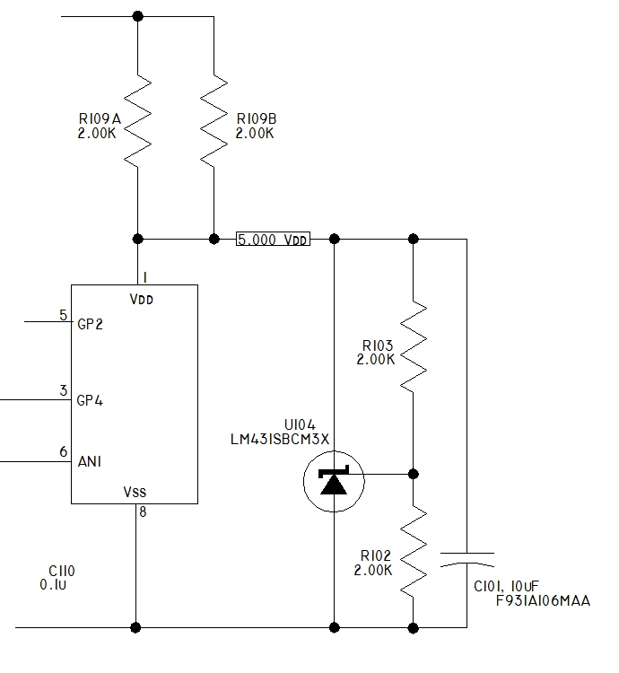
The +12 source in schematic above can be
BUS, a precision 5v source ie easily acquired for
small uC chips with a circuit like this:
[img]cid:.1[/img]
Smartware would read something like this:
Power-up routine SETS a LIMIT LATCH which
drives gate of Q4 HI.
A rising edge on COMMAND SENSE clears the
LIMIT LATCH which removes drive from gate of Q4.
LIMIT SENSE is monitored for input greater
than 0.5 volts for greater than 0.5 second.
Any excursion below 0.5 volts resets the
limit timer.
If limit times out, then the LIMIT LATCH
is SET, gate of Q4 goes HI and motor power
is removed.
This condition is sustained until next
rising edge on COMMAND SENSE.
It looks like the tiny Arduino products
could piggy-back onto a board that hosts
the peripheral components . . . but as
long as you're making a board, you might
explore the option of programming a chip
in an Arduino development system for
dropping into your target ECB.
To the extend that any of this is useful, feel
free to adopt or adapt as you see fit.
Bob . . .
| | - The Matronics AeroElectric-List Email Forum - | | | Use the List Feature Navigator to browse the many List utilities available such as the Email Subscriptions page, Archive Search & Download, 7-Day Browse, Chat, FAQ, Photoshare, and much more:
http://www.matronics.com/Navigator?AeroElectric-List |
|
| Description: |
|
| Filesize: |
380.67 KB |
| Viewed: |
15746 Time(s) |
|
| Description: |
|
| Filesize: |
83.07 KB |
| Viewed: |
15746 Time(s) |
|
|
|
| Back to top |
|
|
paulf(at)hughes.net
Guest
|
| Posted: Sat Jul 08, 2017 6:00 am Post subject: IVO Prop current limiter |
|
|
The software that Bob describes would be pretty simple to write for the PIC12F683 chip, the same chip we used for the wig-wag open source project. I'll volunteer to contribute the software if someone wants to pursue Bob's hardware design using a PIC chip instead of the Arduino as an open source project.
Paul Fisher
On 7/7/2017 3:03 PM, Robert L. Nuckolls, III wrote:
| Quote: | At 11:16 AM 7/6/2017, you wrote:
| Quote: | --> AeroElectric-List message posted by: "kfav8r" <kfav8r(at)outlook.com> (kfav8r(at)outlook.com)
> This might be another opportunity for an open source
> project. Once you've finely tuned the code, we can
> poke it into chips for mounting on a dedicated
> ecb . . . have you considered solid-state
> switching as opposed to relay?
Bob,
I'm open to any of your great ideas.
I had not considered a solid-state switch instead of a relay,
but that does sound like a good way to go.
It would be nice to have this in a small package.
Right now, I have the Arduino (clone) board in an enclosure,
and the other components in the separate enclosure I had
been using for your original circuit. |
Yup . . . make it work on the bench then
'distill' it . . .
Do I recall correctly that once you have
'golden code' in the silicon, the chip
can be lifted out and dropped into an
embedded controller with minimized
peripherals?
If I were stuffing this functionality into an
8-pin PIC chip, I would explore something
like this . . .
[img]cid:part1.F6F6D007.EBFDB47D(at)hughes.net[/img]
Set up Q1/R2/Q3 as a classic, ultra-fast current
limiter. Select R2 to target stall motor current
limit. Current limit is approximately
I(limit) = Vbe(Q3)/R1
Vbe(Q3) is about 0.6 volts. Hence, setting
R1 at 0.1 ohms would get you a 6A current
limit. I think we were shooting for 9A so
R1 = 0.066 ohms. I would parallel a number
of resistors on an ECB to achieve 66 milliohms.
Q1 doubles as a motor controller turned OFF
by clamping gate to ground with Q4.
D8/D9/R10/C11/Z12 conditions the COMMAND SENSE
signal to a discrete input.
R5/C6 conditions a CURRENT LIMIT SENSE input
to an analog input.
Q4 is a software driven clamp to remove drive
from Q1 during a LIMIT CURRENT shut down.
The +12 source in schematic above can be
BUS, a precision 5v source ie easily acquired for
small uC chips with a circuit like this:
[img]cid:part2.6F928517.BC423015(at)hughes.net[/img]
Smartware would read something like this:
Power-up routine SETS a LIMIT LATCH which
drives gate of Q4 HI.
A rising edge on COMMAND SENSE clears the
LIMIT LATCH which removes drive from gate of Q4.
LIMIT SENSE is monitored for input greater
than 0.5 volts for greater than 0.5 second.
Any excursion below 0.5 volts resets the
limit timer.
If limit times out, then the LIMIT LATCH
is SET, gate of Q4 goes HI and motor power
is removed.
This condition is sustained until next
rising edge on COMMAND SENSE.
It looks like the tiny Arduino products
could piggy-back onto a board that hosts
the peripheral components . . . but as
long as you're making a board, you might
explore the option of programming a chip
in an Arduino development system for
dropping into your target ECB.
To the extend that any of this is useful, feel
free to adopt or adapt as you see fit.
Bob . . . |
| | - The Matronics AeroElectric-List Email Forum - | | | Use the List Feature Navigator to browse the many List utilities available such as the Email Subscriptions page, Archive Search & Download, 7-Day Browse, Chat, FAQ, Photoshare, and much more:
http://www.matronics.com/Navigator?AeroElectric-List |
|
| Description: |
|
| Filesize: |
380.67 KB |
| Viewed: |
15731 Time(s) |

|
| Description: |
|
| Filesize: |
83.07 KB |
| Viewed: |
15731 Time(s) |

|
|
|
| Back to top |
|
|
alec(at)alecmyers.com
Guest
|
| Posted: Sat Jul 08, 2017 7:14 am Post subject: IVO Prop current limiter |
|
|
If you're going to use a pic you can dispense can
On Jul 8, 2017, at 9:59 AM, Paul A. T. 743 Fisher <paulf(at)hughes.net (paulf(at)hughes.net)> wrote:
| Quote: |
The software that Bob describes would be pretty simple to write for the PIC12F683 chip, the same chip we used for the wig-wag open source project. I'll volunteer to contribute the software if someone wants to pursue Bob's hardware design using a PIC chip instead of the Arduino as an open source project.
Paul Fisher
On 7/7/2017 3:03 PM, Robert L. Nuckolls, III wrote:
| Quote: | At 11:16 AM 7/6/2017, you wrote:
| Quote: | --> AeroElectric-List message posted by: "kfav8r" <kfav8r(at)outlook.com> (kfav8r(at)outlook.com)
> This might be another opportunity for an open source
> project. Once you've finely tuned the code, we can
> poke it into chips for mounting on a dedicated
> ecb . . . have you considered solid-state
> switching as opposed to relay?
Bob,
I'm open to any of your great ideas.
I had not considered a solid-state switch instead of a relay,
but that does sound like a good way to go.
It would be nice to have this in a small package.
Right now, I have the Arduino (clone) board in an enclosure,
and the other components in the separate enclosure I had
been using for your original circuit. |
Yup . . . make it work on the bench then
'distill' it . . .
Do I recall correctly that once you have
'golden code' in the silicon, the chip
can be lifted out and dropped into an
embedded controller with minimized
peripherals?
If I were stuffing this functionality into an
8-pin PIC chip, I would explore something
like this . . .
<5a5abb6.jpg>
Set up Q1/R2/Q3 as a classic, ultra-fast current
limiter. Select R2 to target stall motor current
limit. Current limit is approximately
I(limit) = Vbe(Q3)/R1
Vbe(Q3) is about 0.6 volts. Hence, setting
R1 at 0.1 ohms would get you a 6A current
limit. I think we were shooting for 9A so
R1 = 0.066 ohms. I would parallel a number
of resistors on an ECB to achieve 66 milliohms.
Q1 doubles as a motor controller turned OFF
by clamping gate to ground with Q4.
D8/D9/R10/C11/Z12 conditions the COMMAND SENSE
signal to a discrete input.
R5/C6 conditions a CURRENT LIMIT SENSE input
to an analog input.
Q4 is a software driven clamp to remove drive
from Q1 during a LIMIT CURRENT shut down.
The +12 source in schematic above can be
BUS, a precision 5v source ie easily acquired for
small uC chips with a circuit like this:
<5a5ac43.jpg>
Smartware would read something like this:
Power-up routine SETS a LIMIT LATCH which
drives gate of Q4 HI.
A rising edge on COMMAND SENSE clears the
LIMIT LATCH which removes drive from gate of Q4.
LIMIT SENSE is monitored for input greater
than 0.5 volts for greater than 0.5 second.
Any excursion below 0.5 volts resets the
limit timer.
If limit times out, then the LIMIT LATCH
is SET, gate of Q4 goes HI and motor power
is removed.
This condition is sustained until next
rising edge on COMMAND SENSE.
It looks like the tiny Arduino products
could piggy-back onto a board that hosts
the peripheral components . . . but as
long as you're making a board, you might
explore the option of programming a chip
in an Arduino development system for
dropping into your target ECB.
To the extend that any of this is useful, feel
free to adopt or adapt as you see fit.
Bob . . . |
|
| | - The Matronics AeroElectric-List Email Forum - | | | Use the List Feature Navigator to browse the many List utilities available such as the Email Subscriptions page, Archive Search & Download, 7-Day Browse, Chat, FAQ, Photoshare, and much more:
http://www.matronics.com/Navigator?AeroElectric-List |
|
|
|
| Back to top |
|
|
alec(at)alecmyers.com
Guest
|
| Posted: Sat Jul 08, 2017 9:45 am Post subject: IVO Prop current limiter |
|
|
Sorry - defective iPhones and all that.
Possible simplifications to consider:
- If youâre using a PIC maybe you could dispense with the current limiter. If you sense the current the PIC can send the FET high impedance within a few microseconds.
- dispense with the command sense input, and power the PIC with a simple potential divider from the command sense network instead. To reset the timer, remove the power shutting down the PIC and rebooting it when power is restored.
| Quote: | On Jul 8, 2017, at 11:12 AM, Alec Myers <alec(at)alecmyers.com (alec(at)alecmyers.com)> wrote:
If you're going to use a pic you can dispense can On Jul 8, 2017, at 9:59 AM, Paul A. T. 743 Fisher <paulf(at)hughes.net (paulf(at)hughes.net)> wrote:
| Quote: |
The software that Bob describes would be pretty simple to write for the PIC12F683 chip, the same chip we used for the wig-wag open source project. I'll volunteer to contribute the software if someone wants to pursue Bob's hardware design using a PIC chip instead of the Arduino as an open source project.
Paul Fisher On 7/7/2017 3:03 PM, Robert L. Nuckolls, III wrote:
| Quote: | At 11:16 AM 7/6/2017, you wrote: | Quote: | | --> AeroElectric-List message posted by: "kfav8r" <kfav8r(at)outlook.com> (kfav8r(at)outlook.com) > This might be another opportunity for an open source > project. Once you've finely tuned the code, we can > poke it into chips for mounting on a dedicated > ecb . . . have you considered solid-state > switching as opposed to relay? Bob, I'm open to any of your great ideas. I had not considered a solid-state switch instead of a relay, but that does sound like a good way to go. It would be nice to have this in a small package. Right now, I have the Arduino (clone) board in an enclosure, and the other components in the separate enclosure I had been using for your original circuit. |
Yup . . . make it work on the bench then 'distill' it . . . Do I recall correctly that once you have 'golden code' in the silicon, the chip can be lifted out and dropped into an embedded controller with minimized peripherals? If I were stuffing this functionality into an 8-pin PIC chip, I would explore something like this . . . <5a5abb6.jpg> Set up Q1/R2/Q3 as a classic, ultra-fast current limiter. Select R2 to target stall motor current limit. Current limit is approximately I(limit) = Vbe(Q3)/R1 Vbe(Q3) is about 0.6 volts. Hence, setting R1 at 0.1 ohms would get you a 6A current limit. I think we were shooting for 9A so R1 = 0.066 ohms. I would parallel a number of resistors on an ECB to achieve 66 milliohms. Q1 doubles as a motor controller turned OFF by clamping gate to ground with Q4. D8/D9/R10/C11/Z12 conditions the COMMAND SENSE signal to a discrete input. R5/C6 conditions a CURRENT LIMIT SENSE input to an analog input. Q4 is a software driven clamp to remove drive from Q1 during a LIMIT CURRENT shut down. The +12 source in schematic above can be BUS, a precision 5v source ie easily acquired for small uC chips with a circuit like this: <5a5ac43.jpg> Smartware would read something like this: Power-up routine SETS a LIMIT LATCH which drives gate of Q4 HI. A rising edge on COMMAND SENSE clears the LIMIT LATCH which removes drive from gate of Q4. LIMIT SENSE is monitored for input greater than 0.5 volts for greater than 0.5 second. Any excursion below 0.5 volts resets the limit timer. If limit times out, then the LIMIT LATCH is SET, gate of Q4 goes HI and motor power is removed. This condition is sustained until next rising edge on COMMAND SENSE. It looks like the tiny Arduino products could piggy-back onto a board that hosts the peripheral components . . . but as long as you're making a board, you might explore the option of programming a chip in an Arduino development system for dropping into your target ECB. To the extend that any of this is useful, feel free to adopt or adapt as you see fit.
Bob . . . |
|
|
| | - The Matronics AeroElectric-List Email Forum - | | | Use the List Feature Navigator to browse the many List utilities available such as the Email Subscriptions page, Archive Search & Download, 7-Day Browse, Chat, FAQ, Photoshare, and much more:
http://www.matronics.com/Navigator?AeroElectric-List |
|
|
|
| Back to top |
|
|
Eric Page
Joined: 15 Feb 2017
Posts: 243
|
| Posted: Sun Jul 09, 2017 12:05 am Post subject: IVO Prop current limiter |
|
|
I've converted Bob's sketches to a CAD file.  Anyone with interest in the project please look over my work (see attached PDF) and post any changes/critiques for the group to consider.  When we're all happy, I'll turn it into a printed circuit board, stuff it with parts and a DIP-8 socket, and send it to Paul so he can add a programmed PIC to test with his code.


A couple of notes:

- I've assumed that the DPDT motor-control relay will be mounted elsewhere (off the PCB).

- I've drawn a notional wiring diagram including a switch and a second relay.  If this isn't how the IVO prop works, let me know what to change.

- I guessed at the correct PIC GPIO pins to use.  Paul, let me know if you need something different.


Things to consider:

- For BOM simplicity, I used the same 2k resistors for R1-R8, and 0.1uF for C2 and C3.  Any problems with this?

- Any other component substitutions or value changes?

- What's the desired physical envelope (PCB with mounting holes / PCB for a small potting box / something else...)?

- What type of connector(s) should be used (a DB-9 is shown)?

- Are the fuse values on the wiring diagram appropriate?

- What AWG should be specified for each wire run?

Doug (kfav8r), in order to give you credit on the schematic, would you like to send me your last name?


Cheers,

Eric
| | - The Matronics AeroElectric-List Email Forum - | | | Use the List Feature Navigator to browse the many List utilities available such as the Email Subscriptions page, Archive Search & Download, 7-Day Browse, Chat, FAQ, Photoshare, and much more:
http://www.matronics.com/Navigator?AeroElectric-List |
|
| Description: |
|
Download |
| Filename: |
IVO_Prop_Current_Limiter.pdf |
| Filesize: |
121.74 KB |
| Downloaded: |
604 Time(s) |
|
|
| Back to top |
|
|
kfav8r
Joined: 20 May 2012
Posts: 14
Location: Norman, OK
|
| Posted: Sun Jul 09, 2017 6:01 am Post subject: Re: IVO Prop current limiter |
|
|
The DPDT switch is mounted in the panel (in my case), along with the red and green LEDs.

For the Arduino setup, I have the relay and the current sensing module in a box behind the panel, and the arduino placed nearby.

On my Arduino layout drawing, the right side is from one of Bob's original drawings. He included the 10 Amp circuit breaker there, since that is what is delivered with the IVOProp.

For wiring, I used 16 AWG for any wires handling prop motor current; that is the size delivered with the prop.

My name is Doug Garland, but true credit goes to Dennis Glaeser for starting this discussion years ago, and, of course, Bob.
| | - The Matronics AeroElectric-List Email Forum - | | | Use the List Feature Navigator to browse the many List utilities available such as the Email Subscriptions page, Archive Search & Download, 7-Day Browse, Chat, FAQ, Photoshare, and much more:
http://www.matronics.com/Navigator?AeroElectric-List |
|
_________________
Doug |
|
| Back to top |
|
|
paulf(at)hughes.net
Guest
|
| Posted: Sun Jul 09, 2017 6:59 am Post subject: IVO Prop current limiter |
|
|
Nicely drawn Eric!Â
Your message asks a lot of questions that I'm not qualified to answer. However, I can answer the question about the PIC pins you chose - they should work fine. I'll write the code based on the brief description Bob gave in his note. I'm assuming that a LIMIT SENSE of greater than 0.5 volts for more than 0.5 seconds is the trigger we want. I'll put those values in EEPROM fields on the chip so they are relatively easy to change if we want.
At some point we'll need someone with an IVO prop to actually test this and give us real world feedback.
This is fun!
Paul
On 7/9/2017 3:05 AM, Eric Page wrote:
| Quote: | I've converted Bob's sketches to a CAD file. Â Anyone with interest in the project please look over my work (see attached PDF) and post any changes/critiques for the group to consider. Â When we're all happy, I'll turn it into a printed circuit board, stuff it with parts and a DIP-8 socket, and send it to Paul so he can add a programmed PIC to test with his code.
A couple of notes:
- I've assumed that the DPDT motor-control relay will be mounted elsewhere (off the PCB).
- I've drawn a notional wiring diagram including a switch and a second relay. Â If this isn't how the IVO prop works, let me know what to change.
- I guessed at the correct PIC GPIO pins to use. Â Paul, let me know if you need something different.
Things to consider:
- For BOM simplicity, I used the same 2k resistors for R1-R8, and 0.1uF for C2 and C3. Â Any problems with this?
- Any other component substitutions or value changes?
- What's the desired physical envelope (PCB with mounting holes / PCB for a small potting box / something else...)?
- What type of connector(s) should be used (a DB-9 is shown)?
- Are the fuse values on the wiring diagram appropriate?
- What AWG should be specified for each wire run?
Doug (kfav8r), in order to give you credit on the schematic, would you like to send me your last name?
Cheers,
Eric
|
| | - The Matronics AeroElectric-List Email Forum - | | | Use the List Feature Navigator to browse the many List utilities available such as the Email Subscriptions page, Archive Search & Download, 7-Day Browse, Chat, FAQ, Photoshare, and much more:
http://www.matronics.com/Navigator?AeroElectric-List |
|
|
|
| Back to top |
|
|
nuckolls.bob(at)aeroelect
Guest
|
| Posted: Sun Jul 09, 2017 8:07 am Post subject: IVO Prop current limiter |
|
|
At 08:59 AM 7/8/2017, you wrote:
| Quote: | | The software that Bob describes would be pretty simple to write for the PIC12F683 chip, the same chip we used for the wig-wag open source project. I'll volunteer to contribute the software if someone wants to pursue Bob's hardware design using a PIC chip instead of the Arduino as an open source project. |
I'm up to my eyeballs in a couple of development
efforts along with juggling domestic duties . . .
but if someone wants to brassboard this project,
I'll volunteer to package it into a readily
duplicated product.
I've posted a proposed schematic of the controller
at http://tinyurl.com/ybbtw6dp
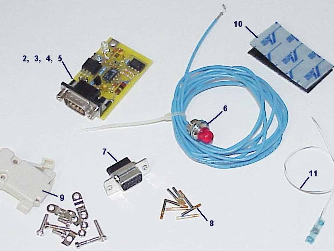
A minimalist approach to packaging would
look something like this. The fat power transistor
would be on the bottom, heat transfer surface down.
This would facilitate using airframe for heat-sinking
like our schottky e-bus diode did. The connector
would be 15 pin. The ECB footprint would be about
1.25 x 1.75 inches. The 'kit' would look something
like this except that the 700-2-7 switch is
missing.
[img]cid:.0[/img]
Oh yeah, had a gray-matter fart while crafting the
schematic. The software can get MUCH simpler.
On power up, the initialization CLEARS the LIMIT
LATCH and removes gate drive from the clamping
fet.
The analog input is monitored for amplitude greater
than 0.5 volts; greater than 0.5 seconds whereupon
the LIMIT LATCH is SET, gate of clamp fet goes
high and removed drive from the current limit fet.
An excursion below 0.5v will reset the LIMIT
TIMER.
After limit time out, the condition is sustained
until next power-down/power-up event.
I need to keep my head down on some more pressing
tasks for the next 10 days or so. You guys can
shepherd this along in the mean time.
Bob . . .
| | - The Matronics AeroElectric-List Email Forum - | | | Use the List Feature Navigator to browse the many List utilities available such as the Email Subscriptions page, Archive Search & Download, 7-Day Browse, Chat, FAQ, Photoshare, and much more:
http://www.matronics.com/Navigator?AeroElectric-List |
|
| Description: |
|
| Filesize: |
654.09 KB |
| Viewed: |
15715 Time(s) |
|
|
|
| Back to top |
|
|
nuckolls.bob(at)aeroelect
Guest
|
| Posted: Sun Jul 09, 2017 8:19 am Post subject: IVO Prop current limiter |
|
|
At 09:58 AM 7/9/2017, you wrote:
| Quote: | Nicely drawn Eric!Â
Your message asks a lot of questions that I'm not qualified to answer. However, I can answer the question about the PIC pins you chose - they should work fine. I'll write the code based on the brief description Bob gave in his note. I'm assuming that a LIMIT SENSE of greater than 0.5 volts for more than 0.5 seconds is the trigger we want. I'll put those values in EEPROM fields on the chip so they are relatively easy to change if we want.
At some point we'll need someone with an IVO prop to actually test this and give us real world feedback. |
Yes, brass-boarding is the acid test. You guys
had pushed this cart further down the road than
I thought since I sat down at the keyboard last
night.
Both .pdf and .dwg files of my work product are
at http://tinyurl.com/yby3waw6 for use
as the chefs of this design stew see fit.
I'll be standing by . . .
Bob . . .
| | - The Matronics AeroElectric-List Email Forum - | | | Use the List Feature Navigator to browse the many List utilities available such as the Email Subscriptions page, Archive Search & Download, 7-Day Browse, Chat, FAQ, Photoshare, and much more:
http://www.matronics.com/Navigator?AeroElectric-List |
|
|
|
| Back to top |
|
|
|
|
You cannot post new topics in this forum
You cannot reply to topics in this forum
You cannot edit your posts in this forum
You cannot delete your posts in this forum
You cannot vote in polls in this forum
You cannot attach files in this forum
You can download files in this forum
|
Powered by phpBB © 2001, 2005 phpBB Group
|

