 |
Matronics Email Lists
Web Forum Interface to the Matronics Email Lists
|
| View previous topic :: View next topic |
| Author |
Message |
Michael Wynn
Joined: 10 Jan 2006
Posts: 148
Location: San Ramon, CA
|
 Posted: Tue Aug 26, 2014 5:34 am Post subject: Shield wiring Posted: Tue Aug 26, 2014 5:34 am Post subject: Shield wiring |
 |
|
Hi all,


 I am upgrading my ELT to a 406 model.  The installation  instructions say to use a shielded wire to the GPS output.  My ELT is  located in the rear (RV8) and the GPS in the front.  Further, it requires  ground and power (about 240 mAh).


 I could easily run a 3 wire shielded cable from front to rear, ground at my  firewall forest of tabs and get power from a fuse block directly adjacent.   The question then becomes, how to get the shielded GPS signal from the panel to  the rear.  In terms of shortest wire run, bringing the GPS lead down from  the panel and joining the three wire from the rear at the gear tower would be  best.  If I use a shielded 20 gauge wire from the GPS down to join the  three wire from the rear, I need to figure out how to connect it to the GPS  designated wire in the three wire bundle.  Specifically, how to deal  with the shielding.  Should I ground it all at the firewall and somehow  solder the shields from the three wire and single wire together?  Should  the GPS lead be grounded both at the firewall and at the GPS ground  block?


 I could also run a single shielded wire from the GPS to the ELT, power the  ELT from my battery bus and ground the ELT to the fuselage locally.  That  would mean the ELT is constantly powered (as opposed to switched).  I draws  little power but could conceivably drain a battery over a long period of  time.


 Looking for help from the knowledgeable and experienced.


 Regards,


 Michael Wynn

 RV 8

 Livermore, CA

 [quote][b]
| | - The Matronics AeroElectric-List Email Forum - | | | Use the List Feature Navigator to browse the many List utilities available such as the Email Subscriptions page, Archive Search & Download, 7-Day Browse, Chat, FAQ, Photoshare, and much more:
http://www.matronics.com/Navigator?AeroElectric-List |
|
_________________
Michael Wynn
RV 8
San Ramon, CA |
|
| Back to top |
|
 |
nuckolls.bob(at)aeroelect
Guest
|
| Posted: Tue Aug 26, 2014 8:49 am Post subject: Shield wiring |
|
|
At 08:33 AM 8/26/2014, you wrote:
Hi all,
I am upgrading my ELT to a 406 model. The installation instructions say to use a shielded wire to the GPS output. My ELT is located in the rear (RV8) and the GPS in the front. Further, it requires ground and power (about 240 mAh).
I could easily run a 3 wire shielded cable from front to rear, ground at my firewall forest of tabs and get power from a fuse block directly adjacent. The question then becomes, how to get the shielded GPS signal from the panel to the rear. In terms of shortest wire run, bringing the GPS lead down from the panel and joining the three wire from the rear at the gear tower would be best.
What make/model is the ELT? Are there down-loadable
documents we can review?
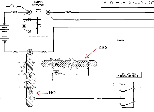
The ELT is not a candidate for grounding on the firewall forest of tabs (POWER STUFF). This is a piece of avionics. First, when the ELT is mounted in the airplane, is there any continuity between the power(-) wire that runs forward and ship's ground? I would hope not but it doesn't hurt to check. I would plan on grounding this article at the avionics ground on the panel.
[img]cid:7.1.0.9.0.20140826113749.04d509a8(at)aeroelectric.com.0[/img] [/b]
If I use a shielded 20 gauge wire from the GPS down to join the three wire from the rear, I need to figure out how to connect it to the GPS designated wire in the three wire bundle. Specifically, how to deal with the shielding. Should I ground it all at the firewall and somehow solder the shields from the three wire and single wire together? Should the GPS lead be grounded both at the firewall and at the GPS ground block?
I could also run a single shielded wire from the GPS to the ELT, power the ELT from my battery bus and ground the ELT to the fuselage locally. That would mean the ELT is constantly powered (as opposed to switched). I draws little power but could conceivably drain a battery over a long period of time.
Looking for help from the knowledgeable and experienced.
We REALLY need to see the installation documents before useful recommendations can be crafted.
Bob . . .
| | - The Matronics AeroElectric-List Email Forum - | | | Use the List Feature Navigator to browse the many List utilities available such as the Email Subscriptions page, Archive Search & Download, 7-Day Browse, Chat, FAQ, Photoshare, and much more:
http://www.matronics.com/Navigator?AeroElectric-List |
|
| Description: |
|
| Filesize: |
69.96 KB |
| Viewed: |
9635 Time(s) |

|
|
|
| Back to top |
|
|
Michael Wynn
Joined: 10 Jan 2006
Posts: 148
Location: San Ramon, CA
|
| Posted: Tue Aug 26, 2014 11:55 am Post subject: Shield wiring |
|
|
Hi Bob,
As usual, I appreciate your insights. Looks like this is a little more involved than I had originally thought.
My avionics ground is a thirty-seven pin Sub D that I think I got from your site. Five wires go from it to the forest of tabs on the firewall. All the avionics ground into this. The pins are all used so I may have to piggyback into a previously used pin.
The ELT is an ACK E-04. The installation manual is here:
http://www.ackavionics.com/pdf/E-04_REV_1.7_SINGLE_PAGE_REDUCED.pdf
I re-read the installation instructions and they really don't specify much about power or grounding. The only specification is "cockpit power" and "cockpit ground".
I would much appreciate your advice on proper installation.
Regards,
Michael Wynn
RV 8
Livermore
In a message dated 8/26/2014 10:59:49 A.M. Pacific Daylight Time, nuckolls.bob(at)aeroelectric.com writes:
| Quote: | At 08:33 AM 8/26/2014, you wrote:
Hi all,
I am upgrading my ELT to a 406 model. The installation instructions say to use a shielded wire to the GPS output. My ELT is located in the rear (RV8) and the GPS in the front. Further, it requires ground and power (about 240 mAh).
I could easily run a 3 wire shielded cable from front to rear, ground at my firewall forest of tabs and get power from a fuse block directly adjacent. The question then becomes, how to get the shielded GPS signal from the panel to the rear. In terms of shortest wire run, bringing the GPS lead down from the panel and joining the three wire from the rear at the gear tower would be best.
What make/model is the ELT? Are there down-loadable
documents we can review?
The ELT is not a candidate for grounding on the firewall forest of tabs (POWER STUFF). This is a piece of avionics. First, when the ELT is mounted in the airplane, is there any continuity between the power(-) wire that runs forward and ship's ground? I would hope not but it doesn't hurt to check. I would plan on grounding this article at the avionics ground on the panel.
[/b]
If I use a shielded 20 gauge wire from the GPS down to join the three wire from the rear, I need to figure out how to connect it to the GPS designated wire in the three wire bundle. Specifically, how to deal with the shielding. Should I ground it all at the firewall and somehow solder the shields from the three wire and single wire together? Should the GPS lead be grounded both at the firewall and at the GPS ground block?
I could also run a single shielded wire from the GPS to the ELT, power the ELT from my battery bus and ground the ELT to the fuselage locally. That would mean the ELT is constantly powered (as opposed to switched). I draws little power but could conceivably drain a battery over a long period of time.
Looking for help from the knowledgeable and experienced.
We REALLY need to see the installation documents before useful recommendations can be crafted.
Bob . . . |
| | - The Matronics AeroElectric-List Email Forum - | | | Use the List Feature Navigator to browse the many List utilities available such as the Email Subscriptions page, Archive Search & Download, 7-Day Browse, Chat, FAQ, Photoshare, and much more:
http://www.matronics.com/Navigator?AeroElectric-List |
|
| Description: |
|
| Filesize: |
69.96 KB |
| Viewed: |
9631 Time(s) |
|
_________________
Michael Wynn
RV 8
San Ramon, CA |
|
| Back to top |
|
|
nuckolls.bob(at)aeroelect
Guest
|
| Posted: Tue Aug 26, 2014 12:58 pm Post subject: Shield wiring |
|
|
At 02:48 PM 8/26/2014, you wrote:
| Quote: | Hi Bob,
As usual, I appreciate your insights. Looks like this is a little more involved than I had originally thought.
My avionics ground is a thirty-seven pin Sub D that I think I got from your site. Five wires go from it to the forest of tabs on the firewall. All the avionics ground into this. The pins are all used so I may have to piggyback into a previously used pin.
The ELT is an ACK E-04. The installation manual is here:
http://www.ackavionics.com/pdf/E-04_REV_1.7_SINGLE_PAGE_REDUCED.pdf |
Man! This is a pretty sorry manual considering all the
$time$ that somebody spent putting it together. There's
lots of data, probably accurate for the most part, but
horribly organized and formatted. On page 15 we find
this statement.
[img]cid:.0[/img]
The IMPORTANT item is 26 MICROAMPS standby current. This
means that lead is best fed from ship's battery bus. It
also says 1.4A average for 406 burst mode which has to be
bogus. It's got to be 1.4 amps for DURATION OF BURST with
something much lower between bursts. What's notably missing
is the ENERGY loading on this wire . . . which presumes that
the ELT's internal battery is depleted. Elsewhere we see
a "40 mA" tag on that wire . . . which may be the current
draw between bursts.
The RS232 "SEND TEST LINE" appears to be used only as
a LED driver to register acknowledgement of a GPS data
string on the "RECEIVE" line. I'd wire a resistor/LED into the
system permanently as opposed to the temporary jig
illustrated. This would function much as the REPLY
light on a transponder . . . a general tell-tale on the
systems operational state.
The power(-) lead should go to your avionics ground
Power(+) to the battery bus . . . use a 3A fuse.
RS232 RECEIVE connects to the RS232 SEND line
of your GPS receiver.
Bob . . .
| | - The Matronics AeroElectric-List Email Forum - | | | Use the List Feature Navigator to browse the many List utilities available such as the Email Subscriptions page, Archive Search & Download, 7-Day Browse, Chat, FAQ, Photoshare, and much more:
http://www.matronics.com/Navigator?AeroElectric-List |
|
| Description: |
|
| Filesize: |
45.59 KB |
| Viewed: |
9631 Time(s) |

|
|
|
| Back to top |
|
|
Michael Wynn
Joined: 10 Jan 2006
Posts: 148
Location: San Ramon, CA
|
| Posted: Tue Aug 26, 2014 1:27 pm Post subject: Shield wiring |
|
|
Thanks Bob,
You are the best.
Regards,
Michael Wynn
RV 8
Livermore, CA
In a message dated 8/26/2014 1:59:33 P.M. Pacific Daylight Time, nuckolls.bob(at)aeroelectric.com writes:
| Quote: | [img]res://C:\PROGRA~2\Nuance\NaturallySpeaking12\Program\web_ie.dll/QMARK.GIF[/img][img]res://C:\PROGRA~2\Nuance\NaturallySpeaking12\Program\web_ie.dll/ARROW.GIF[/img]At 02:48 PM 8/26/2014, you wrote:
| Quote: | Hi Bob,
As usual, I appreciate your insights. Looks like this is a little more involved than I had originally thought.
My avionics ground is a thirty-seven pin Sub D that I think I got from your site. Five wires go from it to the forest of tabs on the firewall. All the avionics ground into this. The pins are all used so I may have to piggyback into a previously used pin.
The ELT is an ACK E-04. The installation manual is here:
http://www.ackavionics.com/pdf/E-04_REV_1.7_SINGLE_PAGE_REDUCED.pdf |
Man! This is a pretty sorry manual considering all the
$time$ that somebody spent putting it together. There's
lots of data, probably accurate for the most part, but
horribly organized and formatted. On page 15 we find
this statement.
The IMPORTANT item is 26 MICROAMPS standby current. This
means that lead is best fed from ship's battery bus. It
also says 1.4A average for 406 burst mode which has to be
bogus. It's got to be 1.4 amps for DURATION OF BURST with
something much lower between bursts. What's notably missing
is the ENERGY loading on this wire . . . which presumes that
the ELT's internal battery is depleted. Elsewhere we see
a "40 mA" tag on that wire . . . which may be the current
draw between bursts.
The RS232 "SEND TEST LINE" appears to be used only as
a LED driver to register acknowledgement of a GPS data
string on the "RECEIVE" line. I'd wire a resistor/LED into the
system permanently as opposed to the temporary jig
illustrated. This would function much as the REPLY
light on a transponder . . . a general tell-tale on the
systems operational state.
The power(-) lead should go to your avionics ground
Power(+) to the battery bus . . . use a 3A fuse.
RS232 RECEIVE connects to the RS232 SEND line
of your GPS receiver.
Bob . . . |
| | - The Matronics AeroElectric-List Email Forum - | | | Use the List Feature Navigator to browse the many List utilities available such as the Email Subscriptions page, Archive Search & Download, 7-Day Browse, Chat, FAQ, Photoshare, and much more:
http://www.matronics.com/Navigator?AeroElectric-List |
|
| Description: |
|
| Filesize: |
45.59 KB |
| Viewed: |
9631 Time(s) |

|
_________________
Michael Wynn
RV 8
San Ramon, CA |
|
| Back to top |
|
|
kleh(at)dialupatcost.ca
Guest
|
| Posted: Tue Aug 26, 2014 2:41 pm Post subject: Shield wiring |
|
|
Quoted from below
"Power(+) to the battery bus . . . use a 3A fuse."
I don't think you want the power to this ELT wired to the battery bus.
The recommended 3 month test requires the power to the ELT to be off. We
used to get emails from SAR in Canada confirming satellite reception for
those 3 month tests but I'm always careful to make sure my master (power
to the ELT) is off when I test.
I picked this ELT specifically because it uses aircraft power to
pre-process gps position and have the position instantly available if
the unit is activated. It is news to me if aircraft power is also
available to supplement battery power for transmissions.
Ken
On 26/08/2014 4:57 PM, Robert L. Nuckolls, III wrote:
| Quote: | At 02:48 PM 8/26/2014, you wrote:
> Hi Bob,
>
> As usual, I appreciate your insights. Looks like this is a little
> more involved than I had originally thought.
>
> My avionics ground is a thirty-seven pin Sub D that I think I got from
> your site. Five wires go from it to the forest of tabs on the
> firewall. All the avionics ground into this. The pins are all used
> so I may have to piggyback into a previously used pin.
>
> The ELT is an ACK E-04. The installation manual is here:
> http://www.ackavionics.com/pdf/E-04_REV_1.7_SINGLE_PAGE_REDUCED.pdf
Man! This is a pretty sorry manual considering all the
$time$ that somebody spent putting it together. There's
lots of data, probably accurate for the most part, but
horribly organized and formatted. On page 15 we find
this statement.
Emacs!
The IMPORTANT item is 26 MICROAMPS standby current. This
means that lead is best fed from ship's battery bus. It
also says 1.4A average for 406 burst mode which has to be
bogus. It's got to be 1.4 amps for DURATION OF BURST with
something much lower between bursts. What's notably missing
is the ENERGY loading on this wire . . . which presumes that
the ELT's internal battery is depleted. Elsewhere we see
a "40 mA" tag on that wire . . . which may be the current
draw between bursts.
The RS232 "SEND TEST LINE" appears to be used only as
a LED driver to register acknowledgement of a GPS data
string on the "RECEIVE" line. I'd wire a resistor/LED into the
system permanently as opposed to the temporary jig
illustrated. This would function much as the REPLY
light on a transponder . . . a general tell-tale on the
systems operational state.
The power(-) lead should go to your avionics ground
Power(+) to the battery bus . . . use a 3A fuse.
RS232 RECEIVE connects to the RS232 SEND line
of your GPS receiver.
Bob . . .
|
| | - The Matronics AeroElectric-List Email Forum - | | | Use the List Feature Navigator to browse the many List utilities available such as the Email Subscriptions page, Archive Search & Download, 7-Day Browse, Chat, FAQ, Photoshare, and much more:
http://www.matronics.com/Navigator?AeroElectric-List |
|
|
|
| Back to top |
|
|
nuckolls.bob(at)aeroelect
Guest
|
| Posted: Wed Aug 27, 2014 7:30 am Post subject: Shield wiring |
|
|
At 05:40 PM 8/26/2014, you wrote:
| Quote: |
Quoted from below
"Power(+) to the battery bus . . . use a 3A fuse."
I don't think you want the power to this ELT wired to the battery
bus. The recommended 3 month test requires the power to the ELT to
be off. We used to get emails from SAR in Canada confirming
satellite reception for those 3 month tests but I'm always careful
to make sure my master (power to the ELT) is off when I test.
I picked this ELT specifically because it uses aircraft power to
pre-process gps position and have the position instantly available
if the unit is activated. It is news to me if aircraft power is also
available to supplement battery power for transmissions.
|
I'll ask ACK . . .
Bob . . .
| | - The Matronics AeroElectric-List Email Forum - | | | Use the List Feature Navigator to browse the many List utilities available such as the Email Subscriptions page, Archive Search & Download, 7-Day Browse, Chat, FAQ, Photoshare, and much more:
http://www.matronics.com/Navigator?AeroElectric-List |
|
|
|
| Back to top |
|
|
Michael Wynn
Joined: 10 Jan 2006
Posts: 148
Location: San Ramon, CA
|
| Posted: Tue Sep 02, 2014 5:40 am Post subject: Shield wiring |
|
|
Hi All,
Over the long weekend I got the ELT mounted, the remote mounted, the phone cable in. The really hard part was
In a message dated 8/27/2014 8:31:18 A.M. Pacific Daylight Time, nuckolls.bob(at)aeroelectric.com writes:
| Quote: | --> AeroElectric-List message posted by: "Robert L. Nuckolls, III" <nuckolls.bob(at)aeroelectric.com>
At 05:40 PM 8/26/2014, you wrote:
| Quote: | --> AeroElectric-List message posted by: Ken <kleh(at)dialupatcost.ca>
Quoted from below
"Power(+) to the battery bus . . . use a 3A fuse."
I don't think you want the power to this ELT wired to the battery
bus. The recommended 3 month test requires the power to the ELT to
be off. We used to get emails from SAR in Canada confirming
satellite reception for those 3 month tests but I'm always careful
to make sure my master (power to the ELT) is off when I test.
I picked this ELT specifically because it uses aircraft power to
pre-process gps position and have the position instantly available
if the unit is activated. It is news to me if aircraft power is also
available to supplement battery power for transmissions.
|
I'll ask ACK . . .
Bob . . . ========================= Use utilities Day ================================================ - MATRONICS WEB FORUMS ================================================ - List Contribution Web Site sp; ===================================================
|
[quote][b]
| | - The Matronics AeroElectric-List Email Forum - | | | Use the List Feature Navigator to browse the many List utilities available such as the Email Subscriptions page, Archive Search & Download, 7-Day Browse, Chat, FAQ, Photoshare, and much more:
http://www.matronics.com/Navigator?AeroElectric-List |
|
_________________
Michael Wynn
RV 8
San Ramon, CA |
|
| Back to top |
|
|
Michael Wynn
Joined: 10 Jan 2006
Posts: 148
Location: San Ramon, CA
|
| Posted: Tue Sep 02, 2014 5:53 am Post subject: Shield wiring |
|
|
Lets try that again. For unknown reasons, my computer occasionally sends mail prematurely.
Anyway, I got the ELT mounted, phone line in. The difficult part was fishing the three wire conductor from one end of the aircraft to the other. I have the ELT power, ground and GPS feed set up in this cable. It currently ends in the right gear tower. I have a fused power feed from a fuse block and a ground wire from my avionics ground bus.
Unfortunately, I miscalculated the length and am about two feet short on the three conductor getting to the back of the GPS. I have a single shielded wire which I planned to bring down from the GPS, terminating all together at the gear tower.
If I connect (solder) both shields and the ELT ground lead together and ground all of that to the avionics ground bus, will that do the trick? I did not ground the shield at the ELT end nor would I ground the shield at the GPS end.
The GPS is a Garmin GTN 650. Steinair, who wired my panel, has four feeds coming from a single feed (pin  . They suggested that I tap into this for the GPS feed. Two of the feeds go into Grand Rapids PFD and MFD. It would be a lot easier to tap into the circuit where they enter those units than into the GPS where there is already a four into one joint. I can't see that it makes any electrical different which end of the wire I join into. Am I missing anything here? . They suggested that I tap into this for the GPS feed. Two of the feeds go into Grand Rapids PFD and MFD. It would be a lot easier to tap into the circuit where they enter those units than into the GPS where there is already a four into one joint. I can't see that it makes any electrical different which end of the wire I join into. Am I missing anything here?
Thanks,
Michael Wynn
RV 8
Livermore, CA
In a message dated 8/27/2014 8:31:18 A.M. Pacific Daylight Time, nuckolls.bob(at)aeroelectric.com writes:
| Quote: | --> AeroElectric-List message posted by: "Robert L. Nuckolls, III" <nuckolls.bob(at)aeroelectric.com>
At 05:40 PM 8/26/2014, you wrote:
| Quote: | --> AeroElectric-List message posted by: Ken <kleh(at)dialupatcost.ca>
Quoted from below
"Power(+) to the battery bus . . . use a 3A fuse."
I don't think you want the power to this ELT wired to the battery
bus. The recommended 3 month test requires the power to the ELT to
be off. We used to get emails from SAR in Canada confirming
satellite reception for those 3 month tests but I'm always careful
to make sure my master (power to the ELT) is off when I test.
I picked this ELT specifically because it uses aircraft power to
pre-process gps position and have the position instantly available
if the unit is activated. It is news to me if aircraft power is also
available to supplement battery power for transmissions.
|
I'll ask ACK . . .
Bob . . . ========================= Use utilities Day ================================================ - MATRONICS WEB FORUMS ================================================ - List Contribution Web Site sp; ===================================================
|
[quote][b]
| | - The Matronics AeroElectric-List Email Forum - | | | Use the List Feature Navigator to browse the many List utilities available such as the Email Subscriptions page, Archive Search & Download, 7-Day Browse, Chat, FAQ, Photoshare, and much more:
http://www.matronics.com/Navigator?AeroElectric-List |
|
_________________
Michael Wynn
RV 8
San Ramon, CA |
|
| Back to top |
|
|
nuckolls.bob(at)aeroelect
Guest
|
| Posted: Thu Sep 04, 2014 7:44 am Post subject: Shield wiring |
|
|
At 08:52 AM 9/2/2014, you wrote:

Lets try that again.  For unknown reasons, my computer occasionally

sends mail prematurely.


   Mine too . . . but I think it's because my tongue

   is covering my eyeteeth and I can't see what I'm

   typing . ..

Anyway, I got the ELT mounted, phone line in.  The difficult part was

fishing the three wire conductor from one end of the aircraft to the

other.  I have the ELT power, ground and GPS feed set up in this

cable.  It currently ends in the right gear tower.  I have a fused

power feed from a fuse block and a ground wire from my avionics ground bus.

Unfortunately, I miscalculated the length and am about two feet short

on the three conductor getting to the back of the GPS.  I have a

single shielded wire which I planned to bring down from the GPS,

terminating all together at the gear tower.


If I connect (solder) both shields and the ELT ground lead together

and ground all of that to the avionics ground bus, will that do the

trick?  I did not ground the shield at the ELT end nor would I ground

the shield at the GPS end.


   Normally, a shielded wire carrying DATA is grounded

   at both ends . . . and the shield is part of the signal

   path. I am disappointed in ACK's installation instructions.

   For as long as they've been in the business I would have

   hoped the quality of their design and accompanying

   instructions would have matured.


   I'm adrift for crafting a rationale for doing any

   particular thing with the shields . . . it would

   be USEFUL to have some means by which signal

   integrity to the ELT could be verified. The manual

   speaks to tying an LED onto the ELT data transmit

   line to see if it 'flashes' in response to 1 second

   updates from the panel GPS. But the significance of

   that flash is not known. Does it NOT flash if there

   is some degradation of signal quality . . . checksum

   bad, framing bad????


   Given that so much FAITH is being placed on this

   piece of equipment to guide searchers to your remains,

   it would really be nice if their design included

   some means for demonstrating integrity as opposed

   to guessing.


   As I said . . . their instructions suck . . .


The GPS is a Garmin GTN 650.  Steinair, who wired my panel, has four

feeds coming from a single feed (pin .  They suggested that I tap

into this for the GPS feed.  Two of the feeds go into Grand Rapids

PFD and MFD.  It would be a lot easier to tap into the circuit where

they enter those units than into the GPS where there is already a

four into one joint.  I can't see that it makes any electrical

different which end of the wire I join into.  Am I missing anything here?


   Talk to Steinair about this. I'm not privy to the rationale

   for offering all these 'pigtails'. It's a mystery to me

   but they would be the one to explain their intentions.


   By the way, I did talk to ACK about the recommended power

   source for the E04. If you have a 'commericial' version

   (E04C) then power needs to come from a battery bus. If

   the plain vanilla version for little-guys, the power

   should come from a switched bus. Another little

   'gotcha' in their instructions.


   Sorry I can't be more help . . .


   Bob . . .
| | - The Matronics AeroElectric-List Email Forum - | | | Use the List Feature Navigator to browse the many List utilities available such as the Email Subscriptions page, Archive Search & Download, 7-Day Browse, Chat, FAQ, Photoshare, and much more:
http://www.matronics.com/Navigator?AeroElectric-List |
|
|
|
| Back to top |
|
|
Michael Wynn
Joined: 10 Jan 2006
Posts: 148
Location: San Ramon, CA
|
| Posted: Thu Sep 04, 2014 1:03 pm Post subject: Shield wiring |
|
|
I will wire it up as it looks simplest. I have the grounding and switched power set up. Once I connect the single, I will give it a test and report back.
Thanks,
Michael Wynn
In a message dated 9/4/2014 8:46:17 A.M. Pacific Daylight Time, nuckolls.bob(at)aeroelectric.com writes:
| Quote: | --> AeroElectric-List message posted by: "Robert L. Nuckolls, III" <nuckolls.bob(at)aeroelectric.com>
At 08:52 AM 9/2/2014, you wrote:
Lets try that again. For unknown reasons, my computer occasionally
sends mail prematurely.
Mine too . . . but I think it's because my tongue
is covering my eyeteeth and I can't see what I'm
typing . ..
Anyway, I got the ELT mounted, phone line in. The difficult part was
fishing the three wire conductor from one end of the aircraft to the
other. I have the ELT power, ground and GPS feed set up in this
cable. It currently ends in the right gear tower. I have a fused
power feed from a fuse block and a ground wire from my avionics ground bus.
Unfortunately, I miscalculated the length and am about two feet short
on the three conductor getting to the back of the GPS. I have a
single shielded wire which I planned to bring down from the GPS,
terminating all together at the gear tower.
If I connect (solder) both shields and the ELT ground lead together
and ground all of that to the avionics ground bus, will that do the
trick? I did not ground the shield at the ELT end nor would I ground
the shield at the GPS end.
Normally, a shielded wire carrying DATA is grounded
at both ends . . . and the shield is part of the signal
path. I am disappointed in ACK's installation instructions.
For as long as they've been in the business I would have
hoped the quality of their design and accompanying
instructions would have matured.
I'm adrift for crafting a rationale for doing any
particular thing with the shields . . . it would
be USEFUL to have some means by which signal
integrity to the ELT could be verified. The manual
speaks to tying an LED onto the ELT data transmit
line to see if it 'flashes' in response to 1 second
updates from the panel GPS. But the significance of
that flash is not known. Does it NOT flash if there
is some degradation of signal quality . . . checksum
bad, framing bad????
Given that so much FAITH is being placed on this
piece of equipment to guide searchers to your remains,
it would really be nice if their design included
some means for demonstrating integrity as opposed
to guessing.
As I said . . . their instructions suck . . .
The GPS is a Garmin GTN 650. Steinair, who wired my panel, has four
feeds coming from a single feed (pin . They suggested that I tap
into this for the GPS feed. Two of the feeds go into Grand Rapids
PFD and MFD. It would be a lot easier to tap into the circuit where
they enter those units than into the GPS where there is already a
four into one joint. I can't see that it makes any electrical
different which end of the wire I join into. Am I missing anything here?
Talk to Steinair about this. I'm not privy to the rationale
for offering all these 'pigtails'. It's a mystery to me
but they would be the one to explain their intentions.
By the way, I did talk to ACK about the recommended power
source for the E04. If you have a 'commericial' version
(E04C) then power needs to come from a battery bus. If
the plain vanilla version for little-guys, the power
should come from a switched bus. Another little
'gotcha' in their instructions.
Sorry I can't be more help . . .
Bob . . . ========================= Use utilities Day ================================================ - MATRONICS WEB FORUMS ================================================ - List Contribution Web Site sp; ===================================================
|
[quote][b]
| | - The Matronics AeroElectric-List Email Forum - | | | Use the List Feature Navigator to browse the many List utilities available such as the Email Subscriptions page, Archive Search & Download, 7-Day Browse, Chat, FAQ, Photoshare, and much more:
http://www.matronics.com/Navigator?AeroElectric-List |
|
_________________
Michael Wynn
RV 8
San Ramon, CA |
|
| Back to top |
|
|
nuckolls.bob(at)aeroelect
Guest
|
| Posted: Thu Sep 04, 2014 3:02 pm Post subject: Shield wiring |
|
|
At 04:01 PM 9/4/2014, you wrote:
| Quote: | I will wire it up as it looks simplest. I have the grounding and switched power set up. Once I connect the single, I will give it a test and report back.
Thanks,
Michael Wynn |
The 64-dollar question is how do you test it?
Without a receiver fitted with a feature that
resolves and displays the GPS location data being
transmitted by the ELT, how do you know that
the communications channel GPS->ELT is good?
I suppose avionics shops have that capability
these days. Does anyone on the List have
knowledge of this?
I wonder if Steinair hot-checks their pre-wired
panels.
Bob . . .
| Quote: |
In a message dated 9/4/2014 8:46:17 A.M. Pacific Daylight Time, nuckolls.bob(at)aeroelectric.com writes:
--> AeroElectric-List message posted by: "Robert L. Nuckolls, III" <nuckolls.bob(at)aeroelectric.com>
At 08:52 AM 9/2/2014, you wrote:
Lets try that again. For unknown reasons, my computer occasionally
sends mail prematurely.
Mine too . . . but I think it's because my tongue
is covering my eyeteeth and I can't see what I'm
typing . ..
Anyway, I got the ELT mounted, phone line in. The difficult part was
fishing the three wire conductor from one end of the aircraft to the
other. I have the ELT power, ground and GPS feed set up in this
cable. It currently ends in the right gear tower. I have a fused
power feed from a fuse block and a ground wire from my avionics ground bus.
Unfortunately, I miscalculated the length and am about two feet short
on the three conductor getting to the back of the GPS. I have a
single shielded wire which I planned to bring down from the GPS,
terminating all together at the gear tower.
If I connect (solder) both shields and the ELT ground lead together
and ground all of that to the avionics ground bus, will that do the
trick? I did not ground the shield at the ELT end nor would I ground
the shield at the GPS end.
Normally, a shielded wire carrying DATA is grounded
at both ends . . . and the shield is part of the signal
path. I am disappointed in ACK's installation instructions.
For as long as they've been in the business I would have
hoped the quality of their design and accompanying
instructions would have matured.
I'm adrift for crafting a rationale for doing any
particular thing with the shields . . . it would
be USEFUL to have some means by which signal
integrity to the ELT could be verified. The manual
speaks to tying an LED onto the ELT data transmit
line to see if it 'flashes' in response to 1 second
updates from the panel GPS. But the significance of
that flash is not known. Does it NOT flash if there
is some degradation of signal quality . . . checksum
bad, framing bad????
Given that so much FAITH is being placed on this
piece of equipment to guide searchers to your remains,
it would really be nice if their design included
some means for demonstrating integrity as opposed
to guessing.
As I said . . . their instructions suck . . .
The GPS is a Garmin GTN 650. Steinair, who wired my panel, has four
feeds coming from a single feed (pin . They suggested that I tap
into this for the GPS feed. Two of the feeds go into Grand Rapids
PFD and MFD. It would be a lot easier to tap into the circuit where
they enter those units than into the GPS where there is already a
four into one joint. I can't see that it makes any electrical
different which end of the wire I join into. Am I missing anything here?
Talk to Steinair about this. I'm not privy to the rationale
for offering all these 'pigtails'. It's a mystery to me
but they would be the one to explain their intentions.
By the way, I did talk to ACK about the recommended power
source for the E04. If you have a 'commericial' version
(E04C) then power needs to come from a battery bus. If
the plain vanilla version for little-guys, the power
should come from a switched bus. Another little
'gotcha' in their instructions.
Sorry I can't be more help . . |
Bob . . . [quote][b]
| | - The Matronics AeroElectric-List Email Forum - | | | Use the List Feature Navigator to browse the many List utilities available such as the Email Subscriptions page, Archive Search & Download, 7-Day Browse, Chat, FAQ, Photoshare, and much more:
http://www.matronics.com/Navigator?AeroElectric-List |
|
|
|
| Back to top |
|
|
jmjones2000(at)mindspring
Guest
|
| Posted: Thu Sep 04, 2014 3:50 pm Post subject: Shield wiring |
|
|
www.406Test.com
You pay a sign up fee and a beacon fee. The cost is $30 each.
You log into the website and schedule a test the of beacon. You have 48 hours to test it.
The beacon must be registered.
You must test it with a clear view of the southern sky.
You will receive an SMS text message confirming your test.
I'm unsure if it will give you a set of coordinates telling you where your beacon is or if it just says test successful. You may be able to find out on the website.
The specific question on weather or not the connectivity between your elt and GPS is working or not will probably need to be answered by an avionics shop with expensive test equipment. However you may get exact coordinates from the test website above. If you do, and they match within a few yards, it may be safe to assume the connection is working.
Side note: I had to put my garmin 430w into a programming mode to tell it what devices are connected to the rs232 and serial ports. There is a website telling you how to enter this programming mode. It was simple. Just hold down a button or combination of buttons during power application.
Hope this helps
Justin
On Sep 4, 2014, at 15:01, "Robert L. Nuckolls, III" <nuckolls.bob(at)aeroelectric.com (nuckolls.bob(at)aeroelectric.com)> wrote:
[quote] At 04:01 PM 9/4/2014, you wrote:
| Quote: | I will wire it up as it looks simplest. I have the grounding and switched power set up. Once I connect the single, I will give it a test and report back.
Thanks,
Michael Wynn |
The 64-dollar question is how do you test it?
Without a receiver fitted with a feature that
resolves and displays the GPS location data being
transmitted by the ELT, how do you know that
the communications channel GPS->ELT is good?
I suppose avionics shops have that capability
these days. Does anyone on the List have
knowledge of this?
I wonder if Steinair hot-checks their pre-wired
panels.
Bob . . .
| Quote: |
In a message dated 9/4/2014 8:46:17 A.M. Pacific Daylight Time, nuckolls.bob(at)aeroelectric.com (nuckolls.bob(at)aeroelectric.com) writes:
--> AeroElectric-List message posted by: "Robert L. Nuckolls, III" <nuckolls.bob(at)aeroelectric.com (nuckolls.bob(at)aeroelectric.com)>
At 08:52 AM 9/2/2014, you wrote:
Lets try that again. For unknown reasons, my computer occasionally
sends mail prematurely.
Mine too . . . but I think it's because my tongue
is covering my eyeteeth and I can't see what I'm
typing . ..
Anyway, I got the ELT mounted, phone line in. The difficult part was
fishing the three wire conductor from one end of the aircraft to the
other. I have the ELT power, ground and GPS feed set up in this
cable. It currently ends in the right gear tower. I have a fused
power feed from a fuse block and a ground wire from my avionics ground bus.
Unfortunately, I miscalculated the length and am about two feet short
on the three conductor getting to the back of the GPS. I have a
single shielded wire which I planned to bring down from the GPS,
terminating all together at the gear tower.
If I connect (solder) both shields and the ELT ground lead together
and ground all of that to the avionics ground bus, will that do the
trick? I did not ground the shield at the ELT end nor would I ground
the shield at the GPS end.
Normally, a shielded wire carrying DATA is grounded
at both ends . . . and the shield is part of the signal
path. I am disappointed in ACK's installation instructions.
For as long as they've been in the business I would have
hoped the quality of their design and accompanying
instructions would have matured.
I'm adrift for crafting a rationale for doing any
particular thing with the shields . . . it would
be USEFUL to have some means by which signal
integrity to the ELT could be verified. The manual
speaks to tying an LED onto the ELT data transmit
line to see if it 'flashes' in response to 1 second
updates from the panel GPS. But the significance of
that flash is not known. Does it NOT flash if there
is some degradation of signal quality . . . checksum
bad, framing bad????
Given that so much FAITH is being placed on this
piece of equipment to guide searchers to your remains,
it would really be nice if their design included
some means for demonstrating integrity as opposed
to guessing.
As I said . . . their instructions suck . . .
The GPS is a Garmin GTN 650. Steinair, who wired my panel, has four
feeds coming from a single feed (pin . They suggested that I tap
into this for the GPS feed. Two of the feeds go into Grand Rapids
PFD and MFD. It would be a lot easier to tap into the circuit where
they enter those units than into the GPS where there is already a
four into one joint. I can't see that it makes any electrical
different which end of the wire I join into. Am I missing anything here?
Talk to Steinair about this. I'm not privy to the rationale
for offering all these 'pigtails'. It's a mystery to me
but they would be the one to explain their intentions.
By the way, I did talk to ACK about the recommended power
source for the E04. If you have a 'commericial' version
(E04C) then power needs to come from a battery bus. If
the plain vanilla version for little-guys, the power
should come from a switched bus. Another little
'gotcha' in their instructions.
Sorry I can't be more help . . |
Bob . . . | Quote: |
===================================
st">http://www.matronics.com/Navigator?AeroElectric-List
===================================
cs.com
===================================
matronics.com/contribution
===================================
|
[b]
| | - The Matronics AeroElectric-List Email Forum - | | | Use the List Feature Navigator to browse the many List utilities available such as the Email Subscriptions page, Archive Search & Download, 7-Day Browse, Chat, FAQ, Photoshare, and much more:
http://www.matronics.com/Navigator?AeroElectric-List |
|
|
|
| Back to top |
|
|
glastar(at)gmx.net
Guest
|
| Posted: Fri Sep 05, 2014 12:03 am Post subject: Shield wiring |
|
|
What I did was putting my computer with a serial interface behind and
watched the data stream coming (on putty, it's NMEA 183) so I could see,
that the data was valid, if the ACK ELT can handle it correctly is
another question and I could not find out. Do not forget as well to have
the correct baud rate selected via the jumper inside!
Cheers
Werner
On 05.09.2014 01:01, Robert L. Nuckolls, III wrote:
| Quote: | The 64-dollar question is how do you test it?
Without a receiver fitted with a feature that
resolves and displays the GPS location data being
transmitted by the ELT, how do you know that
the communications channel GPS->ELT is good?
|
| | - The Matronics AeroElectric-List Email Forum - | | | Use the List Feature Navigator to browse the many List utilities available such as the Email Subscriptions page, Archive Search & Download, 7-Day Browse, Chat, FAQ, Photoshare, and much more:
http://www.matronics.com/Navigator?AeroElectric-List |
|
|
|
| Back to top |
|
|
nuckolls.bob(at)aeroelect
Guest
|
| Posted: Sat Sep 06, 2014 11:25 am Post subject: Shield wiring |
|
|
At 06:49 PM 9/4/2014, you wrote:
| Quote: | www.406Test.com
You pay a sign up fee and a beacon fee. The cost is $30 each.
You log into the website and schedule a test the of beacon. You have 48 hours to test it.
The beacon must be registered.
You must test it with a clear view of the southern sky.
You will receive an SMS text message confirming your test. |
Cool! Thanks for the heads-up. I've been unhooked from
the avionics side of the house for too long. The technology
is running over the horizon in front of me.
Bob . . . [quote][b]
| | - The Matronics AeroElectric-List Email Forum - | | | Use the List Feature Navigator to browse the many List utilities available such as the Email Subscriptions page, Archive Search & Download, 7-Day Browse, Chat, FAQ, Photoshare, and much more:
http://www.matronics.com/Navigator?AeroElectric-List |
|
|
|
| Back to top |
|
|
berkut13(at)berkut13.com
Guest
|
| Posted: Sun Sep 07, 2014 8:58 pm Post subject: Shield wiring |
|
|
..and know that the unit does not come with a jumper to use!  I robbed one

from an old computer hard drive for an ACK unit on another Berkut I'm

working on.

-James

Berkut/Race 13

--
| | - The Matronics AeroElectric-List Email Forum - | | | Use the List Feature Navigator to browse the many List utilities available such as the Email Subscriptions page, Archive Search & Download, 7-Day Browse, Chat, FAQ, Photoshare, and much more:
http://www.matronics.com/Navigator?AeroElectric-List |
|
|
|
| Back to top |
|
|
|
|
You cannot post new topics in this forum
You cannot reply to topics in this forum
You cannot edit your posts in this forum
You cannot delete your posts in this forum
You cannot vote in polls in this forum
You cannot attach files in this forum
You can download files in this forum
|
Powered by phpBB © 2001, 2005 phpBB Group
|

