 |
Matronics Email Lists
Web Forum Interface to the Matronics Email Lists
|
| View previous topic :: View next topic |
| Author |
Message |
rogsherriff(at)hotmail.co
Guest
|
 Posted: Fri Jan 06, 2017 2:50 pm Post subject: RV8 Elec schematic. Posted: Fri Jan 06, 2017 2:50 pm Post subject: RV8 Elec schematic. |
 |
|
Hello All,
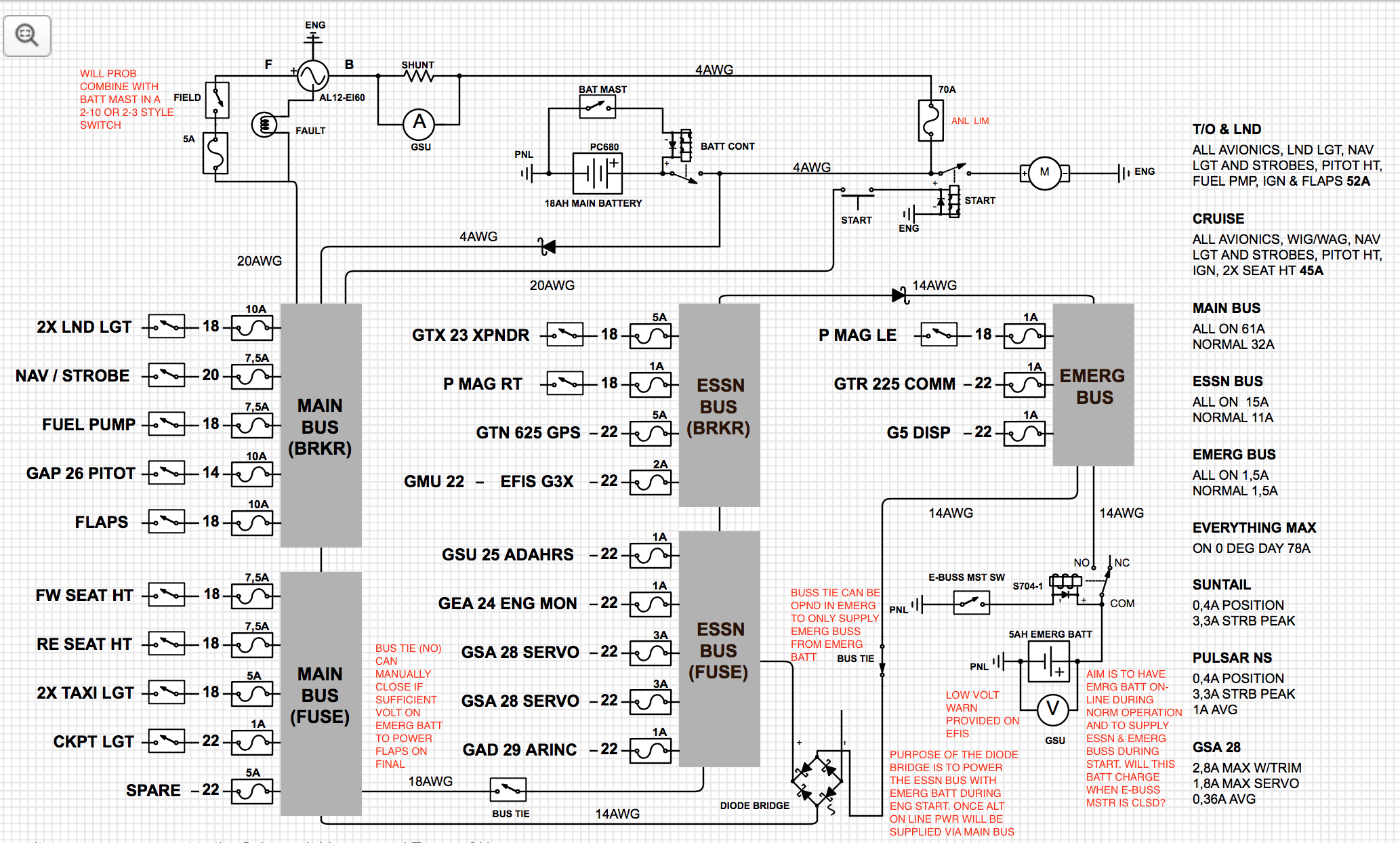
Sharpen your knives. I am the novice of novices and have strayed well out of my expertise and comfort zone and attempted to design an electrical system for my RV8. I have read the electrical bible (thank you Mr. Nuckolls) and used a combination of figure Z-10/8 and Z-11 as a guide. Attached schematics are a representation of my understanding.
I'd prefer not to have a hot battery bus or add a second alternator. Although IFR capable, it will be flown VFR or VMC most of the time. The system will run off a plane power 60A alt with built in OV and Voltage regulation. Engine is using 2 PMAG's and mechanical fuel injection. Main battery will probably go in the forward baggage compartment and the emergency battery location is yet tbd. Probably aft. Some consumers on the busses will use breakers and some will use fuses.
The philosophy is to power the essential and emergency busses using the emergency battery during start. Primarily to get the avionics setup without the engine running and then protecting against a voltage drop during start. After start it will remain online and all busses are powered by the alternator while charging both batt's. Max 75% ALT load in cruise.
Alternator fail- red light - (open emergency buss tie manually. I would like this to happen automatically but don't have the brainpower to design that yet, maybe later) will leave all busses powered by the main battery. All equipment on the main buss is switchable effectively leaving the essential buss powered by the main battery and emergency buss powered by the emergency battery. Following low volt on the main battery (2,5hrs health depending) the emergency battery powers emergency buss only. Max draw 1,5A so good for at least 3 hours (health depending) from start of alternator failure.
Could I please ask for your expert advice and commentary on my design? Don't be polite, there are lives on the line..
[img]cid:c88e7748-abd5-4055-b5ee-c64311dd7d38[/img]
Thank you in advance. Regards,
Roger.
p.s. I apologise if the schematic symbology details are not 100% correct. Still have to master the software.
| | - The Matronics AeroElectric-List Email Forum - | | | Use the List Feature Navigator to browse the many List utilities available such as the Email Subscriptions page, Archive Search & Download, 7-Day Browse, Chat, FAQ, Photoshare, and much more:
http://www.matronics.com/Navigator?AeroElectric-List |
|
| Description: |
|
| Filesize: |
638.56 KB |
| Viewed: |
3653 Time(s) |
|
|
|
| Back to top |
|
 |
user9253
Joined: 28 Mar 2008
Posts: 1972
Location: Riley TWP Michigan
|
| Posted: Fri Jan 06, 2017 8:33 pm Post subject: Re: RV8 Elec schematic. |
|
|
The wire between the battery contactor and the main bus does not have to be so big.
The diode in that wire will drop the voltage and it will get hot since it will carry the full aircraft electrical load.
Depending on where the voltage regulator senses voltage, field or "B" lead,
the battery could be charged at a higher voltage than intended.
The emergency battery might not charge because the charging voltage
will be dropped by the 3 diodes in series, the one in the main feeder,
the one in the bridge rectifier, and the one connected to the top of the emergency bus.
If the diode in main feeder is eliminated, and if the main bus tie is inadvertently closed,
the emergency battery will help crank the engine. That is not desired because heavy
current will flow in small wires and the emergency battery voltage will momentarily drop.
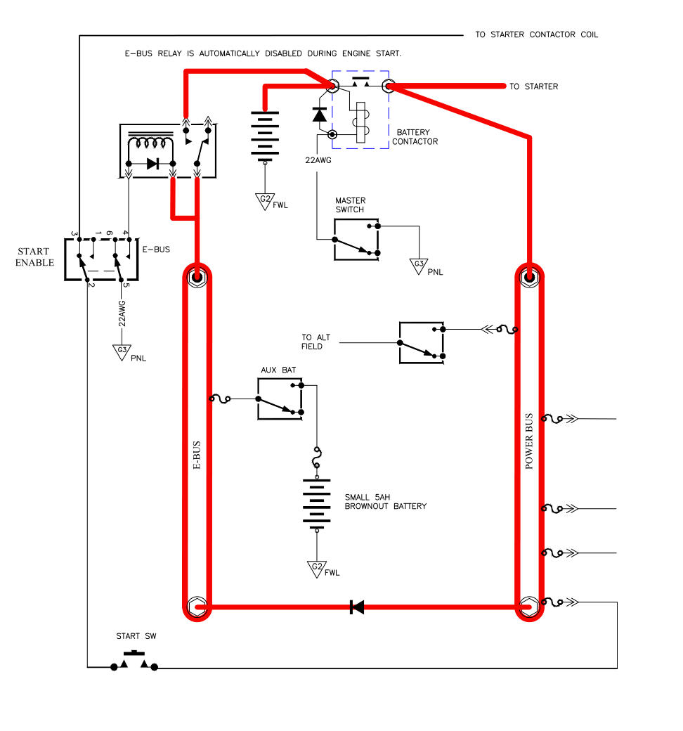
One of the purposes of the E-Bus switch in Bob N's circuits is to be able to shut off
the master contactor to conserve energy while still powering essential loads.
If your alternator fails, the master contactor must remain energized to utilize main battery stored energy.
It is hard to beat Bob's well proven designs.
Attached is a circuit to consider.
| | - The Matronics AeroElectric-List Email Forum - | | | Use the List Feature Navigator to browse the many List utilities available such as the Email Subscriptions page, Archive Search & Download, 7-Day Browse, Chat, FAQ, Photoshare, and much more:
http://www.matronics.com/Navigator?AeroElectric-List |
|
| Description: |
|
| Filesize: |
94.3 KB |
| Viewed: |
3641 Time(s) |
|
| Description: |
|

Download |
| Filename: |
Brownout Prevention 2.pdf |
| Filesize: |
22.96 KB |
| Downloaded: |
371 Time(s) |
_________________
Joe Gores |
|
| Back to top |
|
|
Peter(at)sportingaero.com
Guest
|
| Posted: Sun Jan 08, 2017 8:05 am Post subject: RV8 Elec schematic. |
|
|
Not many comments, haven’t spent very long looking, sorry if I haven’t understood how some stuff works.

4 AWG is a little large from Battery relay to main bus, could be smaller.

Could add circuit protection into starter button feed.

Size of fuses/breakers seems odd. Suggest standardise by wire size, for example,

22g = 5A, 20g = 7.5A, 18g = 10A, 16g = 15A

Do you really need 14g for the pitot?

Pmags need 5A fuses/breakers, I think.

GTR225 probably takes > 1A on transmit?

Do you need a relay on the emerg batt feed? A switch could handle the likely currents.

I would include an aux socket in the cockpit.

You do not show a trim motor?

A voltmeter on the main bus would be useful.

Why ground the starter relay to the engine? If it is mounted on the firewall just use that.


Load analysis is a little high – 78A continuous is too high for a 60A alternator, battery will be flat very quickly.

But too many loads are included. Do not include momentary loads, for example, flaps, radio transmit, trim.

Also relay loads not included (main relay often ~ 1A)? Spreadsheet for loads often easier.

Joe has raised a few issues I was going to mention.


Peter


From: owner-aeroelectric-list-server(at)matronics.com [mailto:owner-aeroelectric-list-server(at)matronics.com] On Behalf Of Roger Sherriff

Sent: 06 January 2017 22:46

To: aeroelectric-list(at)matronics.com

Subject: RV8 Elec schematic.


Hello All,


Sharpen your knives. I am the novice of novices and have strayed well out of my expertise and comfort zone and attempted to design an electrical system for my RV8. I have read the electrical bible (thank you Mr. Nuckolls) and used a combination of figure Z-10/8 and Z-11 as a guide. Attached schematics are a representation of my understanding.


I'd prefer not to have a hot battery bus or add a second alternator. Although IFR capable, it will be flown VFR or VMC most of the time. The system will run off a plane power 60A alt with built in OV and Voltage regulation. Engine is using 2 PMAG's and mechanical fuel injection. Main battery will probably go in the forward baggage compartment and the emergency battery location is yet tbd. Probably aft. Some consumers on the busses will use breakers and some will use fuses.


The philosophy is to power the essential and emergency busses using the emergency battery during start. Primarily to get the avionics setup without the engine running and then protecting against a voltage drop during start. After start it will remain online and all busses are powered by the alternator while charging both batt's. Max 75% ALT load in cruise.


Alternator fail- red light - (open emergency buss tie manually. I would like this to happen automatically but don't have the brainpower to design that yet, maybe later) will leave all busses powered by the main battery. All equipment on the main buss is switchable effectively leaving the essential buss powered by the main battery and emergency buss powered by the emergency battery. Following low volt on the main battery (2,5hrs health depending) the emergency  battery powers emergency buss only. Max draw 1,5A so good for at least 3 hours (health depending) from start of alternator failure.


Could I please ask for your expert advice and commentary on my design? Don't be polite, there are lives on the line..


[img]cid:image001.png(at)01D269C5.7F8DD100[/img]


Thank you in advance. Regards,


Roger.


p.s. I apologise if the schematic symbology details are not 100% correct. Still have to master the software.
| | - The Matronics AeroElectric-List Email Forum - | | | Use the List Feature Navigator to browse the many List utilities available such as the Email Subscriptions page, Archive Search & Download, 7-Day Browse, Chat, FAQ, Photoshare, and much more:
http://www.matronics.com/Navigator?AeroElectric-List |
|
| Description: |
|
| Filesize: |
638.56 KB |
| Viewed: |
3626 Time(s) |

|
|
|
| Back to top |
|
|
|
|
You cannot post new topics in this forum
You cannot reply to topics in this forum
You cannot edit your posts in this forum
You cannot delete your posts in this forum
You cannot vote in polls in this forum
You cannot attach files in this forum
You can download files in this forum
|
Powered by phpBB © 2001, 2005 phpBB Group
|

