 |
Matronics Email Lists
Web Forum Interface to the Matronics Email Lists
|
| View previous topic :: View next topic |
| Author |
Message |
nuckolls.bob(at)aeroelect
Guest
|
 Posted: Mon Aug 03, 2020 10:05 am Post subject: IS a COM ANTENNA GROUND PLANE NECESSARY Posted: Mon Aug 03, 2020 10:05 am Post subject: IS a COM ANTENNA GROUND PLANE NECESSARY |
 |
|
At 07:26 AM 8/3/2020, you wrote:
| Quote: | --> AeroElectric-List message posted by: "user9253" <fransew(at)gmail.com>
My friend abandoned the antenna embedded in the vertical stabilizer on his
Kitfox. He purchased a new antenna and mounted it atop the fuselage just aft
of the cargo area. The antenna base is mounted to a steel plate that is part
of the tubular steel airframe. |
Good
| Quote: | | The SWR was 1.95 when transmitting on 122.75. |
You need to run a spectrum plot. Check SWR
every 0.5 Mhz from 118 to 132 and plot
a curve.
| Quote: | | The ground plane could probably be improved if necessary. |
May not be necessary . . . you won't know
for sure until you get the 'big picture'
Generally speaking, an narrow-band antenna can have
a perfect or even low SWR at only one frequency.
That 'dip' in SWR may or may not be at the
antenna's resonant frequency.
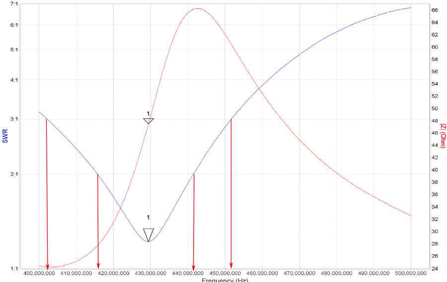
The attached plot illustrates an exemplar
antenna's performance over a range of frequencies.
The antenna's 'sweet spot' is at 429Mhz. The
antenna is satisfactory (2:1 or less) over a range
of about 416-442Mhz. Useful (3:1 or less) over
a range of 403-452Mhz.
Your SWR meter is a minimal utility vector network
analyzer. It just doesn't 'scan' or 'plot' for you
like a full featured VNA. However, with a little
data gathering and pencil work on a graph, you can
still get the information you need.
| Quote: | The wings were folded back during the SWR test. The aluminum flaperons were
within 6 inches of the antenna. Question: Do nearby metal objects
(flaperons) affect the SWR? If so, the the SWR test could be repeated when
the wings are unfolded. |
You want to do testing with the aircraft as
close to a flight condition as practical.
Yeah, conductors in close proximity do
have an effect.
Bob . . .
| | - The Matronics AeroElectric-List Email Forum - | | | Use the List Feature Navigator to browse the many List utilities available such as the Email Subscriptions page, Archive Search & Download, 7-Day Browse, Chat, FAQ, Photoshare, and much more:
http://www.matronics.com/Navigator?AeroElectric-List |
|
| Description: |
|
| Filesize: |
138.81 KB |
| Viewed: |
3132 Time(s) |

|
|
|
| Back to top |
|
 |
nuckolls.bob(at)aeroelect
Guest
|
| Posted: Mon Aug 03, 2020 10:07 am Post subject: IS a COM ANTENNA GROUND PLANE NECESSARY |
|
|
| Quote: | The wings were folded back during the SWR test. The aluminum flaperons were
within 6 inches of the antenna. Question: Do nearby metal objects
(flaperons) affect the SWR? If so, the the SWR test could be repeated when
the wings are unfolded. |
You want to do testing with the aircraft as
close to a flight condition as practical.
Yeah, conductors in close proximity do
have an effect.
Just for grins, you might run a scan with
the wings folded then repeat the exercise
with the aircraft in flight configuration.
I would be interesting to see how much
effect there is due to proximity of folded
wings.
Bob . . .
| | - The Matronics AeroElectric-List Email Forum - | | | Use the List Feature Navigator to browse the many List utilities available such as the Email Subscriptions page, Archive Search & Download, 7-Day Browse, Chat, FAQ, Photoshare, and much more:
http://www.matronics.com/Navigator?AeroElectric-List |
|
| Description: |
|
| Filesize: |
138.81 KB |
| Viewed: |
3132 Time(s) |
|
|
|
| Back to top |
|
|
nuckolls.bob(at)aeroelect
Guest
|
| Posted: Wed Aug 12, 2020 7:17 am Post subject: IS a COM ANTENNA GROUND PLANE NECESSARY |
|
|
| Quote: | | Surprise! The SWR greatly improved. |
Yup!
| Quote: | Below are the numbers. My friend might
experiment by adding additional ground plane radials. |
Probably won't change much . . .
| Quote: |
.
FREQ _ SWR
118 _ 2.30
119 _ 1.78
120 _ 1.49
121 _ 1.24
122 _ 1.20
123 _ 1.30
124 _ 1.35
125 _ 1.39
126 _ 1.59
127 _ 1.82
128 _ 1.95
129 _ 1.99
130 _ 2.00
131 _ 1.99
132 _ 2.00
133 _ 2.10
134 _ 2.20
135 _ 2.50
136 _ 3.10 |
The feedpoint impedance of an un-compensated
1/4 wave vertical is on the order of 30 ohms
at resonance . . . so the BEST expected SWR
over the range of interest would be about what
you're seeing 1.20:1
We see that SWR minimizes at 122, not quite in
the center of the range of interest. If this
antenna can be 'trimmed', try shortening it
1/4" at a time until SWR minimizes at 127Mhz.
Then I suspect you'll be under 3:1 over full
range . . . a useful antenna.
118 to 136 is a pretty BIG bandwidth . . .
about 14% . . . those numbers are not all
that bad! I'd go with it as-is or if
you're feeling ambitious, trim it a bit.
Good work!
Bob . . .
| | - The Matronics AeroElectric-List Email Forum - | | | Use the List Feature Navigator to browse the many List utilities available such as the Email Subscriptions page, Archive Search & Download, 7-Day Browse, Chat, FAQ, Photoshare, and much more:
http://www.matronics.com/Navigator?AeroElectric-List |
|
|
|
| Back to top |
|
|
user9253
Joined: 28 Mar 2008
Posts: 1908
Location: Riley TWP Michigan
|
| Posted: Wed Aug 12, 2020 8:45 am Post subject: Re: IS a COM ANTENNA GROUND PLANE NECESSARY |
|
|
Thanks for replying Bob.  The antenna is a beautiful Rami antenna.  I am sure

my friend does NOT want to cut it.  He might experiment with additional

ground plane wires, but otherwise leave it as is, not perfect but good enough.
| | - The Matronics AeroElectric-List Email Forum - | | | Use the List Feature Navigator to browse the many List utilities available such as the Email Subscriptions page, Archive Search & Download, 7-Day Browse, Chat, FAQ, Photoshare, and much more:
http://www.matronics.com/Navigator?AeroElectric-List |
|
_________________
Joe Gores |
|
| Back to top |
|
|
nuckolls.bob(at)aeroelect
Guest
|
| Posted: Wed Aug 12, 2020 9:08 am Post subject: IS a COM ANTENNA GROUND PLANE NECESSARY |
|
|
At 11:45 AM 8/12/2020, you wrote:
| Quote: | --> AeroElectric-List message posted by: "user9253" <fransew(at)gmail.com>
Thanks for replying Bob. The antenna is a beautiful Rami antenna. I am sure
my friend does NOT want to cut it. He might experiment with additional
ground plane wires, |
Useful experiment . . . pls share observations
| Quote: | | but otherwise leave it as is, not perfect but good enough. |
Right on . . .
Bob . . .
| | - The Matronics AeroElectric-List Email Forum - | | | Use the List Feature Navigator to browse the many List utilities available such as the Email Subscriptions page, Archive Search & Download, 7-Day Browse, Chat, FAQ, Photoshare, and much more:
http://www.matronics.com/Navigator?AeroElectric-List |
|
|
|
| Back to top |
|
|
nuckolls.bob(at)aeroelect
Guest
|
| Posted: Thu Aug 13, 2020 7:51 am Post subject: IS a COM ANTENNA GROUND PLANE NECESSARY |
|
|
At 09:21 AM 8/13/2020, you wrote:
| Quote: | --> AeroElectric-List message posted by: Finn Lassen <finn.usa(at)gmail.com>
Using the nanoVNA, I played with an old homemade comm antenna,
1/4 sticking up, three "ground plane" wires 120 degrees apart and bent downward.
It was amazing to me how the impedance and thus SWR changed with bending
the ground plane wires up or down a tiny bit. |
Yes!
| Quote: | | So, it's not just about adding ground plane wires, but also about how they slope down. |
Uhhh . . . yeah . . . mostly about the slope.
Imagine if you will, a 1/4 wave vertical with ONE
ground plane 'radial' except instead of radiating
out from the base, it is oriented straight down.
It's easy you see that you now have a 1/2 wave
dipole with an expected center point impedance
on the order of 70 ohms . . . not exactly a 1:1
but not terribly off either.
Going to the other extreme, consider the 1/4 wave
radiator in the middle of an solid, 1/4 wave radius
ground plane. Now you've got a feed point impedance on the order
of 35 ohms. Again, not 1:1 for 50 ohm coax but
not 'bad'.
Now, begin to deform the ground plane down from
the center in a cone shape. The feed point impedance
begins to rise. If taken to the limit of
deformation (90 degrees), you're now back
to a 1/2 wave dipole.
It follows that you can 'tune' swr by picking
a droop angle that optimizes your goal of
achieving a 50 ohm feed point.
A good example for designing this antenna
can be found here:
https://tinyurl.com/ybxfxuup
Try plugging in various values for center
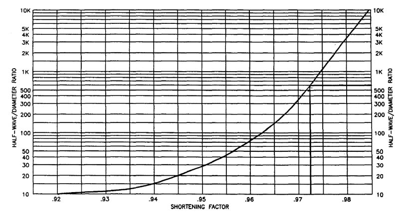
frequency and velocity factor. Did you know
that a radiator in free space has a velocity
factor? An antenna with zero diameter wire
has a velocity factor of 1.0
Obviously, zero diameter wire doesn't exist
so fine . . . we'll make it a stainless steel
rod of some structurally adequate size.
Figure 13-6 (attached) of the 'Connection speaks to
this phenomenon. The calculator linked above
takes this physics into account.
In practice, few folks concern themselves
with VF . . . they just trim for desired
results with an SWR/VNA meter.
Note also that the calculator adds a
'lengthening factor' of 0.28 to the
radials. This will have the effect of
making them slightly inductive at the
frequency of interest.
Bottom line is that with judicious tweaking
of the lengths and angles, one can handily
achieve a 1.0:1 match at the antenna feed
point.
Adding more radials up to and including
achievement of a solid conical plane will
have some effect but not nearly so profound
as observed with the first four radials plus some
judicious droop.
Unfortunately we don't have all
those options on airplanes . . . but in
the final analysis, pretty-good is good-enough.
Isn't that VNA a marvelous tool?
| Quote: | Of course, I don't know what impedance-matching network may be hiding in the RAMI antenna..
|
Some years ago, a reader sent me a schematic
of a 2-component, LC network that was thought
to be included in the base of a contemporary
VHF Comm antenna . . . I think it was a RAMI.
Couldn't put eyes on it at the moment.
Bob . . .
| | - The Matronics AeroElectric-List Email Forum - | | | Use the List Feature Navigator to browse the many List utilities available such as the Email Subscriptions page, Archive Search & Download, 7-Day Browse, Chat, FAQ, Photoshare, and much more:
http://www.matronics.com/Navigator?AeroElectric-List |
|
| Description: |
|
| Filesize: |
92.96 KB |
| Viewed: |
3020 Time(s) |
|
|
|
| Back to top |
|
|
|
|
You cannot post new topics in this forum
You cannot reply to topics in this forum
You cannot edit your posts in this forum
You cannot delete your posts in this forum
You cannot vote in polls in this forum
You cannot attach files in this forum
You can download files in this forum
|
Powered by phpBB © 2001, 2005 phpBB Group
|

