 |
Matronics Email Lists
Web Forum Interface to the Matronics Email Lists
|
| View previous topic :: View next topic |
| Author |
Message |
charlesdavis(at)iuncapped
Guest
|
 Posted: Sat Oct 31, 2020 10:44 pm Post subject: DIY LED landing light -- Wing skin as heat sink? Posted: Sat Oct 31, 2020 10:44 pm Post subject: DIY LED landing light -- Wing skin as heat sink? |
 |
|
How about ducting some of the slip-stream directly onto the heat-sink,
you could then use a MUCH smaller/lighter sink than relying on ambient
air inside the fitting
On 01/11/20 05:08 am, Finn Lassen wrote:
| Quote: |
Might say the most critical thing for LED life and high lumens output
is conducting heat away from the LED.
That usually means attaching heavy heat sinks.
Could we save weight by using the wing skin as a heat sink?
|
| | - The Matronics AeroElectric-List Email Forum - | | | Use the List Feature Navigator to browse the many List utilities available such as the Email Subscriptions page, Archive Search & Download, 7-Day Browse, Chat, FAQ, Photoshare, and much more:
http://www.matronics.com/Navigator?AeroElectric-List |
|
|
|
| Back to top |
|
 |
finn.usa(at)gmail.com
Guest
|
| Posted: Sun Nov 01, 2020 5:50 am Post subject: DIY LED landing light -- Wing skin as heat sink? |
|
|
That would introduce drag.
Name of the game here is no drag and lowest possible weight for max
light output (lumens) directed in a narrow beam that can reach 3,000
feet or more down a deer infested runway.
If it wasn't for needing the reflector to concentrate the light in a
beam, we could simply mount the LED chip flush with the wing skin, using
an alum backing plate (about the thickness of the one the LED chips
comes bonded to, I guess) and the wing skin would be a perfect heat sink.
My thermodynamic question comes into play as we move the LED chip
further back from the leading edge wing skin. Surely someone has
experience in designing heat sinks and what's required in terms of
conducting the heat from the point where a chip is mounted and out into
the fins exposed to air. Hopefully the thousands of heat sink design you
see are not all the result of trial and error. There must be some
physics (thermodynamics?) behind it.
Finn
On 11/1/2020 1:38 AM, Charles Davis wrote:
| Quote: |
<charlesdavis(at)iuncapped.co.za>
How about ducting some of the slip-stream directly onto the heat-sink,
you could then use a MUCH smaller/lighter sink than relying on ambient
air inside the fitting
On 01/11/20 05:08 am, Finn Lassen wrote:
>
> <finn.usa(at)gmail.com>
>
> Might say the most critical thing for LED life and high lumens output
> is conducting heat away from the LED.
>
> That usually means attaching heavy heat sinks.
>
> Could we save weight by using the wing skin as a heat sink?
|
---
This email has been checked for viruses by Avast antivirus software.
https://www.avast.com/antivirus
| | - The Matronics AeroElectric-List Email Forum - | | | Use the List Feature Navigator to browse the many List utilities available such as the Email Subscriptions page, Archive Search & Download, 7-Day Browse, Chat, FAQ, Photoshare, and much more:
http://www.matronics.com/Navigator?AeroElectric-List |
|
|
|
| Back to top |
|
|
finn.usa(at)gmail.com
Guest
|
| Posted: Sun Nov 01, 2020 6:26 am Post subject: DIY LED landing light -- Wing skin as heat sink? |
|
|
Thanks Todd. There are a multitude of LED solutions out there. I have a $20 4oz Trustfire 3T6 flashlight head that puts out 1,300 lumens (actually capable of 3,300 if I can get to and modify the internal driver in it and add proper cooling).
However , the 10 watt Cree XM-L2 or similar LED chips can now be had for $1.64 each. That's about 1,160 lumens if fed 10 watts. The newer XHP35, XHP72, etc. may or may not be slightly more efficient, but puts out light from a more dense location but are more expensive. The point here is that the LED solutions all come with (heavy) heat sinks. Even the drivers will need some cooling (think mounting the driver ICs/diodes on a wing rib).
70 to 80% of the power being fed to the LED chips needs to be dissipated as heat. That's right, LEDs are not more than 20 to 30% efficient!
All commercial and DIY LED landing light solutions I've seen so far come stand-alone. But why not design it into the aircraft? I guess not everyone is a weight freak like me.
Reason for using flashlight (torch) heads is they come with reflectors -- trick is to find ones with a narrow beam and low loss reflector and not having to pay for battery holder tube, heat sink, batteries etc. etc. But they all come with integrated drivers and heat sinks.
Some torches come with adjustable beam, but from what I've read they have rather lossy reflectors.
Now, a reflector like this https://www.stratusleds.com/module should probably do it, although I don't know the beam width. That's what started me thinking about using the LE wing skin as the heat sink. Needs a mount plate that can transfer the 70 or 80 watts of heat from the 34x34mm LED chip base to a sufficient area of wing skin. What's the heat "resistance" of 0.025 thick alum?
Finn
On 11/1/2020 2:58 AM, Todd Bartrim wrote:
| Quote: | Ooops, that was the link for my own collection of reference photos, This is the one you need to see how I did the lightsÂ
https://photos.app.goo.gl/wQvyosNK1QBFjz7c8 Todd Bartrim
On Sun, Nov 1, 2020 at 12:54 AM Todd Bartrim <bartrim(at)gmail.com (bartrim(at)gmail.com)> wrote:
| Quote: | Hi Finn; Â This may not be using the skin as a heat sink, but it works great and is lightweight.
I bought some of these lights from Amazon and took them apart to make my landing lights.
https://www.amazon.ca/Lightfox-Driving-Offroad-Waterproof-Warranty/dp/B01M98GWR2/ref=sr_1_2_sspa?crid=31MNRKKNOSJAA&dchild=1&keywords=led+spot+lights+offroad&qid=1604214923&sprefix=led+spot+%2Caps%2C274&sr=8-2-spons&psc=1&spLa=ZW5jcnlwdGVkUXVhbGlmaWVyPUEySTdLUVhZSDFQQTEmZW5jcnlwdGVkSWQ9QTA2NDM1NzcyUVdZV1QyR0tJS1dRJmVuY3J5cHRlZEFkSWQ9QTAwNzU1NTUzSzVRRTYzNTZSUjZHJndpZGdldE5hbWU9c3BfYXRmJmFjdGlvbj1jbGlja1JlZGlyZWN0JmRvTm90TG9nQ2xpY2s9dHJ1ZQ==
this is from Amazon's Canada site, but I'm sure you can find them even cheaper on the US site.
Then I took them apart as you can see in these pictures posted here on Google photos
https://photos.app.goo.gl/S68h3zpVy7RVJDTT8
I can't remember how much weight I discarded from the parts I removed, but it was most of the weight of the light.
The mounting plate was originally part of the Duckworths landing light that I wasted my money on. That is a simple part to make. I have 2 of those mounted mid wing and are pointed down for use as taxi lights, then I mounted 2 into the wingtips (required some fibreglass work) and have them pointed straight ahead for landing lights.
These lights are very durable and bright. I must have bought more than a dozen so far as I've put some on my truck, my son's Jeep, my skidsteer, 4 on the plane and probably the harshest duty is the pair I put on my ATV, which are thoroughly abused. They are extremely bright in the bush with very little current draw so my ATV has no problem running them continuously. I think those ones are at least 4 years old and are still working great despite the abuse.
 It looks like there are even better versions of these lights now, that appear to be the same construction so you can still dismantle them to get the good parts only.
Todd Bartrim
RV9
13BturboÂ
On Sat, Oct 31, 2020 at 8:20 PM Finn Lassen <finn.usa(at)gmail.com (finn.usa(at)gmail.com)> wrote:
| Quote: | --> AeroElectric-List message posted by: Finn Lassen <finn.usa(at)gmail.com (finn.usa(at)gmail.com)>
Might say the most critical thing for LED life and high lumens output is
conducting heat away from the LED.
That usually means attaching heavy heat sinks.
Could we save weight by using the wing skin as a heat sink?
I understand it would present problems in adjusting (pointing) the light.
But, could we bond/attach the LED to a (alum?) plate that is then
bonded/riveted/screwed to the leading edge wing skin?
Let's say we use a 100W LED (~13,000 lumens). We'd have to remove 70 to
80W of heat from the LED. LED doesn't like more than 150°C and it would
be better to keep it cooler. LED area 34x34mm.
I don't have a good grasp of thermal conductivity (conductance?). How
thick would the mount plate have to be? How much area would be needed
where the mount plate contacts the wing skin (using some kind of heat
sink compound/adhesive between the plate and skin)?
Am I right in assuming the plate has to be thickest were the LED is
mounted and then taper down in thickness as it expands out in width and
height?
Perhaps tapered layers of carbon fiber (with thermal epoxy) would be
better as the LED mount plate? (After a diamond, graphene or graphite
apparently has the best thermal conductivity.)
Any (thermal) engineers here that could enlighten me?
Finn
---
This email has been checked for viruses by Avast antivirus software.
https://www.avast.com/antivirus
===========
-
Electric-List" rel="noreferrer" target="_blank">http://www.matronics.com/Navigator?AeroElectric-List
===========
FORUMS -
eferrer" target="_blank">http://forums.matronics.com
===========
WIKI -
errer" target="_blank">http://wiki.matronics.com
===========
b Site -
     -Matt Dralle, List Admin.
rel="noreferrer" target="_blank">http://www.matronics.com/contribution
===========
|
|
|
 Virus-free. www.avast.com [url=#DAB4FAD8-2DD7-40BB-A1B8-4E2AA1F9FDF2] [/url] Virus-free. www.avast.com [url=#DAB4FAD8-2DD7-40BB-A1B8-4E2AA1F9FDF2] [/url]
| | - The Matronics AeroElectric-List Email Forum - | | | Use the List Feature Navigator to browse the many List utilities available such as the Email Subscriptions page, Archive Search & Download, 7-Day Browse, Chat, FAQ, Photoshare, and much more:
http://www.matronics.com/Navigator?AeroElectric-List |
|
|
|
| Back to top |
|
|
finn.usa(at)gmail.com
Guest
|
| Posted: Sun Nov 01, 2020 7:01 am Post subject: DIY LED landing light -- Wing skin as heat sink? |
|
|
Sorry, I was looking at the Cree XM-L2. 116 l/w. 116/350 = 33%. At least 5% loss in the driver. So about 31% or 69% heat dissipation. (Not sure about optical efficiency. I guess that's heat in the lens and reflector.)
So thickness of mount plate should not be a factor? A 10W LED I have has a 1.6mm thick metal base, but I guess that's needed to screw it down to heat sink with proper contact (minimal heat sink compound thickness).
Alum: 205 W/mK or 0.205W/C. But, but ... is cross area not a factor? Trying to compare it to electrical resistance in a wire. The higher the cross area -- the less resistance.
Trying to wrap my head around the transition from flat contact area under the LED chip to the heat sink plate as it expands out in area. Seems mounting it to an infinite piece of alum foil would not be the same as mounting it to 10x10" 0.063" thick alum plate ...
Finn
On 11/1/2020 9:25 AM, Robert L. Nuckolls, III wrote:
| Quote: | | Quote: | | Let's say we use a 100W LED (~13,000 lumens). We'd have to remove 70 to 80W of heat from the LED. |
AND the associated electronics.
See attached:
Bob . . . |
Virus-free. www.avast.com [url=#DAB4FAD8-2DD7-40BB-A1B8-4E2AA1F9FDF2] [/url]
| | - The Matronics AeroElectric-List Email Forum - | | | Use the List Feature Navigator to browse the many List utilities available such as the Email Subscriptions page, Archive Search & Download, 7-Day Browse, Chat, FAQ, Photoshare, and much more:
http://www.matronics.com/Navigator?AeroElectric-List |
|
|
|
| Back to top |
|
|
finn.usa(at)gmail.com
Guest
|
| Posted: Sun Nov 01, 2020 10:54 am Post subject: DIY LED landing light -- Wing skin as heat sink? |
|
|
On 11/1/2020 12:03 PM, Robert L. Nuckolls, III wrote:
| Quote: | | Quote: |
Trying to wrap my head around the transition from flat contact area under the LED chip to the heat sink plate as it expands out in area. Seems mounting it to an infinite piece of alum foil would not be the same as mounting it to 10x10" 0.063" thick alum plate ... |
But the sheet has thermal resistance too. And
rate of dissipation is a function of temperature
differential. As you move out onto the sheet,
the fastest transfer is right around the base
of the LED; temperatures fall as you move
out hence energy dissipated per unit area
declines.
Intuitively, it makes sense that 'sink'
temperature at the base of the LED will
be much higher than at a remote location.
Are we talking about landing lights?
Bob . . . |
Yes landing lights.
So my understanding is right. Thicker plate near LED base, then tapering out. You'll also see that in old big heat sinks: thick base then fins tapering out. I guess optimal design is total surface area versus enough material to conduct the heat to the entire surface (when designing for least weight). Some newer heat sinks I've seen have numerous rods sticking out from the base. Perhaps (for least weight) the rods should actually be tapered.
This my original question: "Am I right in assuming the plate has to be thickest were the LED is mounted and then taper down in thickness as it expands out in width and height?"
Another interesting item from Googling "best thermal conductivity":
"Along with its carbon cousins graphite and graphene, diamond is the best thermal conductor around room temperature, having thermal conductivity of more than 2,000 watts per meter per Kelvin, which is five times higher than the best metals such as copper."
leading to my: "Perhaps tapered layers of carbon fiber (with thermal epoxy) would be better as the LED mount plate? (After a diamond, graphene or graphite apparently has the best thermal conductivity.)"
One could shape the carbon fiber layup to closely fit the leading edge skin.
I guess I'm thinking way, way, way too far out of the box 
Finn
Virus-free. www.avast.com [url=#DAB4FAD8-2DD7-40BB-A1B8-4E2AA1F9FDF2] [/url]
| | - The Matronics AeroElectric-List Email Forum - | | | Use the List Feature Navigator to browse the many List utilities available such as the Email Subscriptions page, Archive Search & Download, 7-Day Browse, Chat, FAQ, Photoshare, and much more:
http://www.matronics.com/Navigator?AeroElectric-List |
|
|
|
| Back to top |
|
|
finn.usa(at)gmail.com
Guest
|
| Posted: Sun Nov 01, 2020 11:12 am Post subject: DIY LED landing light -- Wing skin as heat sink? |
|
|
Yes, that's where I got the position and strobe LEDs I'm working with at the moment, thanks to your posting here a long time ago.
Got 5 of the 10W super white LEDs. One for tail position/strobe. Two for each wingtip strobe.I also got the 10W green and red ones for wing position lights.
The tail LED will be driven with 300mA (via series diode) as a position light and then high-current pulses for strobing it.
I've read of over-driving LEDs for strobes. Max specs for the 10W LEDs says 1 amp, 1.5A peak. I would like to give them a 100ms (or less) 10A pulse. My big question is if that would violate the 1.5A peak spec.
Fiddling with a LM324 quad single-supply op-amp. Looking at application examples I found that it's actually possible to make just one op-amp generate 100ms pulses every 1 sec with 5 resistors, one capacitor and one diode. Also can run directly on ship's power. (max 32V). Now I'm looking for a P-channel MOSFET to drive the LED to max voltage. I guess I could use a PNP power transistor I've got laying around ...
Finn
On 11/1/2020 11:06 AM, Ernest Christley wrote:
| Quote: | I got might lights from https://www.mpja.com/20-30-50-Watt-LEDs/products/580/
The drivers are riveted to the wing skin and the LED riveted to a plate of .080" aluminum. They were then riveted to Zenith's mount plate (I have a 601XL). I didn't bother to use any reflectors, as the LEDs tend to concentrate light in one area. One 30W driver wiill handle three 10W LEDs. That will spread the heat out.Â
Cooling air is provided by a 1/8" hole drilled to stop a crack in the plexiglass cover  If anyone can measure the drag of that 1/8" hole, you're smart enough that I want to be your friend.
On Sunday, November 1, 2020, 10:02:03 AM EST, Finn Lassen <finn.usa(at)gmail.com> (finn.usa(at)gmail.com) wrote:
Sorry, I was looking at the Cree XM-L2. 116 l/w. 116/350 = 33%. At least 5% loss in the driver. So about 31% or 69% heat dissipation. (Not sure about optical efficiency. I guess that's heat in the lens and reflector.)
So thickness of mount plate should not be a factor? A 10W LED I have has a 1.6mm thick metal base, but I guess that's needed to screw it down to heat sink with proper contact (minimal heat sink compound thickness).
Alum: 205 W/mK or 0.205W/C. But, but ... is cross area not a factor? Trying to compare it to electrical resistance in a wire. The higher the cross area -- the less resistance.
Trying to wrap my head around the transition from flat contact area under the LED chip to the heat sink plate as it expands out in area. Seems mounting it to an infinite piece of alum foil would not be the same as mounting it to 10x10" 0.063" thick alum plate ...
Finn
On 11/1/2020 9:25 AM, Robert L. Nuckolls, III wrote:
| Quote: | | Quote: | | Let's say we use a 100W LED (~13,000 lumens). We'd have to remove 70 to 80W of heat from the LED. |
 AND the associated electronics.
Â
 See attached:
 Bob . . . |
Virus-free. www.avast.com [url=#DAB4FAD8-2DD7-40BB-A1B8-4E2AA1F9FDF2] [/url]
|
| | - The Matronics AeroElectric-List Email Forum - | | | Use the List Feature Navigator to browse the many List utilities available such as the Email Subscriptions page, Archive Search & Download, 7-Day Browse, Chat, FAQ, Photoshare, and much more:
http://www.matronics.com/Navigator?AeroElectric-List |
|
|
|
| Back to top |
|
|
echristley(at)att.net
Guest
|
| Posted: Sun Nov 01, 2020 1:24 pm Post subject: DIY LED landing light -- Wing skin as heat sink? |
|
|
Another option is to mount the LED in the center of a disk. Drill a ring of 1/8" holes right up next to the LED. Then a ring of 3/16" holes a little further out. Then a ring of 1/4", etc.The plate provides a way to mount to the wing.
On Sunday, November 1, 2020, 3:38:03 PM EST, Charlie England <ceengland7(at)gmail.com> wrote:
On Sun, Nov 1, 2020 at 12:59 PM Finn Lassen <finn.usa(at)gmail.com (finn.usa(at)gmail.com)> wrote:
| Quote: |
On 11/1/2020 12:03 PM, Robert L. Nuckolls, III wrote:
| Quote: | | Quote: |
Trying to wrap my head around the transition from flat contact area under the LED chip to the heat sink plate as it expands out in area. Seems mounting it to an infinite piece of alum foil would not be the same as mounting it to 10x10" 0.063" thick alum plate ... |
But the sheet has thermal resistance too. And
rate of dissipation is a function of temperature
differential. As you move out onto the sheet,
the fastest transfer is right around the base
of the LED; temperatures fall as you move
out hence energy dissipated per unit area
declines.
Intuitively, it makes sense that 'sink'
temperature at the base of the LED will
be much higher than at a remote location.
Are we talking about landing lights?
Bob . . . |
Yes landing lights.
So my understanding is right. Thicker plate near LED base, then tapering out. You'll also see that in old big heat sinks: thick base then fins tapering out. I guess optimal design is total surface area versus enough material to conduct the heat to the entire surface (when designing for least weight). Some newer heat sinks I've seen have numerous rods sticking out from the base. Perhaps (for least weight) the rods should actually be tapered.
This my original question: "Am I right in assuming the plate has to be thickest were the LED is mounted and then taper down in thickness as it expands out in width and height?"
Another interesting item from Googling "best thermal conductivity":
"Along with its carbon cousins graphite and graphene, diamond is the best thermal conductor around room temperature, having thermal conductivity of more than 2,000 watts per meter per Kelvin, which is five times higher than the best metals such as copper."
leading to my: "Perhaps tapered layers of carbon fiber (with thermal epoxy) would be better as the LED mount plate? (After a diamond, graphene or graphite apparently has the best thermal conductivity.)"
One could shape the carbon fiber layup to closely fit the leading edge skin.
I guess I'm thinking way, way, way too far out of the box
Finn
|
Jim Weir has a couple of articles in Kitplanes magazine that give a 'cookbook' method of figuring heatsink size. I don't know, but strongly suspect that the epoxy used as a binder in a typical carbon layup will more than kill any thermal advantage of the carbon. How about some aluminum flashing sheet? Bend up multiple ' [ ' channels with increasing center widths, stack up up 'concentric' drill for the LED base, then reassemble with heat sink compound. Not perfect, but a lot faster/cheaper than carbon, and you get the extra thickness next to the LED.
Of course, by the time you do all that, you'll have spent more in parts/labor than the FlyLEDs light we talked about, off-line. I doubt it will be much lighter, either.
Charlie
| | - The Matronics AeroElectric-List Email Forum - | | | Use the List Feature Navigator to browse the many List utilities available such as the Email Subscriptions page, Archive Search & Download, 7-Day Browse, Chat, FAQ, Photoshare, and much more:
http://www.matronics.com/Navigator?AeroElectric-List |
|
|
|
| Back to top |
|
|
finn.usa(at)gmail.com
Guest
|
| Posted: Sun Nov 01, 2020 4:00 pm Post subject: DIY LED landing light -- Wing skin as heat sink? |
|
|
Cool. But how thick should the disk be?
I don't know why I'm so thermodynamics challenged ...
A Google search finds that alum has a thermal resistance of 0.5W/C. But what does that mean? There's got to be a formula that includes material thickness and area.
Electrical resistance in a wire includes cross section (area) of wire and length. Surely something similar must be the case for thermal resistance or conductivity.
Charlie, can you point me to the Kitplanes article?
Finn
On 11/1/2020 4:18 PM, Ernest Christley wrote:
| Quote: | Another option is to mount the LED in the center of a disk. Drill a ring of 1/8" holes right up next to the LED. Then a ring of 3/16" holes a little further out. Then a ring of 1/4", etc.The plate provides a way to mount to the wing.
On Sunday, November 1, 2020, 3:38:03 PM EST, Charlie England <ceengland7(at)gmail.com> (ceengland7(at)gmail.com) wrote:
On Sun, Nov 1, 2020 at 12:59 PM Finn Lassen <finn.usa(at)gmail.com (finn.usa(at)gmail.com)> wrote:
| Quote: |
On 11/1/2020 12:03 PM, Robert L. Nuckolls, III wrote:
| Quote: | | Quote: |
Trying to wrap my head around the transition from flat contact area under the LED chip to the heat sink plate as it expands out in area. Seems mounting it to an infinite piece of alum foil would not be the same as mounting it to 10x10" 0.063" thick alum plate ... |
 But the sheet has thermal resistance too. And
 rate of dissipation is a function of temperature
 differential. As you move out onto the sheet,
 the fastest transfer is right around the base
 of the LED; temperatures fall as you move
 out hence energy dissipated per unit area
 declines.
 Intuitively, it makes sense that 'sink'
 temperature at the base of the LED will
 be much higher than at a remote location.
 Are we talking about landing lights?
 Bob . . . |
Yes landing lights.
So my understanding is right. Thicker plate near LED base, then tapering out. You'll also see that in old big heat sinks: thick base then fins tapering out. I guess optimal design is total surface area versus enough material to conduct the heat to the entire surface (when designing for least weight). Some newer heat sinks I've seen have numerous rods sticking out from the base. Perhaps (for least weight) the rods should actually be tapered.
This my original question: "Am I right in assuming the plate has to be thickest were the LED is mounted and then taper down in thickness as it expands out in width and height?"
Another interesting item from Googling "best thermal conductivity":
"Along with its carbon cousins graphite and graphene, diamond is the best thermal conductor around room temperature, having thermal conductivity of more than 2,000 watts per meter per Kelvin, which is five times higher than the best metals such as copper."
leading to my: "Perhaps tapered layers of carbon fiber (with thermal epoxy) would be better as the LED mount plate? (After a diamond, graphene or graphite apparently has the best thermal conductivity.)"
One could shape the carbon fiber layup to closely fit the leading edge skin.
I guess I'm thinking way, way, way too far out of the box
Finn
|
Jim Weir has a couple of articles in Kitplanes magazine that give a 'cookbook' method of figuring heatsink size. I don't know, but strongly suspect that the epoxy used as a binder in a typical carbon layup will more than kill any thermal advantage of the carbon. How about some aluminum flashing sheet? Bend up multiple ' [ ' channels with increasing center widths, stack up up 'concentric' drill for the LED base, then reassemble with heat sink compound. Not perfect, but a lot faster/cheaper than carbon, and you get the extra thickness next to the LED.Â
Of course, by the time you do all that, you'll have spent more in parts/labor than the FlyLEDs light we talked about, off-line. I doubt it will be much lighter, either.
Charlie
|
| | - The Matronics AeroElectric-List Email Forum - | | | Use the List Feature Navigator to browse the many List utilities available such as the Email Subscriptions page, Archive Search & Download, 7-Day Browse, Chat, FAQ, Photoshare, and much more:
http://www.matronics.com/Navigator?AeroElectric-List |
|
|
|
| Back to top |
|
|
finn.usa(at)gmail.com
Guest
|
| Posted: Sun Nov 01, 2020 4:41 pm Post subject: DIY LED landing light -- Wing skin as heat sink? |
|
|
On 11/1/2020 6:37 PM, Robert L. Nuckolls, III wrote:
| Quote: | | Quote: | | Quote: | Are we talking about landing lights?
Bob . . . |
Yes landing lights.
|
Okay . . . in the right pew now.
Is there an engineering data spec sheet available
for the device(s) you're considering?
Do you know the thermal resistance from mounting
surface to LED junction?
Bob . . . |
Looking at the Cree XM-L2 with a thermal resistance of 2.5W/C from junction to mount surface. Add to that a conservative 0.5W/C for heat sink compound and we get 3W/C.
Max die temp is 150C. But unlimited life is 35C. It appears that when you go above 35C you start reducing life of the LED.
The LEDs are "binned" (color and efficiency determined) at 85C.
So lets set die temp of 85C as the design goal.
With built-in temp limiting, I think we can probably consider wing skin to air thermal resistance as 0W/C (air flowing over the skin in flight).
Consider 32C ambient we get 85 -3 -32 = 50 allowed temp difference from mount plate to skin.
Each LED has a mount surface of about 20x20mm.
If we have eight 10W LEDs at 30% efficiency, we need to get rid of 56 watts.
So max thermal resistance of mount plate and mount late to wing skin should be 56/50 = 1.1W/C. If we use heat sink compound between plate and wing skin, we're down to 0.6W/C max thermal resistance of the mount plate. Wow! Can that be right?
If alum has thermal resistance of 0.2 W/C we need 3 of something. What is the something? Thickness vs area? This is where I bog down.
Finn
Virus-free. www.avast.com [url=#DAB4FAD8-2DD7-40BB-A1B8-4E2AA1F9FDF2] [/url]
| | - The Matronics AeroElectric-List Email Forum - | | | Use the List Feature Navigator to browse the many List utilities available such as the Email Subscriptions page, Archive Search & Download, 7-Day Browse, Chat, FAQ, Photoshare, and much more:
http://www.matronics.com/Navigator?AeroElectric-List |
|
|
|
| Back to top |
|
|
Ceengland
Joined: 11 Oct 2020
Posts: 380
Location: MS
|
| Posted: Sun Nov 01, 2020 6:02 pm Post subject: DIY LED landing light -- Wing skin as heat sink? |
|
|
On 11/1/2020 5:53 PM, Finn Lassen wrote:
| Quote: |
Cool. But how thick should the disk be?
I don't know why I'm so thermodynamics challenged ...
A Google search finds that alum has a thermal resistance of 0.5W/C. But what does that mean? There's got to be a formula that includes material thickness and area.
Electrical resistance in a wire includes cross section (area) of wire and length. Surely something similar must be the case for thermal resistance or conductivity.
Charlie, can you point me to the Kitplanes article?
Finn
On 11/1/2020 4:18 PM, Ernest Christley wrote:
| Quote: | Another option is to mount the LED in the center of a disk. Drill a ring of 1/8" holes right up next to the LED. Then a ring of 3/16" holes a little further out. Then a ring of 1/4", etc.The plate provides a way to mount to the wing.
On Sunday, November 1, 2020, 3:38:03 PM EST, Charlie England <ceengland7(at)gmail.com> (ceengland7(at)gmail.com) wrote:
On Sun, Nov 1, 2020 at 12:59 PM Finn Lassen <finn.usa(at)gmail.com (finn.usa(at)gmail.com)> wrote:
| Quote: |
On 11/1/2020 12:03 PM, Robert L. Nuckolls, III wrote:
| Quote: | | Quote: |
Trying to wrap my head around the transition from flat contact area under the LED chip to the heat sink plate as it expands out in area. Seems mounting it to an infinite piece of alum foil would not be the same as mounting it to 10x10" 0.063" thick alum plate ... |
 But the sheet has thermal resistance too. And
 rate of dissipation is a function of temperature
 differential. As you move out onto the sheet,
 the fastest transfer is right around the base
 of the LED; temperatures fall as you move
 out hence energy dissipated per unit area
 declines.
 Intuitively, it makes sense that 'sink'
 temperature at the base of the LED will
 be much higher than at a remote location.
 Are we talking about landing lights?
 Bob . . . |
Yes landing lights.
So my understanding is right. Thicker plate near LED base, then tapering out. You'll also see that in old big heat sinks: thick base then fins tapering out. I guess optimal design is total surface area versus enough material to conduct the heat to the entire surface (when designing for least weight). Some newer heat sinks I've seen have numerous rods sticking out from the base. Perhaps (for least weight) the rods should actually be tapered.
This my original question: "Am I right in assuming the plate has to be thickest were the LED is mounted and then taper down in thickness as it expands out in width and height?"
Another interesting item from Googling "best thermal conductivity":
"Along with its carbon cousins graphite and graphene, diamond is the best thermal conductor around room temperature, having thermal conductivity of more than 2,000 watts per meter per Kelvin, which is five times higher than the best metals such as copper."
leading to my: "Perhaps tapered layers of carbon fiber (with thermal epoxy) would be better as the LED mount plate? (After a diamond, graphene or graphite apparently has the best thermal conductivity.)"
One could shape the carbon fiber layup to closely fit the leading edge skin.
I guess I'm thinking way, way, way too far out of the box
Finn
|
Jim Weir has a couple of articles in Kitplanes magazine that give a 'cookbook' method of figuring heatsink size. I don't know, but strongly suspect that the epoxy used as a binder in a typical carbon layup will more than kill any thermal advantage of the carbon. How about some aluminum flashing sheet? Bend up multiple ' [ ' channels with increasing center widths, stack up up 'concentric' drill for the LED base, then reassemble with heat sink compound. Not perfect, but a lot faster/cheaper than carbon, and you get the extra thickness next to the LED.Â
Of course, by the time you do all that, you'll have spent more in parts/labor than the FlyLEDs light we talked about, off-line. I doubt it will be much lighter, either.
Charlie
|
|
Boy, am I glad that this thread isn't a novel.
Finn,
Try this link (you probably need a subscription to access it):
https://www.kitplanes.com/aero-lectrics-141/
There are a lot of other articles by Weir that deal with it, too. I just logged in and searched for 'heat sink', and watched for Weir's name as author.
Charlie
| | - The Matronics AeroElectric-List Email Forum - | | | Use the List Feature Navigator to browse the many List utilities available such as the Email Subscriptions page, Archive Search & Download, 7-Day Browse, Chat, FAQ, Photoshare, and much more:
http://www.matronics.com/Navigator?AeroElectric-List |
|
_________________
Charlie |
|
| Back to top |
|
|
matronics(at)rtist.nl
Guest
|
| Posted: Mon Nov 02, 2020 4:12 am Post subject: DIY LED landing light -- Wing skin as heat sink? |
|
|
The XM-L2 are Surface mounted. Are you planning to do double-sided PCB and add via's under each LED, or do you plan on a CNC pattern in aluminium to allow direct contact to the LED base? The via's have their own thermal resistance to account for.
Rob
P.S. Cree now have the XM-L3 which tolerate even higher currents and deliver more lm/watt. Worth a look, I just used some in a strobe config.
| Quote: | Looking at the Cree XM-L2 with a thermal resistance of 2.5W/C from junction to mount surface. Add to that a conservative 0.5W/C for heat sink compound and we get 3W/C.
Max die temp is 150C. But unlimited life is 35C. It appears that when you go above 35C you start reducing life of the LED.
The LEDs are "binned" (color and efficiency determined) at 85C.
So lets set die temp of 85C as the design goal.
With built-in temp limiting, I think we can probably consider wing skin to air thermal resistance as 0W/C (air flowing over the skin in flight).
Consider 32C ambient we get 85 -3 -32 = 50 allowed temp difference from mount plate to skin.
Each LED has a mount surface of about 20x20mm.
If we have eight 10W LEDs at 30% efficiency, we need to get rid of 56 watts.
So max thermal resistance of mount plate and mount late to wing skin should be 56/50 = 1.1W/C. If we use heat sink compound between plate and wing skin, we're down to 0.6W/C max thermal resistance of the mount plate. Wow! Can that be right?
If alum has thermal resistance of 0.2 W/C we need 3 of something. What is the something? Thickness vs area? This is where I bog down.
Finn
Virus-free. www.avast.com [url=#DAB4FAD8-2DD7-40BB-A1B8-4E2AA1F9FDF2] [/url]
|
| | - The Matronics AeroElectric-List Email Forum - | | | Use the List Feature Navigator to browse the many List utilities available such as the Email Subscriptions page, Archive Search & Download, 7-Day Browse, Chat, FAQ, Photoshare, and much more:
http://www.matronics.com/Navigator?AeroElectric-List |
|
|
|
| Back to top |
|
|
finn.usa(at)gmail.com
Guest
|
| Posted: Mon Nov 02, 2020 7:43 am Post subject: DIY LED landing light -- Wing skin as heat sink? |
|
|
Thanks for pointing that out Rob. In my mind I had mixed up the 10W LEDs I got from mpja.com.
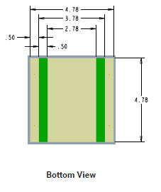
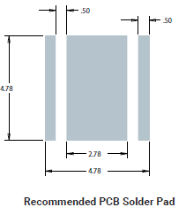
Yes it appears it needs to be soldered to an intermediate PCB. Dang! Another very significant via in the heat path. LED's mount surface is 4.78x4.478mm, but part of that is the two electrical connectors. I assume the fiberglass in a PCB has a high heat resistance. Oh, now I understand your CNC idea. That would give even less mount surface area: 4.78 x 2.78 mm, or so, but much better than via a PCB.
[img]cid:part1.EF664A6F.DC56A07D(at)gmail.com[/img][img]cid:part2.D741210D.62FCC22C(at)gmail.com[/img]
Yes, this thread is getting long. I guess I should have formulated my question much more clearly to begin with. Although I now have a better understanding of how the different parts of the heat path add up to a total heat resistance, the basic question is material thickness of plate the LED mounts to and the plate's contact area of the wing skin, formula for. Looking at the site and thread Ernest referred to. I think that gives me enough data to sensibly calculate mount plate thickness, how it should taper down and needed contact area with skin.
Finn
On 11/2/2020 7:07 AM, Rob Turk wrote:
| Quote: |
The XM-L2 are Surface mounted. Are you planning to do double-sided PCB and add via's under each LED, or do you plan on a CNC pattern in aluminium to allow direct contact to the LED base? The via's have their own thermal resistance to account for.
Rob
P.S. Cree now have the XM-L3 which tolerate even higher currents and deliver more lm/watt. Worth a look, I just used some in a strobe config.
| Quote: | Looking at the Cree XM-L2 with a thermal resistance of 2.5W/C from junction to mount surface. Add to that a conservative 0.5W/C for heat sink compound and we get 3W/C.
Max die temp is 150C. But unlimited life is 35C. It appears that when you go above 35C you start reducing life of the LED.
The LEDs are "binned" (color and efficiency determined) at 85C.
So lets set die temp of 85C as the design goal.
With built-in temp limiting, I think we can probably consider wing skin to air thermal resistance as 0W/C (air flowing over the skin in flight).
Consider 32C ambient we get 85 -3 -32 = 50 allowed temp difference from mount plate to skin.
Each LED has a mount surface of about 20x20mm.
If we have eight 10W LEDs at 30% efficiency, we need to get rid of 56 watts.
So max thermal resistance of mount plate and mount late to wing skin should be 56/50 = 1.1W/C. If we use heat sink compound between plate and wing skin, we're down to 0.6W/C max thermal resistance of the mount plate. Wow! Can that be right?
If alum has thermal resistance of 0.2 W/C we need 3 of something. What is the something? Thickness vs area? This is where I bog down.
Finn
Virus-free. www.avast.com [url=#DAB4FAD8-2DD7-40BB-A1B8-4E2AA1F9FDF2] [/url]
|
|
| | - The Matronics AeroElectric-List Email Forum - | | | Use the List Feature Navigator to browse the many List utilities available such as the Email Subscriptions page, Archive Search & Download, 7-Day Browse, Chat, FAQ, Photoshare, and much more:
http://www.matronics.com/Navigator?AeroElectric-List |
|
| Description: |
|
| Filesize: |
4.96 KB |
| Viewed: |
2934 Time(s) |
|
| Description: |
|
| Filesize: |
3.73 KB |
| Viewed: |
2934 Time(s) |
|
|
|
| Back to top |
|
|
finn.usa(at)gmail.com
Guest
|
| Posted: Mon Nov 02, 2020 9:20 am Post subject: DIY LED landing light -- Wing skin as heat sink? |
|
|
Thank you Ernest. This sentence "Copper Has a thermal conductivity of 401 W/(m K)" did it.
I thought the "m" stood for "milli" when I first Googled alum thermal resistance.. It's meters, think. In other words thickness.
So alum is 205 W/Meter K or W/Meter C.
Area apparently nulls out. Whether applying 1 W heat to 1 square meter or to 1 square mm it will still drop 205C per meter thickness. Right?
Intuitively the mount plate has to be at least as thick as half the widest edge of the LED base. Then can taper down as the area spreads out.
The Cree XM-L2 has an (inner) 4.78x2.78mm base. so 4.78 * 0.5 / 25.4 = 0.094" So your 0.09 plate thickness is close.
Let's assume a 0.035 sq in LED base on a 0.1" plate. That should expand out to about 0.14 sq in contact area with 0.025" skin. (0.1 /0.025)
On my RV-4 there would be about 1.5" or about 0.04m from LED to wing skins. Two of those, 0.02m. 0.02 x 205 =Â 4C/W.
Add to that 2.5 for LED junction to mount base. 0.5 mount base to plate and 0.5 mount base to wing skin and we get 7.5C/W.
7 W would result in a temp drop of 53 C from LED junction to wing skin, resulting in LED junction temp of 85C at 32C ambient, if my calculations are right.
With 8 LEDs the mount plate to wing contact should be 1.12 sq in. Easy with two 1/2" flanges x 2 to 3".
To implement this I would probably mount the LEDs on a 1/8" alum bar with groves milled for electical connectors. 2 rows of 4 LEDs. Adding reflectors is a whole other problem.
Actually the 100W 45mil Bridgelux LED chip might make it a lot simpler (40x40mm mount area). Sure the mount plate would be a lot thicker in the center ...
https://www.stratusleds.com/module
Finn
On 11/1/2020 9:08 PM, Ernest Christley wrote:
| Quote: | https://electronics.stackexchange.com/questions/294583/does-heatsink-transfer-plate-thickness-matter
I think the 4th answer down give the answer. Draw out the path of where you are inputting the heat (back of the module), to where air starts flowing over it.
If it were me, I'd mount it on an 0.80 or 0.90 plate and tape a thermocouple on the back. Maybe set a fan in front to simulate the prop turning. If not cool enough, use a thicker plate, or drill more holes.
On Sunday, November 1, 2020, 7:42:33 PM EST, Finn Lassen <finn.usa(at)gmail.com> (finn.usa(at)gmail.com) wrote:
On 11/1/2020 6:37 PM, Robert L. Nuckolls, III wrote:
| Quote: | | Quote: | | Quote: | Â Are we talking about landing lights?
 Bob . . . |
Yes landing lights.
|
 Okay . . . in the right pew now.
 Is there an engineering data spec sheet available
 for the device(s) you're considering?
 Do you know the thermal resistance from mounting
 surface to LED junction?
 Bob . . . |
Looking at the Cree XM-L2 with a thermal resistance of 2.5W/C from junction to mount surface. Add to that a conservative 0.5W/C for heat sink compound and we get 3W/C.
Max die temp is 150C. But unlimited life is 35C. It appears that when you go above 35C you start reducing life of the LED.
The LEDs are "binned" (color and efficiency determined)Â at 85C.
So lets set die temp of 85C as the design goal.
With built-in temp limiting, I think we can probably consider wing skin to air thermal resistance as 0W/C (air flowing over the skin in flight).
Consider 32C ambient we get 85 -3 -32 = 50 allowed temp difference from mount plate to skin.
Each LED has a mount surface of about 20x20mm.
If we have eight 10W LEDs at 30% efficiency, we need to get rid of 56 watts.
So max thermal resistance of mount plate and mount late to wing skin should be 56/50 = 1.1W/C. If we use heat sink compound between plate and wing skin, we're down to 0.6W/C max thermal resistance of the mount plate. Wow! Can that be right?
If alum has thermal resistance of 0.2 W/C we need 3 of something. What is the something? Thickness vs area? This is where I bog down.
Finn
Virus-free. www.avast.com [url=#DAB4FAD8-2DD7-40BB-A1B8-4E2AA1F9FDF2] [/url]
|
| | - The Matronics AeroElectric-List Email Forum - | | | Use the List Feature Navigator to browse the many List utilities available such as the Email Subscriptions page, Archive Search & Download, 7-Day Browse, Chat, FAQ, Photoshare, and much more:
http://www.matronics.com/Navigator?AeroElectric-List |
|
|
|
| Back to top |
|
|
matronics(at)rtist.nl
Guest
|
| Posted: Mon Nov 02, 2020 12:09 pm Post subject: DIY LED landing light -- Wing skin as heat sink? |
|
|
Since you are looking to get the most out of your design, I'd really recommend you look at the XLamp XM-L3 series. They are identical in size and shape, but have higher light output for the same current (approx +20%), they have lower thermal resistance (2.2 vs 2.5 DegC/W), and they can endure higher max current (5A vs 3A). You may be able to get the same output using 6 instead of 8 LEDs, which means a lot less losses and heat to deal with.
Only drawback I have seen is that they are not available in neutral white, only higher color temperatures.
On 11/2/2020 4:39 PM, Finn Lassen wrote:
| Quote: |
Thanks for pointing that out Rob. In my mind I had mixed up the 10W LEDs I got from mpja.com.
Yes it appears it needs to be soldered to an intermediate PCB. Dang! Another very significant via in the heat path. LED's mount surface is 4.78x4.478mm, but part of that is the two electrical connectors. I assume the fiberglass in a PCB has a high heat resistance. Oh, now I understand your CNC idea. That would give even less mount surface area: 4.78 x 2.78 mm, or so, but much better than via a PCB.
[img]cid:part1.4C5E714B.4F1AFD85(at)rtist.nl[/img][img]cid:part2.0E10A245.FEFDA9AA(at)rtist.nl[/img]
Yes, this thread is getting long. I guess I should have formulated my question much more clearly to begin with. Although I now have a better understanding of how the different parts of the heat path add up to a total heat resistance, the basic question is material thickness of plate the LED mounts to and the plate's contact area of the wing skin, formula for. Looking at the site and thread Ernest referred to. I think that gives me enough data to sensibly calculate mount plate thickness, how it should taper down and needed contact area with skin.
Finn
On 11/2/2020 7:07 AM, Rob Turk wrote:
| Quote: |
The XM-L2 are Surface mounted. Are you planning to do double-sided PCB and add via's under each LED, or do you plan on a CNC pattern in aluminium to allow direct contact to the LED base? The via's have their own thermal resistance to account for.
Rob
P.S. Cree now have the XM-L3 which tolerate even higher currents and deliver more lm/watt. Worth a look, I just used some in a strobe config.
|
|
| | - The Matronics AeroElectric-List Email Forum - | | | Use the List Feature Navigator to browse the many List utilities available such as the Email Subscriptions page, Archive Search & Download, 7-Day Browse, Chat, FAQ, Photoshare, and much more:
http://www.matronics.com/Navigator?AeroElectric-List |
|
| Description: |
|
| Filesize: |
4.96 KB |
| Viewed: |
2929 Time(s) |

|
| Description: |
|
| Filesize: |
3.73 KB |
| Viewed: |
2929 Time(s) |

|
|
|
| Back to top |
|
|
finn.usa(at)gmail.com
Guest
|
| Posted: Mon Nov 02, 2020 6:18 pm Post subject: DIY LED landing light -- Wing skin as heat sink? |
|
|
On 11/2/2020 6:05 PM, Ernest Christley wrote:
| Quote: | As for reflectors, are they really needed? The LED has a light pattern that puts nearly all of the light forward to begin with. And LEDs with a 45 degree pattern are available. The ones I used from MPJA had a 160 degree spread, but a chart of the intensity showed very little at the ends of that range.
|
Well, my goal is to light up at least 1,000 feet of the runway, preferably 3,000.
Charlie referred to a landing light with a 3 degree beam width.
I guess with a strong enough LED (like 100W or 9,000 lumens) the bean width may not be all that important.
For the reflector for the https://www.stratusleds.com/module is "the beam is around 15 degrees with a soft falloff".
But definitely a good point.
Finn
Virus-free. www.avast.com [url=#DAB4FAD8-2DD7-40BB-A1B8-4E2AA1F9FDF2] [/url]
| | - The Matronics AeroElectric-List Email Forum - | | | Use the List Feature Navigator to browse the many List utilities available such as the Email Subscriptions page, Archive Search & Download, 7-Day Browse, Chat, FAQ, Photoshare, and much more:
http://www.matronics.com/Navigator?AeroElectric-List |
|
|
|
| Back to top |
|
|
|
|
You cannot post new topics in this forum
You cannot reply to topics in this forum
You cannot edit your posts in this forum
You cannot delete your posts in this forum
You cannot vote in polls in this forum
You cannot attach files in this forum
You can download files in this forum
|
Powered by phpBB © 2001, 2005 phpBB Group
|

