 |
Matronics Email Lists
Web Forum Interface to the Matronics Email Lists
|
| View previous topic :: View next topic |
| Author |
Message |
farmrjohn
Joined: 31 Dec 2018
Posts: 54
|
 Posted: Tue Mar 22, 2022 1:48 pm Post subject: Voltage Regulator Questions Posted: Tue Mar 22, 2022 1:48 pm Post subject: Voltage Regulator Questions |
 |
|
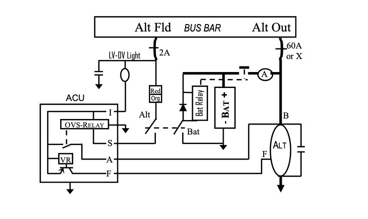
I have a Zeftronics R15V00-A regulator controlling a Hartzel/Plane Power 60 amp alternator and am trying to troubleshoot the alternator dropping off line.  The regulator is connected to the alternator and bus per their wiring diagram with no indicator lamp connected to pin I.  The connections utilized the existing wiring, dating to 1994 at the latest, and 1966 at the earliest (externally braid shielded wire with faston connectors for the regulator pins) and feel a bit loose on the regulator pins.  The S and A wires also attach to noise suppressors.  I'm considering replacing the wiring to have new faston sockets.


1.  Can the regulator be wired as in the Z-11 diagram with pins S and A jumped together from the alternator switch?


2.  Does the regulator need the external indicator lamp connected to function properly?


3.  Do the wires to the regulator pins need to be shielded/grounded as they are now?  If so, will the currently available jacketed/shielded wire be an adequate replacement?


4.  Are the noise suppressors necessary or can they be eliminated?  There is currently no alternator "whine" in the radio.


John
| | - The Matronics AeroElectric-List Email Forum - | | | Use the List Feature Navigator to browse the many List utilities available such as the Email Subscriptions page, Archive Search & Download, 7-Day Browse, Chat, FAQ, Photoshare, and much more:
http://www.matronics.com/Navigator?AeroElectric-List |
|
| Description: |
|
| Filesize: |
50.55 KB |
| Viewed: |
3240 Time(s) |
|
|
|
| Back to top |
|
 |
stuart(at)stuarthutchison
Guest
|
| Posted: Tue Mar 22, 2022 2:38 pm Post subject: Voltage Regulator Questions |
|
|
G’day John.
Less than ‘gas tight’ electrical connections are a common issue and with loose faston connectors and an intermittent issue, perhaps a cheap test is to squeeze the fastons slightly with pliers to improve their grip. Be careful not to over do it, as they’ll be too tight to put on and the temptation is to use a tapered screwdriver to open them up again, potentially misaligning the sides to the point where already limited contact area is reduced. Costs little in time and might do the trick.
Kind regards, Stuart
| Quote: | On 23 Mar 2022, at 8:48 am, farmrjohn <faithvineyard(at)yahoo.com> wrote:
I have a Zeftronics R15V00-A regulator controlling a Hartzel/Plane Power 60 amp alternator and am trying to troubleshoot the alternator dropping off line. The regulator is connected to the alternator and bus per their wiring diagram with no indicator lamp connected to pin I. The connections utilized the existing wiring, dating to 1994 at the latest, and 1966 at the earliest (externally braid shielded wire with faston connectors for the regulator pins) and feel a bit loose on the regulator pins. The S and A wires also attach to noise suppressors. I'm considering replacing the wiring to have new faston sockets.
1. Can the regulator be wired as in the Z-11 diagram with pins S and A jumped together from the alternator switch?
2. Does the regulator need the external indicator lamp connected to function properly?
3. Do the wires to the regulator pins need to be shielded/grounded as they are now? If so, will the current jacketed/shielded wire be adequate?
4. Are the noise suppressors necessary or can they be eliminated? There is currently no alternator "whine" in the radio.
John
Read this topic online here:
http://forums.matronics.com/viewtopic.php?p=506369#506369
Attachments:
http://forums.matronics.com//files/zeftronics_r15v00_documentation_593.pdf
|
| | - The Matronics AeroElectric-List Email Forum - | | | Use the List Feature Navigator to browse the many List utilities available such as the Email Subscriptions page, Archive Search & Download, 7-Day Browse, Chat, FAQ, Photoshare, and much more:
http://www.matronics.com/Navigator?AeroElectric-List |
|
|
|
| Back to top |
|
|
user9253
Joined: 28 Mar 2008
Posts: 1908
Location: Riley TWP Michigan
|
| Posted: Tue Mar 22, 2022 5:37 pm Post subject: Re: Voltage Regulator Questions |
|
|
1. No, the 2 amp fuse or circuit breaker might blow or trip when the regulator is outputting 3 or 4 amps.

2. No, I don't think the regulator would be designed to shut down when the lamp burns out.

3. No, I don't think that shielded wires are necessary.

4. Whine is usually caused by a bad diode.  The capacitors are probably not doing much good.  But they aren't hurting anything.  So why remove them?

5.  I agree with Stuart.  The problem is most likely a bad connection.  Make them tight.  It is highly unlikely that wires are the problem.  Just fix the terminations.
| | - The Matronics AeroElectric-List Email Forum - | | | Use the List Feature Navigator to browse the many List utilities available such as the Email Subscriptions page, Archive Search & Download, 7-Day Browse, Chat, FAQ, Photoshare, and much more:
http://www.matronics.com/Navigator?AeroElectric-List |
|
_________________
Joe Gores |
|
| Back to top |
|
|
chaskuss(at)yahoo.com
Guest
|
| Posted: Tue Mar 22, 2022 7:16 pm Post subject: Voltage Regulator Questions |
|
|
Along with Stewart's comments, be sure to only use the PIDG [Plastic Insulated Diamond Grip] connectors that Bob N advocates. These are much higher quality than the crap that is sold in auto parts stores. I've found that Waytek Wire and SteinAir usually have the best prices on these. You can differentiate between garbage [PVC insulator and it only crimps to the bare wire] and PIDG [ uses Nylon insulation and allows you to crimp both the bare wire and the insulation behind it. That second crimp gives the wire support so that vibration will not fracture the wire, where it enters the insulation.
On Tuesday, March 22, 2022, 10:08:39 PM EDT, Stuart Hutchison <stuart(at)stuarthutchison.com.au> wrote:
--> AeroElectric-List message posted by: Stuart Hutchison <stuart(at)stuarthutchison.com.au (stuart(at)stuarthutchison.com.au)>
G’day John.
Less than ‘gas tight’ electrical connections are a common issue and with loose faston connectors and an intermittent issue, perhaps a cheap test is to squeeze the fastons slightly with pliers to improve their grip. Be careful not to over do it, as they’ll be too tight to put on and the temptation is to use a tapered screwdriver to open them up again, potentially misaligning the sides to the point where already limited contact area is reduced. Costs little in time and might do the trick.
Kind regards, Stuart
| Quote: | I have a Zeftronics R15V00-A regulator controlling a Hartzel/Plane Power 60 amp alternator and am trying to troubleshoot the alternator dropping off line. The regulator is connected to the alternator and bus per their wiring diagram with no indicator lamp connected to pin I. The connections utilized the existing wiring, dating to 1994 at the latest, and 1966 at the earliest (externally braid shielded wire with faston connectors for the regulator pins) and feel a bit loose on the regulator pins. The S and A wires also attach to noise suppressors. I'm considering replacing the wiring to have new faston sockets.
|
| Quote: | 1. Can the regulator be wired as in the Z-11 diagram with pins S and A jumped together from the alternator switch?
|
| Quote: | 2. Does the regulator need the external indicator lamp connected to function properly?
|
| Quote: | 3. Do the wires to the regulator pins need to be shielded/grounded as they are now? If so, will the current jacketed/shielded wire be adequate?
|
| Quote: | 4. Are the noise suppressors necessary or can they be eliminated? There is currently no alternator "whine" in the radio.
|
| Quote: | Read this topic online here:
|
http://www.matronics.com/Navigator?AeroElectric-List
http://forums.matronics.com
http://wiki.sp; &= -->
| | - The Matronics AeroElectric-List Email Forum - | | | Use the List Feature Navigator to browse the many List utilities available such as the Email Subscriptions page, Archive Search & Download, 7-Day Browse, Chat, FAQ, Photoshare, and much more:
http://www.matronics.com/Navigator?AeroElectric-List |
|
|
|
| Back to top |
|
|
farmrjohn
Joined: 31 Dec 2018
Posts: 54
|
| Posted: Wed Mar 23, 2022 7:43 am Post subject: Re: Voltage Regulator Questions |
|
|
Thanks all for the replies.


To clarify question 1 about combining the A and S lead, the circuit breaker protection is a 5 amp fuse vs. the 2 amp shown on the diagram, which is consistent with Zeftronics instructions.  In that case would it be OK to combine per the Z-11 diagram?


I was asking about replacing the wire because there really isn't that much available extra length on the existing to replace the existing faston connectors. I do have the pidg connectors.


John
| | - The Matronics AeroElectric-List Email Forum - | | | Use the List Feature Navigator to browse the many List utilities available such as the Email Subscriptions page, Archive Search & Download, 7-Day Browse, Chat, FAQ, Photoshare, and much more:
http://www.matronics.com/Navigator?AeroElectric-List |
|
|
|
| Back to top |
|
|
user9253
Joined: 28 Mar 2008
Posts: 1908
Location: Riley TWP Michigan
|
| Posted: Wed Mar 23, 2022 8:39 am Post subject: Re: Voltage Regulator Questions |
|
|
About jumping terminals "A" and "S" together:  The short answer is yes.  The long answer is:

Those two terminals already do get connected together when the alternator switch is on.  The path is from terminal "A" to the alternator "B" lead, to the 60 amp current limiter, to the main power bus, through the small fuse to the alternator switch, to terminal "S".  Since the 2 amp fuse has been replaced with a 5 amp fuse, terminals "A" and "S" can be jumped together and the wire from "A" to "B" can be removed.  Everything should work fine for a few years.  There could be a future problem if resistance develops due to corrosion in the circuit between the main power bus and terminal "S".  The voltage dropped across that resistance will be greater now that the circuit is also carrying alternator field current.  The voltage regulator will then sense a lower voltage than bus voltage.  And the voltage regulator will increase field current to increase the voltage on terminal "S".  This will result in over voltage on the main power bus.   During the annual condition inspection, measure the voltage drop while under load between the main power bus and voltage regulator terminal "S".
| | - The Matronics AeroElectric-List Email Forum - | | | Use the List Feature Navigator to browse the many List utilities available such as the Email Subscriptions page, Archive Search & Download, 7-Day Browse, Chat, FAQ, Photoshare, and much more:
http://www.matronics.com/Navigator?AeroElectric-List |
|
_________________
Joe Gores |
|
| Back to top |
|
|
user9253
Joined: 28 Mar 2008
Posts: 1908
Location: Riley TWP Michigan
|
| Posted: Wed Mar 23, 2022 10:18 am Post subject: Re: Voltage Regulator Questions |
|
|
Oops, I was wrong. Looking at the schematic in post #1 above, it is not clear how the relay is wired. So I take back what I said about terminals "A" and "S" already being connected together when the alternator switch is turned on.
| | - The Matronics AeroElectric-List Email Forum - | | | Use the List Feature Navigator to browse the many List utilities available such as the Email Subscriptions page, Archive Search & Download, 7-Day Browse, Chat, FAQ, Photoshare, and much more:
http://www.matronics.com/Navigator?AeroElectric-List |
|
_________________
Joe Gores |
|
| Back to top |
|
|
nuckolls.bob(at)aeroelect
Guest
|
| Posted: Thu Mar 24, 2022 10:26 am Post subject: Voltage Regulator Questions |
|
|
At 04:48 PM 3/22/2022, you wrote:
| Quote: | --> AeroElectric-List message posted by: "farmrjohn" <faithvineyard(at)yahoo.com>
I have a Zeftronics R15V00-A regulator controlling a Hartzel/Plane Power 60 amp alternator and am trying to troubleshoot the alternator dropping off line. |
Does it ever produce significant output
over a period of time?
Are you replacing a regulator that once worked?
| Quote: | | The regulator is connected to the alternator and bus per their wiring diagram with no indicator lamp connected to pin I. |
There are a variety of almost-cloned, 'ford'
regulators out there. The original designs
in both electro-mechanical and solid-state
depended on continuity to the bus through
the warning light to bring the alternator on
line. I don't think that is true of any
modern, solid state incarnations of the 'ford'
electro-mechanical alternator regulators.
| Quote: | | The connections utilized the existing wiring, dating to 1994 at the latest, and 1966 at the earliest (externally braid shielded wire with faston connectors for the regulator pins) and feel a bit loose on the regulator pins. The S and A wires also attach to noise suppressors. I'm considering replacing the wiring to have new faston sockets. |
New PIDG fast-ons are never a bad idea especially
on older airplanes.
| Quote: | | 1. Can the regulator be wired as in the Z-11 diagram with pins S and A jumped together from the alternator switch? |
Yes. In fact recommended.
| Quote: | | 2. Does the regulator need the external indicator lamp connected to function properly? |
Probably not . . .
| Quote: | | 3. Do the wires to the regulator pins need to be shielded/grounded as they are now? If so, will the current jacketed/shielded wire be adequate? |
Shielding is of no demonstrable value anywhere
in any alternator or generator installation.
| Quote: | | 4. Are the noise suppressors necessary or can they be eliminated? There is currently no alternator "whine" in the radio. |
Noise filters same, same. Noise suppressors are
an artifact from systems that included electro-mechanical
regulators, generators and ADF receivers. All
that stuff is gone. Filters need to go with
them.
It would be useful to monitor the FIELD voltage while
observing system functionality. This will clue you
in as to whether its the regulator or the alternator
that is misbehaving.
I've been a bit out-of-pocket on the List for the
past several weeks. Got into an argument with a
band saw and you know who won. Had a bit of hand
surgery that is healing nicely and I'm able to
shed the cast and use the keyboard again.
Just finished refurbishing a vintage Milwaukee-Delta
bandsaw and I guess it needed 'blessing' with
a bit of blood sacrifice. Really nice saw!
Bob . . .
Un impeachable logic: George Carlin asked, "If black boxes
survive crashes, why don't they make the whole airplane
out of that stuff?"
| | - The Matronics AeroElectric-List Email Forum - | | | Use the List Feature Navigator to browse the many List utilities available such as the Email Subscriptions page, Archive Search & Download, 7-Day Browse, Chat, FAQ, Photoshare, and much more:
http://www.matronics.com/Navigator?AeroElectric-List |
|
|
|
| Back to top |
|
|
nuckolls.bob(at)aeroelect
Guest
|
| Posted: Thu Mar 24, 2022 10:30 am Post subject: Voltage Regulator Questions |
|
|
At 01:18 PM 3/23/2022, you wrote:
| Quote: | --> AeroElectric-List message posted by: "user9253" <fransew(at)gmail.com>
Oops, I was wrong. Looking at the schematic in post #1 above, it is not clear how the relay is wired. So I take back what I said about terminals "A" and "S" already being connected together when the alternator switch is turned on.
--------
Joe Gores
|
The original functions for "I", "A" and "S" terminals
on the 'ford' regulators are lost to antiquity.
For powering up a two terminal ("F" and "B")
alternator, you and almost always wire per
the Z-figures as long as your o.v. protection
system is independent of the regulator.
What kind of ov management device is included
on this airplane?
Bob . . .
Un impeachable logic: George Carlin asked, "If black boxes
survive crashes, why don't they make the whole airplane
out of that stuff?"
| | - The Matronics AeroElectric-List Email Forum - | | | Use the List Feature Navigator to browse the many List utilities available such as the Email Subscriptions page, Archive Search & Download, 7-Day Browse, Chat, FAQ, Photoshare, and much more:
http://www.matronics.com/Navigator?AeroElectric-List |
|
|
|
| Back to top |
|
|
farmrjohn
Joined: 31 Dec 2018
Posts: 54
|
| Posted: Thu Mar 24, 2022 1:56 pm Post subject: Re: Voltage Regulator Questions |
|
|
[quote="nuckolls.bob(at)aeroelect"]At 04:48 PM 3/22/2022, you wrote:
| Quote: | --> AeroElectric-List message posted by: "farmrjohn" <faithvineyard>
Does it ever produce significant output
over a period of time?
Immediately after engine start and turning alternator on will have 16 amp charge, quickly dropping back to 0 to .1 after the battery is recharged. When the alternator drops off after about 30 to 40 minutes of operation the discharge load is -10 amps until I load shed.
Are you replacing a regulator that once worked?
No. The alternator is new, replaced 20 hours ago.
There are a variety of almost-cloned, 'ford'
regulators out there. The original designs
in both electro-mechanical and solid-state
depended on continuity to the bus through
the warning light to bring the alternator on
line. I don't think that is true of any
modern, solid state incarnations of the 'ford'
electro-mechanical alternator regulators.
From Zeftronis’s linstructions the indicator light is illuminated by powere from the A pin if the S pin is unpowered via the over voltage protection. Once pin S is powered the power path to pin I is not available. I can attach that information when I get back home to my computer.
| Quote: | | I'm considering replacing the wiring to have new faston sockets. |
New PIDG fast-ons are never a bad idea especially
on older airplanes.
| Quote: | | 1. Can the regulator be wired as in the Z-11 diagram with pins S and A jumped together from the alternator switch? |
Yes. In fact recommended.
Confirming it should be 20 ga per the Z-11 diagram?
It would be useful to monitor the FIELD voltage while
observing system functionality. This will clue you
in as to whether its the regulator or the alternator
that is misbehaving.
Would that be the monitor diagram (Z-23)?
I've been a bit out-of-pocket on the List for the
past several weeks. Got into an argument with a
band saw and you know who won. Had a bit of hand
surgery that is healing nicely and I'm able to
shed the cast and use the keyboard again.
Just finished refurbishing a vintage Milwaukee-Delta
bandsaw and I guess it needed 'blessing' with
a bit of blood sacrifice. Really nice saw!
Sorry to hear that, the machinery and mechanizing gods do like their blood sacrifices. Heal well.
John
" |
| | - The Matronics AeroElectric-List Email Forum - | | | Use the List Feature Navigator to browse the many List utilities available such as the Email Subscriptions page, Archive Search & Download, 7-Day Browse, Chat, FAQ, Photoshare, and much more:
http://www.matronics.com/Navigator?AeroElectric-List |
|
|
|
| Back to top |
|
|
chaskuss(at)yahoo.com
Guest
|
| Posted: Sat Mar 26, 2022 10:47 am Post subject: Voltage Regulator Questions |
|
|
Bob & Listers,


 The original [ 1960s]  meaning of the Ford mechanical voltage regulator 4 terminal ID letters was:


I =  Ignition         connected to ignition power thru the instrument panel idiot light


A = Ammeter       used when instrument panel had an ammeter rather than an idiot light


S = Stator            connected to alternator stator terminal


F = Field              connected to alternator field terminal


On Friday, March 25, 2022, 02:51:00 AM EDT, Robert L. Nuckolls, III <nuckolls.bob(at)aeroelectric.com> wrote:

snipped


  The original functions for "I", "A" and "S" terminals

  on the 'ford' regulators are lost to antiquity.

  snipped


  Bob . . .


  Un impeachable logic: George Carlin asked, "If black boxes

  survive crashes, why don't they make the whole airplane

  out of that stuff?"
| | - The Matronics AeroElectric-List Email Forum - | | | Use the List Feature Navigator to browse the many List utilities available such as the Email Subscriptions page, Archive Search & Download, 7-Day Browse, Chat, FAQ, Photoshare, and much more:
http://www.matronics.com/Navigator?AeroElectric-List |
|
|
|
| Back to top |
|
|
nuckolls.bob(at)aeroelect
Guest
|
| Posted: Sun Mar 27, 2022 9:40 am Post subject: Voltage Regulator Questions |
|
|
At 10:43 AM 3/23/2022, you wrote:
| Quote: | --> AeroElectric-List message posted by: "farmrjohn" <faithvineyard(at)yahoo.com>
|
John,
Forgive me . . . I've been heavily distracted
by less interesting matters and didn't stay
well connected with this thread. Help
me catch up.
I had asked about history and I thought I saw
a reply on that query but somehow it got
snuffed in my email app before I read it.
Are there unresolved issues?
Bob . . .
Un impeachable logic: George Carlin asked, "If black boxes
survive crashes, why don't they make the whole airplane
out of that stuff?"
| | - The Matronics AeroElectric-List Email Forum - | | | Use the List Feature Navigator to browse the many List utilities available such as the Email Subscriptions page, Archive Search & Download, 7-Day Browse, Chat, FAQ, Photoshare, and much more:
http://www.matronics.com/Navigator?AeroElectric-List |
|
|
|
| Back to top |
|
|
farmrjohn
Joined: 31 Dec 2018
Posts: 54
|
| Posted: Mon Mar 28, 2022 1:38 pm Post subject: Re: Voltage Regulator Questions |
|
|
| nuckolls.bob(at)aeroelect wrote: | At 10:43 AM 3/23/2022, you wrote:
| Quote: | --> AeroElectric-List message posted by: "farmrjohn" <faithvineyard>
|
John,
Forgive me . . . I've been heavily distracted
by less interesting matters and didn't stay
well connected with this thread. Help
me catch up.
I had asked about history and I thought I saw
a reply on that query but somehow it got
snuffed in my email app before I read it.
Are there unresolved issues?
Bob . . .
Un impeachable logic: George Carlin asked, "If black boxes
survive crashes, why don't they make the whole airplane
out of that stuff?" |
I had answered your questions in post 10 above (March 24). So far we have not changed the wiring from the Zeftronics diagram since it's a certificated airplane and are evaluating if that would be a minor or major alteration. We did clean and lightly tighten the existing faston connectors and applied some dielectric grease and it's worked OK for two flights now.
John
| | - The Matronics AeroElectric-List Email Forum - | | | Use the List Feature Navigator to browse the many List utilities available such as the Email Subscriptions page, Archive Search & Download, 7-Day Browse, Chat, FAQ, Photoshare, and much more:
http://www.matronics.com/Navigator?AeroElectric-List |
|
|
|
| Back to top |
|
|
|
|
You cannot post new topics in this forum
You cannot reply to topics in this forum
You cannot edit your posts in this forum
You cannot delete your posts in this forum
You cannot vote in polls in this forum
You cannot attach files in this forum
You can download files in this forum
|
Powered by phpBB © 2001, 2005 phpBB Group
|

