 |
Matronics Email Lists
Web Forum Interface to the Matronics Email Lists
|
| View previous topic :: View next topic |
| Author |
Message |
bobair(at)me.com
Guest
|
 Posted: Sun Jan 23, 2011 11:32 am Post subject: Comm Antenna & SWR Reading -- Too High? Posted: Sun Jan 23, 2011 11:32 am Post subject: Comm Antenna & SWR Reading -- Too High? |
 |
|
Bob, et al,


I'm upgrading/replacing the instrument panel in my GlaStar.  Part of the project includes the installation of a Comant CI-122 "bent whip" antenna on the belly under the baggage compartment area.  This antenna will be my "Comm 1" antenna and will be connected to a Garmin 430W.  Because of the composite fuselage, I installed a 24" x 36" Al ground plane in the belly.  The antenna is positioned so that the entire antenna is "covered" by the ground plane (i.e., the antenna base is mounted about 12" from the long-axis end of the ground plane.  The antenna is connected (and bonded) to the ground plane with the four stainless machine screws used to mount the antenna.


A friend who is a ham/EE/PE tested this antenna for SWR and he wasn't very encouraged by the results.  Here are the data:


Equipment:


Bird Watt Meter with (slug?) 5C at 5W, 100 - 250 Mhz

100W Dummy Load:  Decibel DB4303G

We used my Yaesu handheld as the transmitter.

Everything was coupled together with BNC connectors.


Test 1:  122.9 MHz (the CTAF at my base):  	Forward Power:  0.8;  Reverse Power:  0.43;  VSWR 6.5

Test 2:  125.0 MHz						Forward Power:  0.8;  Reverse Power:  0.4;	VSWR 5.8

Test 3:  130.0 MHz						Forward Power:  0.8;  Reverse Power:  0.4;	VSWR 5.8


We checked the resistance between the four mounting screws and the outside (ground?) of a BNC connector connected to the antenna.  The resistances were all ~0.1 Ohm.  The Bird meter was connected directly to the antenna BNC through my buddy's feedline which appeared to be about 4 feet long.  I don't know what type of coax he used.  (The feedline for this antenna to the 430W will be RG-400.)  The test was done in a closed metal hangar.  Would that or the proximity of the antenna to the concrete hangar floor affect the results?


What's your take on this?  Should the SWR be significantly lower for good performance (I plan on flying this plane in IMC)?  Are there things that I should/could do to improve performance before I put the baggage compartment structure back in and make things much less accessible?  Or should this installation/SWR readings indicate acceptable performance?  With these SWR readings, will the reflected power cause any damage to the Garmin 430W?


Does testing the SWR of a "cat's-whisker" VOR/Loc/GS antenna make sense?  I installed one of those, as well, but the feedline (the yellow tri-ax that comes with GlaStars) wasn't terminated on the radio end.  If it makes sense to do so, I can go back and test it after I've terminated that feedline.


Thanks in advance.


Best regards,


Bob Falstad

GlaStar N248BF

~310 Hours
| | - The Matronics AeroElectric-List Email Forum - | | | Use the List Feature Navigator to browse the many List utilities available such as the Email Subscriptions page, Archive Search & Download, 7-Day Browse, Chat, FAQ, Photoshare, and much more:
http://www.matronics.com/Navigator?AeroElectric-List |
|
|
|
| Back to top |
|
 |
nuckolls.bob(at)aeroelect
Guest
|
| Posted: Sun Jan 23, 2011 2:03 pm Post subject: Comm Antenna & SWR Reading -- Too High? |
|
|
Test 1: 122.9 MHz (the CTAF at my base): Forward Power: 0.8; Reverse Power: 0.43; VSWR 6.5
Test 2: 125.0 MHz Forward Power: 0.8; Reverse Power: 0.4; VSWR 5.8
Test 3: 130.0 MHz Forward Power: 0.8; Reverse Power: 0.4; VSWR 5.8
We checked the resistance between the four mounting screws and the outside (ground?) of a BNC connector connected to the antenna. The resistances were all ~0.1 Ohm. The Bird meter was connected directly to the antenna BNC through my buddy's feedline which appeared to be about 4 feet long. I don't know what type of coax he used. (The feedline for this antenna to the 430W will be RG-400.) The test was done in a closed metal hangar. Would that or the proximity of the antenna to the concrete hangar floor affect the results?
Some but I don't think all that much.
What's your take on this? Should the SWR be significantly lower for good performance (I plan on flying this plane in IMC)? Are there things that I should/could do to improve performance before I put the baggage compartment structure back in and make things much less accessible? Or should this installation/SWR readings indicate acceptable performance?
Could be. We need to consider the effects of making
measurements on the transmitter end of a piece of coax
when studying the characteristics of a particular
load (antenna).
The only time a piece of coax will show 1:1 SWR is
when the OTHER end is terminated in a load having the
same characteristic impedance. In this case 50 ohms
resistive and no reactive component.
Consider also that the antenna's characteristics
measured at the base may never be exactly 50 ohms
and it may include reactive components (inductance/
capacitance) as well.
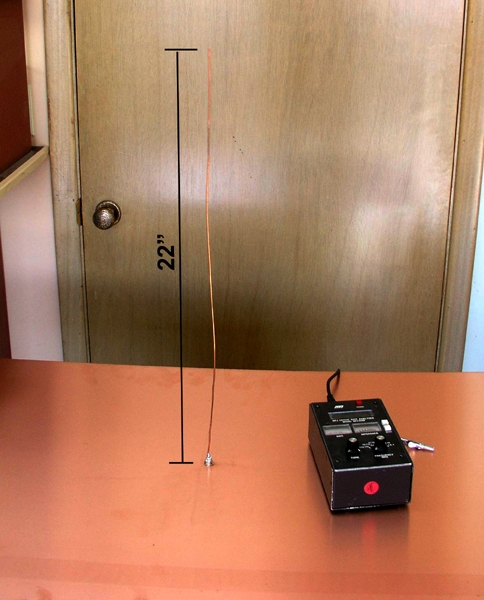
Just went to the bench and fabricated this test
article.
[img]cid:.0[/img]
It's 22" of 12AWG copper soldered to a BNC chassis connector
mounted to approximate center of a copper sheet 24 x 36
inches.
The investigative instrument of choice is the MFJ-259
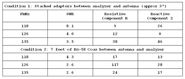
antenna analyzer. Here is a chart of measurement results:
[img]cid:.1[/img]
A fine wire, 1/4 wave radiator has a resonance base impedance that
is quite low. As you can see, at 126 MHz and minimized feedline,
the reactive component of this antenna went down to 0 ohms (resonance)
and the resistive component was about 12 ohms. Hmmm . . . 12/50
explains the 4:1 SWR reading that was observed. So in terms of best
performance (resonance) this antenna is rather crippled for accepting
all the power that a 50 ohm feedline has to offer.
At the extreme ends of the comm band, the reactive and resistive
components did their expected hat dances with SWR readings that
never got better than about 3:1 at any frequency.
Okay, let's put a piece of "test coax" between the antenna and
instrument. SWR figures got better over the range of interest although
resistive and reactive components became a bit more agitated.
This is because of the effects of frequency on a mismatched
piece of coax can be profound in terms of what is viewed
looking into the same end as your transceiver. We take advantage
of these "transforming" effects offered by mis-matched transmission
lines but in the case before us, there's no particular advantage
to be gained. The question to be answered is "how much practical
difference does it make?"
Interestingly enough, the longer a transmission line, the
BETTER things get. This is because of losses in the line.
You can hook your transponder to one end of a 1000' spool
of the best coax out there and it wouldn't know if the
other end was open, shorted, or had a good antenna on it.
Even if there WAS a good antenna on it, no practical amount
of energy would even reach it due to transmission line
losses.
So back to your quest and questions:
The effective testing for antenna systems generaly
assumes that the antenna itself is okay. It MAY have some
pretty squirrely characteristics . . . but that's how
monopole-quarterwave antennas are. So is your
feedline good? Put a dummy load on the antenna end of
the feedline and check SWR over frequency range of interest
from the transceiver end.
Since you've terminated the feedline in a value it
LIKES, the SWR should be 1:1 over full frequency
range. If the feed path is compromised with opens
or shorts, the SWR will not be 1:1 at any frequency
and will wobble all over the place as frequency
changes.
But if the antenna is not damaged, the mounting
hardware is tight, the ground-plane moderately
adequate, then consider it good.
Now, it is useful to make SWR observations over
range of interest when the installation is new
and write them down. Use them as a benchmark for
future reference if you ever have a reason to
question antenna performance.
With these SWR readings, will the reflected power cause any damage to the Garmin 430W?
No. Modern transceivers have built in protection for
poor performing loads . . . up to and including shorted
and open transmission lines.
Does testing the SWR of a "cat's-whisker" VOR/Loc/GS antenna make sense?
Sure. But keep in mind that SWR is a measure of the antenna's
ability to accept/deliver energy and says nothing about
operational performance. I've seen antennas with 'terrible'
SWR out-perform antennas with 'excellent' swr but for reasons
other than impedance matching. Do separate dummy loaded
and antenna loaded measurements of the as-installed antenna
and associated feedline.
Hooking any sort of analyzer to the antenna itself will
yield good data but it will be data that has little or
no significance in terms of performance.
Given what we know of your system based on data you cited,
I have no reason to suspect that anything is amiss. It
would be good to get forward/reverse power measurements
of the as-installed antenna and feedline. Check THESE
numbers against manufacturer's limits in the installation
manual.
A caveat: Your own results may vary. Some commercial
antennas MAY have impedance transformation networks built
in that are intended to improve power transfer over the
range of interest. Further, the test I just demonstrated
is a fine-wire antenna . . . sharply resonant compared to
say a piece of 1/2" tubing which would be broader (and
harder to mount plus more drag) Shark fin antennas on
air-transport category airplanes have impedance matching
in the base and 'broadness' in the radiating components.
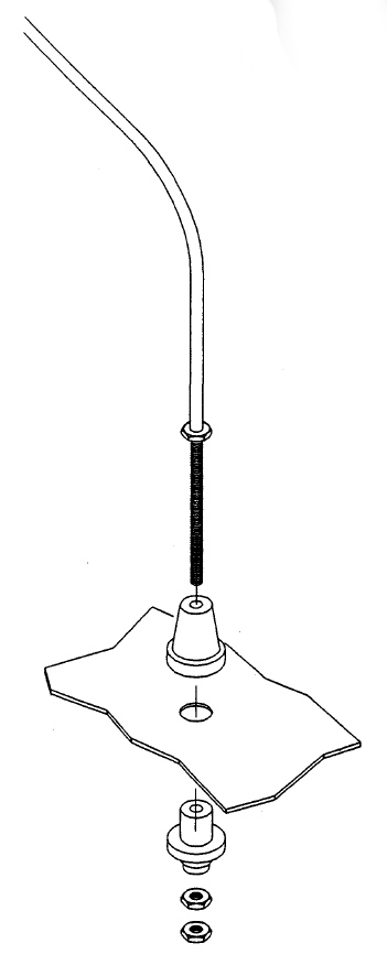
Finally, keep in mind that Cessna and others fitted their
products with antennas that looked a lot like this:
[img]cid:.2[/img]
Tens of thousands of antennas went out the factory
doors with this or similar configuration. This was
in a time when radios were MUCH less capable in terms
of sensitivity and signal/noise ratio of modern
avionics.
The upshot is that it's more important to BE CONNECTED
to what ever antenna you have than it is to massage
measured or perceived performance. No antenna is bad,
any antenna is probably good.
Bob . . .
| | - The Matronics AeroElectric-List Email Forum - | | | Use the List Feature Navigator to browse the many List utilities available such as the Email Subscriptions page, Archive Search & Download, 7-Day Browse, Chat, FAQ, Photoshare, and much more:
http://www.matronics.com/Navigator?AeroElectric-List |
|
| Description: |
|
| Filesize: |
204.15 KB |
| Viewed: |
7779 Time(s) |
|
| Description: |
|
| Filesize: |
59.78 KB |
| Viewed: |
7779 Time(s) |
|
| Description: |
|
| Filesize: |
44.48 KB |
| Viewed: |
7779 Time(s) |
|
|
|
| Back to top |
|
|
nuckolls.bob(at)aeroelect
Guest
|
| Posted: Sun Jan 23, 2011 7:07 pm Post subject: Comm Antenna & SWR Reading -- Too High? |
|
|
At 02:27 PM 1/23/2011, you wrote:
| Quote: |
Bob, et al,
I'm upgrading/replacing the instrument panel in my GlaStar. Part of
the project includes the installation of a Comant CI-122 "bent whip"
antenna on the belly under the baggage compartment area.
|
I did some searching for manufacturer's specs on the
CI-122 and found VSWR specs of both 2:1 and 3:1 maximum.
These kinds of figures imply some sort of impedance matching
hardware in the base of the antenna. It would be interesting
to do an ohmmeter test from center pin on the antenna's connector
and ground. If is shows a 'short', I suspect that some sort
of matching system is installed.
If that's true, then the values you were reading for
the tests are perhaps more worrisome. Get your ohmmeter
out an take a peek.
Bob . . .
| | - The Matronics AeroElectric-List Email Forum - | | | Use the List Feature Navigator to browse the many List utilities available such as the Email Subscriptions page, Archive Search & Download, 7-Day Browse, Chat, FAQ, Photoshare, and much more:
http://www.matronics.com/Navigator?AeroElectric-List |
|
|
|
| Back to top |
|
|
deej(at)deej.net
Guest
|
| Posted: Sun Jan 23, 2011 7:27 pm Post subject: Comm Antenna & SWR Reading -- Too High? |
|
|
On 1/23/2011 2:27 PM, Bob Falstad wrote:
| Quote: |
Test 1: 122.9 MHz (the CTAF at my base): Forward Power: 0.8; Reverse Power: 0.43; VSWR 6.5
Test 2: 125.0 MHz Forward Power: 0.8; Reverse Power: 0.4; VSWR 5.8
Test 3: 130.0 MHz Forward Power: 0.8; Reverse Power: 0.4; VSWR 5.8
|
Hi Bob,
In my opinion, anything greater than 2:1 would be unacceptable for
use in my ham station or my airplane. The very high SWR you have
indicates a significant loss of signal. At an SWR of 6.5 to 1, you are
losing over 50% of your radio signal (ie, less than half of your signal
is being transmitted out the antenna, and the rest is being reflected
back into your radio).
Google SWR for a ton of info on the topic, with a good reference at
http://en.wikipedia.org/wiki/Standing_wave_ratio (Scroll down to the
Practical Applications section)
and an online calculator showing percent of loss at:
http://www.csgnetwork.com/vswrlosscalc.html
6.5:1 indicates you may be losing 53% of your signal. 2:1 is only
11%. The better (lower) the SWR, the better the performance, and IMHO
if I were going IMC with it, I'd want the best performance I could get.
Will it work at 6.5:1? Yes, it will. Is it "the best we know how
to do"? In my opinion, no. I'd ask your Ham buddy to look it over to
see if anything can be done to help.
Some things I can think of to try:
- With the Glastar's metal cage and landing legs, if the antenna is
installed close enough to either that might have an effect on SWR. Even
the rudder and elevator cables running down the center of the baggage
area could possibly have an effect. Does the SWR change of your move
the rudder or the control stick for the elevator? You might try taking
the antenna out of the plane, installing it on a ground plane on your
work bench and test it there to see if you can duplicate the results.
- The Glastar has a fairly thick fiberglass shell. When you
installed the antenna, did you carve out the fiberglass so that the
antenna is touching the ground plane, or did you install it such that
there is a gap between the antenna and ground plane (ie, the thickness
of the fiberglass)? This could have a significant difference in SWR if
the antenna is supposed to be mounted directly to the ground plane with
no gap, as in the case of a metal plane.
- Is there an adjustment on the antenna itself?
- Double check that all of your coax lines are good, and there are
no stray pieces of the shield material that might be shorting out to the
center conductor.
Good luck! Please report back and let us know what you find if you
decide to look into it further.
-Dj
--
Dj Merrill - N1JOV
Glastar Sportsman 2+2 Builder #7118 N421DJ - http://deej.net/sportsman/
Please use Netiquette Guidelines http://tools.ietf.org/html/rfc1855
Kindly TRIM your email replies and post AFTER the relevant text
| | - The Matronics AeroElectric-List Email Forum - | | | Use the List Feature Navigator to browse the many List utilities available such as the Email Subscriptions page, Archive Search & Download, 7-Day Browse, Chat, FAQ, Photoshare, and much more:
http://www.matronics.com/Navigator?AeroElectric-List |
|
|
|
| Back to top |
|
|
Float Flyr

Joined: 19 Jul 2006
Posts: 2704
Location: Campbellton, Newfoundland
|
| Posted: Mon Jan 24, 2011 8:17 am Post subject: Comm Antenna & SWR Reading -- Too High? |
|
|
Bob what did you use to measure the forward and reverse power?  A bird or

just a regular SWR meter?


Noel


--
| | - The Matronics AeroElectric-List Email Forum - | | | Use the List Feature Navigator to browse the many List utilities available such as the Email Subscriptions page, Archive Search & Download, 7-Day Browse, Chat, FAQ, Photoshare, and much more:
http://www.matronics.com/Navigator?AeroElectric-List |
|
_________________
Noel Loveys
Kitfox III-A
Aerocet 1100 Floats |
|
| Back to top |
|
|
rjquillin(at)cox.net
Guest
|
| Posted: Mon Jan 24, 2011 8:52 am Post subject: Comm Antenna & SWR Reading -- Too High? |
|
|
Has there been any consideration given to ground proximity to the antenna?
Some years ago I too measured VSWR on a belly mounted bent whip of a Bellanca Viking while on the ground and got rather disappointing results, however the same test repeated with the aircraft airborne yielded startlingly different, and acceptable, readings.
At 19:20 1/23/2011, you wrote:
[quote]--> AeroElectric-List message posted by: Dj Merrill <deej(at)deej.net>
On 1/23/2011 2:27 PM, Bob Falstad wrote:
| Quote: | Test 1: 122.9 MHz (the CTAF at my base): Forward Power: 0.8; Reverse Power: 0.43; VSWR 6.5
Test 2: 125.0 MHz Forward Power: 0.8; Reverse Power: 0.4; VSWR 5.8
Test 3: 130.0 MHz Forward Power: 0.8; Reverse Power: 0.4; VSWR 5.8 |
Hi Bob,
In my opinion, anything greater than 2:1 would be unacceptable for use in my ham station or my airplane. The very high SWR you have indicates a significant loss of signal. At an SWR of 6.5 to 1, you are losing over 50% of your radio signal (ie, less than half of your signal is being transmitted out the antenna, and the rest is being reflected back into your radio).
[b]
| | - The Matronics AeroElectric-List Email Forum - | | | Use the List Feature Navigator to browse the many List utilities available such as the Email Subscriptions page, Archive Search & Download, 7-Day Browse, Chat, FAQ, Photoshare, and much more:
http://www.matronics.com/Navigator?AeroElectric-List |
|
|
|
| Back to top |
|
|
tomcostanza
Joined: 19 Oct 2008
Posts: 49
|
| Posted: Tue Jan 25, 2011 3:18 am Post subject: Re: Comm Antenna & SWR Reading -- Too High? |
|
|
Bob,


In a previous life, I was a seat-of-the-pants, self-taught technician.  I was told that the length of the coax didn't affect the SWR.  But intuition, and more importantly, your test clearly shows that it does.  Extrapolating from this, it seems it would be possible to reduce the SWR to near 1:1 by varying the length of the coax.  But would this affect performance?  Your response seems to indicate that SWR is not a defacto predictor of performance.  So why bother measuring it, unless it's to rule out an open or short, for which there are much easier measuring techniques?


Also, the Comant specs for 2:1/3:1 probably assume an aluminum airplane.   Would the fact that this is installed on a glass plane not make a difference?


Last question: since I started studying antennas and transmission lines as a kid, it has always seemed like they were more art than science.  Can you point me to some study material that someone with less than a PhD in physics can understand?


As always, thanks for everything.


Tom Costanza
| | - The Matronics AeroElectric-List Email Forum - | | | Use the List Feature Navigator to browse the many List utilities available such as the Email Subscriptions page, Archive Search & Download, 7-Day Browse, Chat, FAQ, Photoshare, and much more:
http://www.matronics.com/Navigator?AeroElectric-List |
|
_________________
Clear Skies,
Tom Costanza
-- in year 17 of a 3 year project |
|
| Back to top |
|
|
|
|
You cannot post new topics in this forum
You cannot reply to topics in this forum
You cannot edit your posts in this forum
You cannot delete your posts in this forum
You cannot vote in polls in this forum
You cannot attach files in this forum
You can download files in this forum
|
Powered by phpBB © 2001, 2005 phpBB Group
|

