nuckolls.bob(at)aeroelect
Guest
|
 Posted: Wed Jan 26, 2011 7:27 pm Post subject: Comm Antenna & SWR: Grounding the Ground Plane: Ref: Bo Posted: Wed Jan 26, 2011 7:27 pm Post subject: Comm Antenna & SWR: Grounding the Ground Plane: Ref: Bo |
 |
|
At 09:56 PM 1/26/2011, you wrote:
--> AeroElectric-List message posted by: Bob Falstad <bobair(at)me.com>
Bob N., et al,
Based on his reading of Figure 3-4 on page 28 of AC43.13-2B, my Ham/EE/PE buddy asked me to check the resistance between the ground plane and the ground system in my plane. (And yes, as you correctly surmised, I'm using a B&C "forest of tabs" on the firewall for my grounding system supplemented with your 37-pin Dsub ground bus for avionics grounds mounted next to it.)
Check the chapter on grounding in the 'Connection.
Also check the antennas and feedline chapter.
DC power ground systems and antenna ground planes
have no functional relationship to each other.
It just so happens that they are sort of one chunk
of metal when your talking about a metal airplane.
But if the airplane is plastic, all commonality
ceases.
As expected, there was a complete open between my ground plane and the grounding system in the airplane. This is consistent with your comments in the message referenced above.
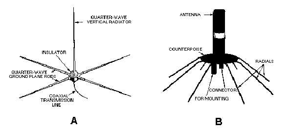
There are gazillions of antennas on tops of poles
that look like this:
[img]cid:7.1.0.9.0.20110126211625.01d97890(at)aeroelectric.com.0[/img]
None are even associated with the DC power system of the radio
at the other end of coax feed line.
But when, for example, a comm antenna is mounted on top of the wing on a Cessna, I presume it is electrically bonded to the wing which acts as the ground plane. But isn't the wing also part of the ground system for the airplane itself? With a coax connector attached to the antenna isn't there now two ground paths from the antenna to the radio chassis in its mounting rack? Does this create a ground loop and if so, are its effects positive, benign, or negative? Or is the ground through the coax between the antenna and the radio isolated in the radio chassis so the loop isn't completed? In thinking about my setup (if I had an-all metal airplane), it seems like the loop would be completed since the BNC connector at the radio end of the feed line connects to another BNC connector that is mounted in the back plane of the radio (Garmin 430W) chassis and it appears to me that the pass-through BNC connector in the chassis back plane isn't insulated from the radio chassis itself.
Your getting the investigation wrapped around
the axles of irrelevant data.
Get your ground plane bonding taken care of and
you're good to go.
Bob . . .
| | - The Matronics AeroElectric-List Email Forum - | | | Use the List Feature Navigator to browse the many List utilities available such as the Email Subscriptions page, Archive Search & Download, 7-Day Browse, Chat, FAQ, Photoshare, and much more:
http://www.matronics.com/Navigator?AeroElectric-List |
|
| Description: |
|
| Filesize: |
43.34 KB |
| Viewed: |
635 Time(s) |
|
|
|

