 |
Matronics Email Lists
Web Forum Interface to the Matronics Email Lists
|
| View previous topic :: View next topic |
| Author |
Message |
nuckolls.bob(at)aeroelect
Guest
|
 Posted: Sat Apr 07, 2012 7:41 pm Post subject: Next generation wig-wag controller for LED lamps Posted: Sat Apr 07, 2012 7:41 pm Post subject: Next generation wig-wag controller for LED lamps |
 |
|
At 01:20 PM 4/7/2012, you wrote:
| Quote: | --> AeroElectric-List message posted by: "gregmchugh" <gregmchugh(at)aol.com>
Bob,
Thanks for the info.
What is the limiting factor on power to the LED's?
I am planning to use the Teledyne LED lights that use 45 watts, so
about 4 amps at 12 volts for each light. What changes would be
needed to up the power capability by a factor of two. Different parts?
Different packaging? Different connector? Heatsinks? |
Heatsinks. Just because a device is RATED at xx
amps, doesn't mean that it will carry that current
waving around in breeze . . . unless it's a strong
breeze and maybe down around -40 or so. The parts
as shown are good for over 10A if the FETs are
thoughtfully accommodated with respect to getting
rid of their heat.
Actually, these fets might be okay at 5A with little
or no heatsinking . . . didn't bother to run the numbers.
But in any case, upsizing for the larger lamps is no big
deal.
| Quote: | What is the frequency of the wig-wag function and how is that set
by the components? |
The 1M/1uF network sets flash rate. That combination
with the 4093's I had in the bin gave about 340 mS
in one state and 450 mS in the others. One of the
characteristics of the cmos-gate astable is that
the hysteresis band is not centered between Vcc/Vdd,
hence the peg-leg gait of the flash pattern.
Of course, this wouldn't hurt the serviceability of
the device . . . in fact, folks would know who was
inbound from many miles out by the pattern of your
wig-wag.
The 'fix' would be to add a resistor and diode in
parallel with the 1M and adjust for better symmetry
-OR- change the oscillator to a 555 timer -OR- add
a divide by two flip-flop and double the frequency
of the oscillator.
The design goal was minimum parts count but with some
additional 'silicon herbs and spices' . . . the flavor
of the dish can be improved.
| Quote: | I am a software engineer so I know enough
about hardware design to be dangerous, but I am in the process
of learning more. |
Good for you! We all gotta start somewhere. My career
got officially launched in the basement of an uncle who
was big wig engineer for local power company. He taught
me the early motions of soldering things together . . .
with an iron that was the size of a billy club and took
20 minutes to warm up!
Hmmm . . . if you can herd the bytes around in a
microcontroller, there are some $1 devices from PIC that
would take care of your flash timer and push-pull outputs
to logic level gates on power fets. Of course, other
inputs could be used to control OFF/WW/ON functionality.
If you're interested in getting your feet wet in
etched circuit board layout, check out the free
CAD package from expresspcb.com
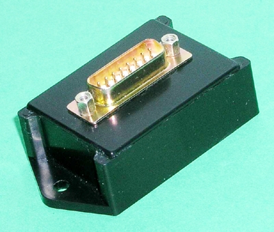
It might even be that the end-product can be fitted
into this stock enclosure
[img]cid:.0[/img]
There's a gazillion ways to do this. Let's pick one
that gets your juices going . . .
Bob . . .
| | - The Matronics AeroElectric-List Email Forum - | | | Use the List Feature Navigator to browse the many List utilities available such as the Email Subscriptions page, Archive Search & Download, 7-Day Browse, Chat, FAQ, Photoshare, and much more:
http://www.matronics.com/Navigator?AeroElectric-List |
|
| Description: |
|
| Filesize: |
109.43 KB |
| Viewed: |
6012 Time(s) |
|
|
|
| Back to top |
|
 |
gregmchugh
Joined: 03 Apr 2012
Posts: 42
|
| Posted: Sun Apr 08, 2012 9:47 am Post subject: Re: Next generation wig-wag controller for LED lamps |
|
|
Bob,


Thanks for the follow-up info.


I do like the idea of going with a micro to allow programmable

functions with a standard module/connector design.


What is the source for the d-sub enclosure you suggested?


How much current can be handled by a single pin on the connector?


Greg McHugh
| | - The Matronics AeroElectric-List Email Forum - | | | Use the List Feature Navigator to browse the many List utilities available such as the Email Subscriptions page, Archive Search & Download, 7-Day Browse, Chat, FAQ, Photoshare, and much more:
http://www.matronics.com/Navigator?AeroElectric-List |
|
|
|
| Back to top |
|
|
nuckolls.bob(at)aeroelect
Guest
|
| Posted: Sun Apr 08, 2012 2:12 pm Post subject: Next generation wig-wag controller for LED lamps |
|
|
At 12:47 PM 4/8/2012, you wrote:
--> AeroElectric-List message posted by: "gregmchugh" <gregmchugh(at)aol.com>
Bob,
Thanks for the follow-up info.
I do like the idea of going with a micro to allow programmable
functions with a standard module/connector design.
What is the source for the d-sub enclosure you suggested?
got a bucket full of them . . .
How much current can be handled by a single pin on the connector?
5A but I'd parallel up two pins for each power
path . . . there are plenty of extras. I qualified
this process on a military targets program about
15 years ago.
http://tinyurl.com/7h9h76r
for this power distribution controller
http://tinyurl.com/8x5rssq
for this target
http://tinyurl.com/6myc494
Works good, lasts a long time.
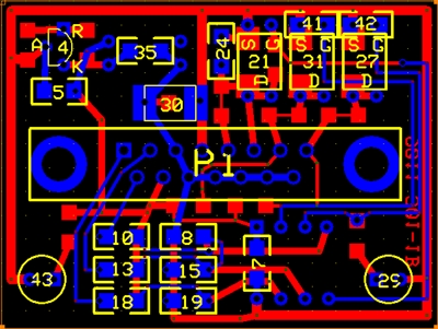
First gate to pass is to select logic level
FETs with sufficient current rating and make
sure you can get rid of the heat in this
2.8 x 1.4 footprint.
[img]cid:.0[/img]
Here's the schematic for this particular layout.
http://tinyurl.com/7m56z8o
Depending on what parts are put on, which are
left off, what the values are and what software
is in the uC, you can do a lot of different things
with it . . . and probably the next generation
wig wag.
You game to herd byes in a PIC RISC?
Bob . . .
| | - The Matronics AeroElectric-List Email Forum - | | | Use the List Feature Navigator to browse the many List utilities available such as the Email Subscriptions page, Archive Search & Download, 7-Day Browse, Chat, FAQ, Photoshare, and much more:
http://www.matronics.com/Navigator?AeroElectric-List |
|
| Description: |
|
| Filesize: |
130.09 KB |
| Viewed: |
5984 Time(s) |
|
|
|
| Back to top |
|
|
gregmchugh
Joined: 03 Apr 2012
Posts: 42
|
| Posted: Mon Apr 09, 2012 8:21 am Post subject: Re: Next generation wig-wag controller for LED lamps |
|
|
Bob,


I probably should have changed the Subject line on this but I decided to leave it alone to continue

the thread we had started. It is getting away from the LED wig-wag topic...


I have thought about this a little and I think it would be worthwhile to consider the option of a general purpose

programmable module and use the LED wig-wag as a simple example application. I see three useful

characteristics for this module:


1. Functionality set in software

2. Some capability to configure the I/O circuits for each application

3. A standard module package and connector such as the one you showed using an enclosed case with d-sub connector


To be useful for a wide audience there needs to be simple learning curve for developing the software

functionality and I/O configuration. I agree that the use of a PIC micro would be the way to go based on

their ready availability, good price per performance, and availability of development tools.


In order to make it attractive for general use I would propose the following:


Software Development - The learning curve for using the standard PIC software development tools

is pretty steep for a novice and I would expect many would shy away from that learning curve. There

are some third party development tools designed to ease the learning curve but at a price of $150 and up

they are not targeted at the novice hobbyist. An attractive option is the line of PICAXE micros targeted

at the education market and easily applied to the types of applications being considered here (I don't

think we are looking at applications that require high performance embedded processing). You can

get started with PICAXE development for $25 to $50 depending on which processor and which

downloading cable you use. The PICAXE development environment is free and easy to use for the

novice with the capability to simulate the micro operation without connection to a micro. The use

of a version of BASIC designed for embedded applications makes it easy to program but there

is an execution speed hit due to the use of a code interpreter in the PICAXE micro instead of using a compiler

to generate machine code for a plain PIC. Again, I don't see this execution speed penalty as a major issue for

most applications. As you gain experience you could make a switch to standard PIC micros and

use C or assembly language. The group behind PICAXE (Revolution Education in Britain) gets funds from

selling the PICAXE versions of the PIC micro (preloaded with the program loader and interpreter) and

development boards/kits. Here is a link to the free software development environment:


http://www.picaxe.com/Software/PICAXE/PICAXE-Programming-Editor


You can find more PICAXE info at (including lots of examples and tutorials):


http://www.picaxe.com/


and there are three U.S. distributers:


http://www.sparkfun.com/categories/125


http://www.robotshop.com/search/search.aspx?locale=en_us&keywords=picaxe


http://www.phanderson.com/picaxe/


I/O Configuration - In parallel with a need for easy software development I see a need for easy configuration

of I/O interfaces to the devices outside the module. There a plenty of examples and tutorials for interfacing

the PICAXE to all types of devices and here are some examples of general purpose modules that allow

I/O configuration (usually through the provision of a prototyping area on the module):


From VX-Aviation, the Proton-225 board based on a PIC micro with a prototyping area and a package

using standard d-sub 25 pin connectors and housing which is compatible with the other products they provide. You can download a pdf description here:


http://www.vx-aviation.com/docs.html


From PICAXE there are several standard development boards that include the provision for varying levels of I/O configuration:


http://www.picaxe.com/Hardware/Project-Boards/PICAXE-08-Proto-Board/


http://www.picaxe.com/Hardware/Project-Boards/PICAXE-14-Project-Board/


http://www.picaxe.com/Hardware/Project-Boards/PICAXE-18-Project-Board/


I don't know enough about hardware design to know if the use of these types of boards or even just a prototyping board

from Radio Shack are robust enough to handle the environment of mounting in an experimental aircraft but based on the

VX-Aviation module it would seem they may be up to the job...


Anyway, this note is getting a little long so I will end it here. I would appreciate feedback from anyone who is interested

in something along these lines in order to see if my thoughts on this make any sense to anyone beside me. I am only

interested as an end user of the module and have no real interest in designing / producing any type of hardware boards.

I can handle setting up the I/O circuits on a pre-made board but I don't have much interest in board development even

though I know it is something that is not that hard to learn. Just a matter of only so many things that you can do, even

when you are retired from a "real" job. I have read and studied the AeroElectric Connection book and have a draft

design for the electrical system on the Sonex Xenos motor glider that I am building. But as I pointed out in a previous note,

like most software engineers, I know just enough about hardware design to be dangerous...


Greg McHugh
| | - The Matronics AeroElectric-List Email Forum - | | | Use the List Feature Navigator to browse the many List utilities available such as the Email Subscriptions page, Archive Search & Download, 7-Day Browse, Chat, FAQ, Photoshare, and much more:
http://www.matronics.com/Navigator?AeroElectric-List |
|
|
|
| Back to top |
|
|
nuckolls.bob(at)aeroelect
Guest
|
| Posted: Tue Apr 10, 2012 3:38 pm Post subject: Next generation wig-wag controller for LED lamps |
|
|
At 11:57 AM 4/9/2012, you wrote:
| Quote: |
To that goal, I'd like to suggest using an Arduino.
|
This is a highly capable device but a bit of an
overkill for things like wig-wag flashers, voltage
monitors, etc.
The challenge is to exploit the scope of
projects that can be implemented in a user
friendly package of the smallest practical
size, cost and parts count. An already stuffed
Arduino board has no aviation friendly i/o
or even an enclosure for $30. I would expect
the wig-wag flasher to be drop-in ready for
use on an airplane and have total bill of
materials under $20 or so.
Bob . . .
| | - The Matronics AeroElectric-List Email Forum - | | | Use the List Feature Navigator to browse the many List utilities available such as the Email Subscriptions page, Archive Search & Download, 7-Day Browse, Chat, FAQ, Photoshare, and much more:
http://www.matronics.com/Navigator?AeroElectric-List |
|
|
|
| Back to top |
|
|
fvfdums
Joined: 13 Dec 2019
Posts: 1
|
| Posted: Sun Dec 15, 2019 7:48 pm Post subject: Re: Next generation wig-wag controller for LED lamps |
|
|
oh,it is a good idea.Good ideas are just for everyone to share.


--------------------------------------------------------------------


My stepper motor website:skysmotor.com - Machinery Design ? - ? Stepper Moter Development


"Necessity is the mother of invention." - Author unknown.
| | - The Matronics AeroElectric-List Email Forum - | | | Use the List Feature Navigator to browse the many List utilities available such as the Email Subscriptions page, Archive Search & Download, 7-Day Browse, Chat, FAQ, Photoshare, and much more:
http://www.matronics.com/Navigator?AeroElectric-List |
|
|
|
| Back to top |
|
|
nuckolls.bob(at)aeroelect
Guest
|
| Posted: Mon Dec 16, 2019 8:16 am Post subject: Next generation wig-wag controller for LED lamps |
|
|
At 09:48 PM 12/15/2019, you wrote:
| Quote: | --> AeroElectric-List message posted by: "fvfdums" <kakaxiu9(at)gmail.com>
oh,it is a good idea.Good ideas are just for everyone to share.
--------------------------------------------------------------------
My stepper motor website:skysmotor.com ( https://www.skysmotor.com/) - Machinery Design ? - ? Stepper Moter Development
"Necessity is the mother of invention." - Author unknown. |
INTERLOPER . . . IGNORE
Bob . . .
| | - The Matronics AeroElectric-List Email Forum - | | | Use the List Feature Navigator to browse the many List utilities available such as the Email Subscriptions page, Archive Search & Download, 7-Day Browse, Chat, FAQ, Photoshare, and much more:
http://www.matronics.com/Navigator?AeroElectric-List |
|
|
|
| Back to top |
|
|
|
|
You cannot post new topics in this forum
You cannot reply to topics in this forum
You cannot edit your posts in this forum
You cannot delete your posts in this forum
You cannot vote in polls in this forum
You cannot attach files in this forum
You can download files in this forum
|
Powered by phpBB © 2001, 2005 phpBB Group
|

