 |
Matronics Email Lists
Web Forum Interface to the Matronics Email Lists
|
| View previous topic :: View next topic |
| Author |
Message |
nuckolls.bob(at)aeroelect
Guest
|
 Posted: Tue Aug 25, 2009 8:11 am Post subject: Dan's Jabiru 3300 Wiring Schematic Posted: Tue Aug 25, 2009 8:11 am Post subject: Dan's Jabiru 3300 Wiring Schematic |
 |
|
| Quote: |
Although the manual lists the magneto kill switch as a possible tach
signal source, any fault in the signal wire would short out the
magneto. Who knows what affect the 10K ohm impedance of the RDAC VD
would have on the ignition system? Since the dynamo is integrated
with the flywheel and generates AC voltage, it should provide the
RPM signal. It is worth a try.
|
Resistances as low as a few hundred ohms will probably
have no effect on ignition performance . . . the kill
switch on magneto-type ignition systems generally places
a dead short on a few turns of the spark voltage coil
thus killing it's ability to function. This is a rather
low impedance energy source and not easily "loaded"
to the extent that the ignition fails. The biggest
problem with getting tach data from ignition sources
is the very trashy waveform that CAN be easily signal
conditioned if the tach designer is aware of the
signal's characteristics.
| Quote: | Bob said:
> You show a tach signal off the AC widings of the altenrator.
> This will not be useful with the alternator disconnect relay
> open.
Bob, I do not understand this, since the tach signal wire is
connected to the alternator side of the disconnect relay. Doesn't
the alternator continue to generator voltage whether there is a load
on it or not? Or does the regulator open the grounded alternator lead?
|
The alternator leads go to a bridge rectifier's AC
input poles . . . neither goes to ground.
Availability of a predictable signal from the
AC windings assumes that the system is producing
power normally. Now, there is SOME sort of signal
present with the relay open . . . but its characteristics
are different that for normal operation. The
designer of the tachometer probably wasn't tasked
with covering this case so useful operation becomes
problematic.
Bob . . .
---------------------------------------
( . . . a long habit of not thinking )
( a thing wrong, gives it a superficial )
( appearance of being right . . . )
( )
( -Thomas Paine 1776- )
---------------------------------------
| | - The Matronics AeroElectric-List Email Forum - | | | Use the List Feature Navigator to browse the many List utilities available such as the Email Subscriptions page, Archive Search & Download, 7-Day Browse, Chat, FAQ, Photoshare, and much more:
http://www.matronics.com/Navigator?AeroElectric-List |
|
|
|
| Back to top |
|
 |
messydeer
Joined: 13 Feb 2006
Posts: 214
Location: Bellingham, WA
|
| Posted: Tue Aug 25, 2009 8:27 am Post subject: Re: Dan's Jabiru 3300 Wiring Schematic |
|
|
Thanks, Joe 
I'd heard of getting a tach signal from the P-leads. This must be the same as what they talk about with the mags. And would have the same risks of grounding, I would think.
| Quote: | You show a tach signal off the AC widings of the altenrator.
This will not be useful with the alternator disconnect relay
open. |
Here's my understanding: the alternator has two leads of AC coming out. With AC, one lead will have current go out, while the other has it come in (like a ground?). The leads switch every 180. So opening just one of the leads kills output, just like breaking a ground connection in a DC circuit.
It also seems that if I did get the tach signal here, then I would have a defacto open alternator disconnect relay alarm: no tach would mean relay open.
| | - The Matronics AeroElectric-List Email Forum - | | | Use the List Feature Navigator to browse the many List utilities available such as the Email Subscriptions page, Archive Search & Download, 7-Day Browse, Chat, FAQ, Photoshare, and much more:
http://www.matronics.com/Navigator?AeroElectric-List |
|
_________________
Dan |
|
| Back to top |
|
|
user9253
Joined: 28 Mar 2008
Posts: 1967
Location: Riley TWP Michigan
|
| Posted: Thu Aug 27, 2009 6:46 pm Post subject: Re: Dan's Jabiru 3300 Wiring Schematic |
|
|
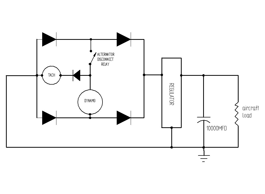
I have taken a portion of Dan's schematic that pertains to the dynamo, regulator, and tachometer and simplified it in an attempt to better understand it.  I moved the bridge rectifier outside of the regulator.  And I added one more diode in series with the tach so that the tach only sees half of the dynamo waveform.  By adding this extra diode, I believe that the tach will see the same signal whether the alternator relay is pulled in or not, since the tach is connected in parallel with the dynamo through two diodes.  The dynamo frequency is dependent upon the engine speed since it is mounted onto the flywheel.  The output voltage will vary depending of the state of the disconnect relay and aircraft load.  However, the voltage should not affect the tach unless it drops below the minimum (2.5 to 5 volts) required.

   Bob, what do you think?  Will Dan's tach work as connected in his schematic if a diode is added in series with it?  Or do I have it all wrong?  And that could be, because I do not know what is inside of the regulator case.

Joe
| | - The Matronics AeroElectric-List Email Forum - | | | Use the List Feature Navigator to browse the many List utilities available such as the Email Subscriptions page, Archive Search & Download, 7-Day Browse, Chat, FAQ, Photoshare, and much more:
http://www.matronics.com/Navigator?AeroElectric-List |
|
| Description: |
|
| Filesize: |
47.82 KB |
| Viewed: |
5419 Time(s) |
|
_________________
Joe Gores |
|
| Back to top |
|
|
nuckolls.bob(at)aeroelect
Guest
|
| Posted: Fri Aug 28, 2009 6:54 am Post subject: Dan's Jabiru 3300 Wiring Schematic |
|
|
At 09:46 PM 8/27/2009, you wrote:
| Quote: |
I have taken a portion of Dan's schematic that pertains to the
dynamo, regulator, and tachometer and simplified it in an attempt to
better understand it. I moved the bridge rectifier outside of the
regulator. And I added one more diode in series with the tach so
that the tach only sees half of the dynamo waveform. By adding this
extra diode, I believe that the tach will see the same signal
whether the alternator relay is pulled in or not, since the tach is
connected in parallel with the dynamo through two diodes. The
dynamo frequency is dependent upon the engine speed since it is
mounted onto the flywheel. The output voltage will vary depending
of the state of the disconnect relay and aircraft load. However,
the voltage should not affect the tach unless it drops below the
minimum (2.5 to 5 volts) required.
Bob, what do you think? Will Dan's tach work as connected in
his schematic if a diode is added in series with it? Or do I have
it all wrong? And that could be, because I do not know what is
inside of the regulator case.
|
Good question. You know what you do not know.
Similarly, I know that I know nothing about
the functional requirements for any particular
tachometer. It's unwise for me to suggest that
modification of the tachometer's signal path (by
breaking one AC lead from the alternator) will
not have a deleterious effect on its performance.
You're on the right track for the crafting an
experiment and verifying the significance of
results before you fly the airplane. But the
"2.5 to 5.0 volts minimum" requirement does
not speak to distortions of waveform.
I'm in CA right now sorting out the simple-ideas
for the outcome of an experiment that was not conducted
to a useful and significant conclusion before
flight.
The short answer to your question is hook it
up, give it a try. It wouldn't hurt to take some
'scope waveform data on the relay-open and
relay-closed conditions. Then share those pictures
with the the folks who built the tach. It's
a sure bet that they did not anticipate a need
to remain functional with one of the AC power
leads from the dynamo disconnected from the
rectifier/regulator.
Bob . . .
---------------------------------------
( . . . a long habit of not thinking )
( a thing wrong, gives it a superficial )
( appearance of being right . . . )
( )
( -Thomas Paine 1776- )
---------------------------------------
| | - The Matronics AeroElectric-List Email Forum - | | | Use the List Feature Navigator to browse the many List utilities available such as the Email Subscriptions page, Archive Search & Download, 7-Day Browse, Chat, FAQ, Photoshare, and much more:
http://www.matronics.com/Navigator?AeroElectric-List |
|
|
|
| Back to top |
|
|
user9253
Joined: 28 Mar 2008
Posts: 1967
Location: Riley TWP Michigan
|
| Posted: Fri Aug 28, 2009 8:59 am Post subject: Re: Dan's Jabiru 3300 Wiring Schematic |
|
|
Thanks for the reply Bob.  Unfortunately I live a long way from Dan.  Perhaps he will let us know how he connected his tachometer to make it work to his satisfaction.

Joe
| | - The Matronics AeroElectric-List Email Forum - | | | Use the List Feature Navigator to browse the many List utilities available such as the Email Subscriptions page, Archive Search & Download, 7-Day Browse, Chat, FAQ, Photoshare, and much more:
http://www.matronics.com/Navigator?AeroElectric-List |
|
_________________
Joe Gores |
|
| Back to top |
|
|
|
|
You cannot post new topics in this forum
You cannot reply to topics in this forum
You cannot edit your posts in this forum
You cannot delete your posts in this forum
You cannot vote in polls in this forum
You cannot attach files in this forum
You can download files in this forum
|
Powered by phpBB © 2001, 2005 phpBB Group
|

