 |
Matronics Email Lists
Web Forum Interface to the Matronics Email Lists
|
| View previous topic :: View next topic |
| Author |
Message |
messydeer
Joined: 13 Feb 2006
Posts: 214
Location: Bellingham, WA
|
 Posted: Fri Nov 20, 2009 3:09 pm Post subject: Dan's Switches Posted: Fri Nov 20, 2009 3:09 pm Post subject: Dan's Switches |
 |
|
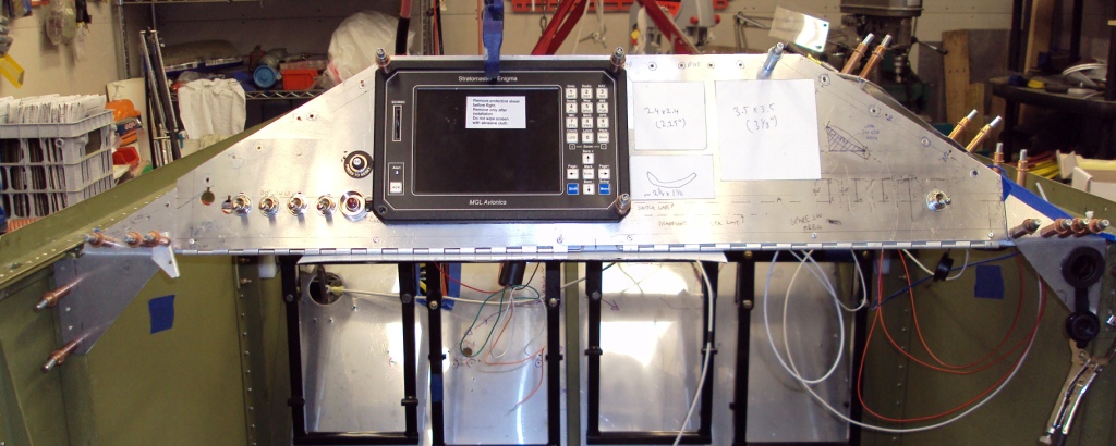
Hello!


I've done a fair amount of crimping and a little soldering while wiring my instrument panel mockup,  and have a few questions. Maybe posting one or two pics per post will work. This is for my Jabiru 3300 Sonex with a standard ~30 degree tilted panel. I've put a piano hinge along the bottom and top with a few nutplates to go on the side. The tank and glareshield are removed. Tank has roughly the same cross section as the panel face, starts about a foot in front of the panel to the firewall.
| | - The Matronics AeroElectric-List Email Forum - | | | Use the List Feature Navigator to browse the many List utilities available such as the Email Subscriptions page, Archive Search & Download, 7-Day Browse, Chat, FAQ, Photoshare, and much more:
http://www.matronics.com/Navigator?AeroElectric-List |
|
| Description: |
|
| Filesize: |
199.59 KB |
| Viewed: |
18687 Time(s) |
|
_________________
Dan |
|
| Back to top |
|
 |
messydeer
Joined: 13 Feb 2006
Posts: 214
Location: Bellingham, WA
|
| Posted: Fri Nov 20, 2009 3:17 pm Post subject: Re: Dan's Switches |
|
|
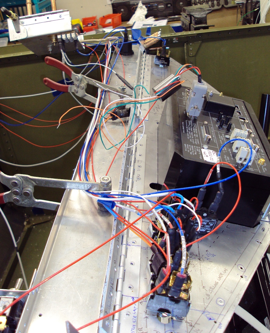
This pic is from the left side looking right, with the panel tilted forward. Some have had interference problems with the top of the Enigma hitting the glare shield, but mine just fits.


At the top of the pic you can see the cover for the main buss. It's mocked up to fit on the underside of the glare shield. Taking out the top hinge pin will let it swing down for easier access. On the bottom side of the cover I've mounted a section of ground tabs.
| | - The Matronics AeroElectric-List Email Forum - | | | Use the List Feature Navigator to browse the many List utilities available such as the Email Subscriptions page, Archive Search & Download, 7-Day Browse, Chat, FAQ, Photoshare, and much more:
http://www.matronics.com/Navigator?AeroElectric-List |
|
| Description: |
|
| Filesize: |
473.96 KB |
| Viewed: |
18684 Time(s) |
|
_________________
Dan |
|
| Back to top |
|
|
messydeer
Joined: 13 Feb 2006
Posts: 214
Location: Bellingham, WA
|
| Posted: Fri Nov 20, 2009 3:26 pm Post subject: Re: Dan's Switches |
|
|
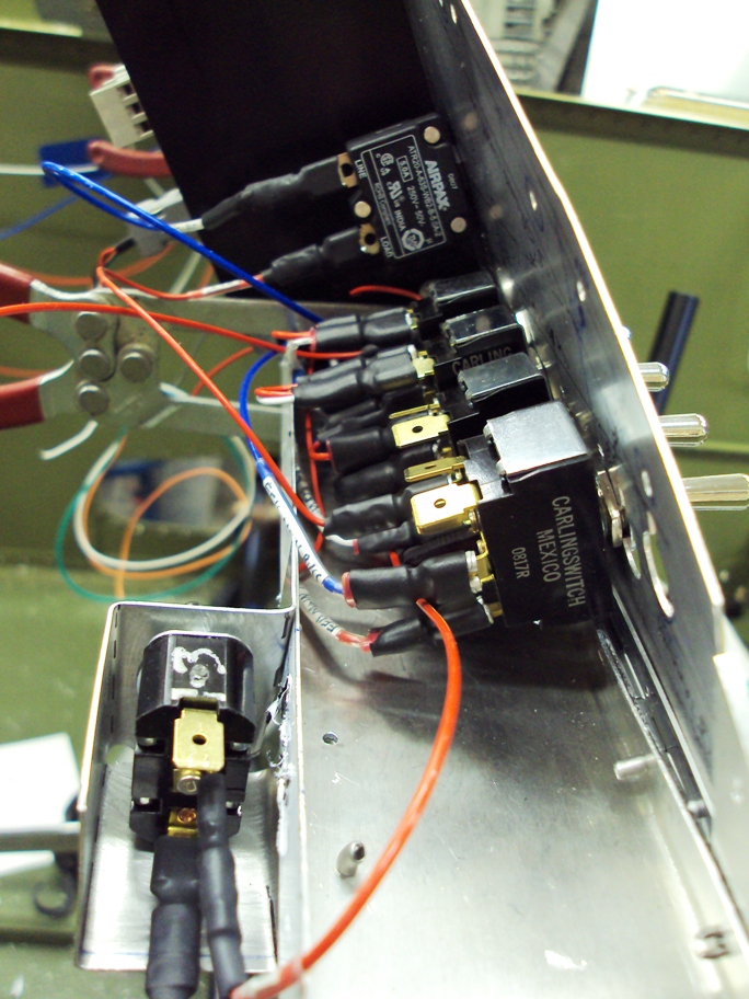
This is with the panel in the closed position. The channel that the lower piano hinge attaches to is 025 with either 1/2" or 3/4" flanges. Some of the  longer wires, like the blue one in the foreground, can be tucked away from the flange. There are a few shorter wires that need to have a zip tie pull them up and away, or maybe ben up the switch terminals. The 3rd switch back is a good example. It has a white and red wire resting on the flange.


In the foreground is my security switch for the starter button, mentioned in earlier posts.
| | - The Matronics AeroElectric-List Email Forum - | | | Use the List Feature Navigator to browse the many List utilities available such as the Email Subscriptions page, Archive Search & Download, 7-Day Browse, Chat, FAQ, Photoshare, and much more:
http://www.matronics.com/Navigator?AeroElectric-List |
|
| Description: |
|
| Filesize: |
344.42 KB |
| Viewed: |
18681 Time(s) |
|
_________________
Dan |
|
| Back to top |
|
|
messydeer
Joined: 13 Feb 2006
Posts: 214
Location: Bellingham, WA
|
| Posted: Fri Nov 20, 2009 3:32 pm Post subject: Re: Dan's Switches |
|
|
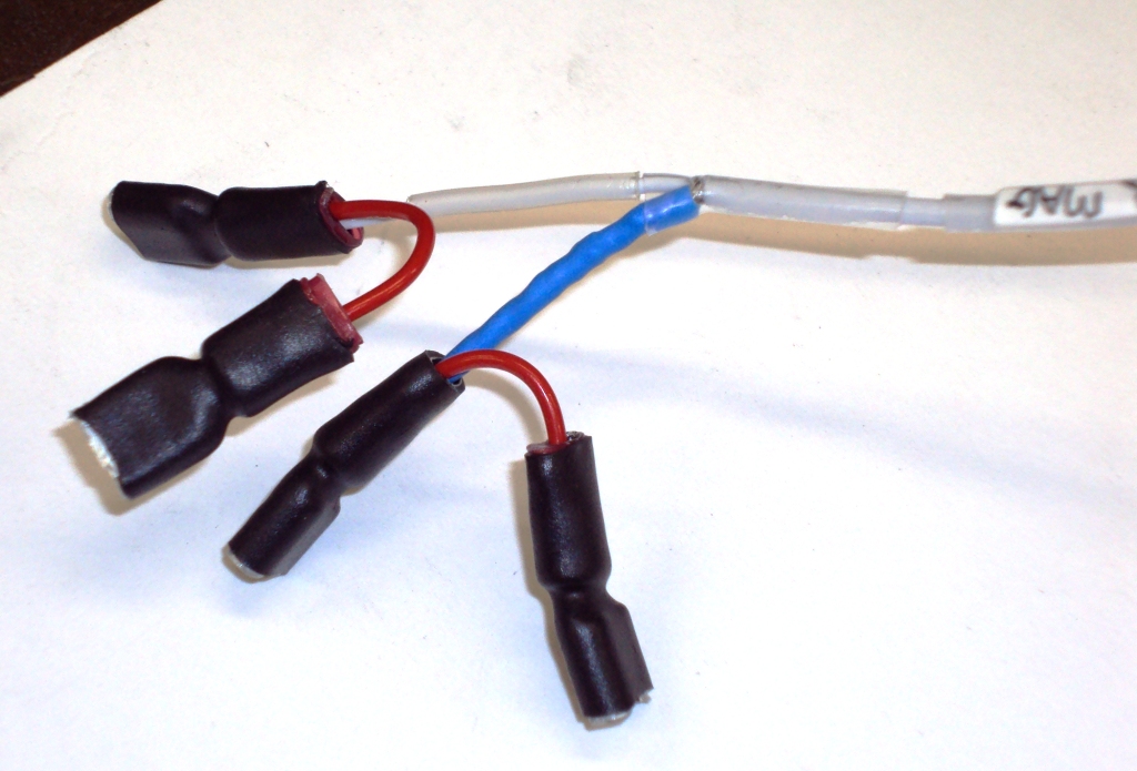
Since a DPDT switch is the same size and almost the same price as a SPST, I thought I could increase switch reliability by putting in 2-3 instead of 1-3 switches. The pic shows one for a magneto lead. I separated the shield and put blue heatshrink on the braid and covered the junction with a piece of clear heatshrink.
| | - The Matronics AeroElectric-List Email Forum - | | | Use the List Feature Navigator to browse the many List utilities available such as the Email Subscriptions page, Archive Search & Download, 7-Day Browse, Chat, FAQ, Photoshare, and much more:
http://www.matronics.com/Navigator?AeroElectric-List |
|
| Description: |
|
| Filesize: |
378.26 KB |
| Viewed: |
18678 Time(s) |
|
_________________
Dan |
|
| Back to top |
|
|
messydeer
Joined: 13 Feb 2006
Posts: 214
Location: Bellingham, WA
|
| Posted: Fri Nov 20, 2009 3:47 pm Post subject: Re: Dan's Switches |
|
|
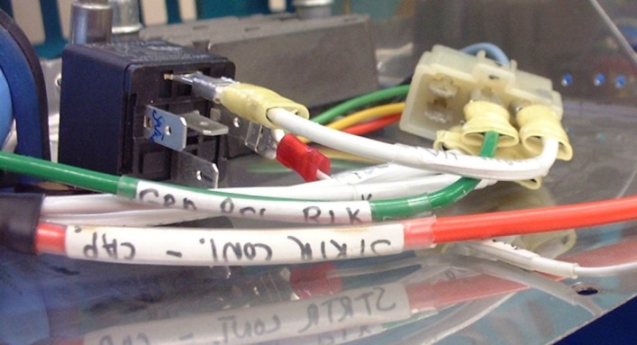
Last week I crimped connections betwen my regulator and alternator relay. The Jabiru regulator comes with a harness or whatever you call the plastic thing with 6 male faston blades inside. Besides being a bit cramped in there, one of the blades is a bit loose. I think it just got pushed or pulled out of its socket, since I can't budge the female-male faston connection. For this reason I'm thinking of cutting off the plastic harness (and tabs, if needed) to free up the individual wires.


I also realize the fastons to the relay aren't in all the way. And it needs a diode.
| | - The Matronics AeroElectric-List Email Forum - | | | Use the List Feature Navigator to browse the many List utilities available such as the Email Subscriptions page, Archive Search & Download, 7-Day Browse, Chat, FAQ, Photoshare, and much more:
http://www.matronics.com/Navigator?AeroElectric-List |
|
| Description: |
|
| Filesize: |
67.35 KB |
| Viewed: |
18673 Time(s) |
|
_________________
Dan |
|
| Back to top |
|
|
user9253
Joined: 28 Mar 2008
Posts: 1967
Location: Riley TWP Michigan
|
|
| Back to top |
|
|
nuckolls.bob(at)aeroelect
Guest
|
| Posted: Sat Nov 21, 2009 6:02 am Post subject: Dan's Switches |
|
|
At 05:32 PM 11/20/2009, you wrote:
| Quote: |
Since a DPDT switch is the same size and almost the same price as a
SPST, I thought I could increase switch reliability by putting in
2-3 instead of 1-3 switches.
|
But if one half of the switch fails, how will you
know it? Don't confuse reliability with longevity.
Reliability for your flight system (of which YOU
are a component) is achieved by a combination of
understanding, skill, failure tolerant design
and preventative maintenance that takes up the
slack for issues of longevity/service-life.
Bob . . .
---------------------------------------
( It's MATRONICS FUND RAISER MONTH! )
( Do your part to keep this marvelous )
( tool sharp and available to all our )
( brothers in the OBAM aviation )
( community. )
---------------------------------------
| | - The Matronics AeroElectric-List Email Forum - | | | Use the List Feature Navigator to browse the many List utilities available such as the Email Subscriptions page, Archive Search & Download, 7-Day Browse, Chat, FAQ, Photoshare, and much more:
http://www.matronics.com/Navigator?AeroElectric-List |
|
|
|
| Back to top |
|
|
user9253
Joined: 28 Mar 2008
Posts: 1967
Location: Riley TWP Michigan
|
| Posted: Sat Nov 21, 2009 6:14 am Post subject: Re: Dan's Switches |
|
|
Dan,
I do have one suggestion about the regulator_fastons_118.jpg. Unless it will be necessary to periodically disconnect the cable going to the regulator, you could eliminate that plastic connector and the fastons. One of the regulator wires could go directly to the relay. The other wires could be butt spliced like this: | Code: | | http://www.aeroelectric.com/articles/PM_Solder_Sleeve/PM_Solder_Sleeve.html |
Joe
| | - The Matronics AeroElectric-List Email Forum - | | | Use the List Feature Navigator to browse the many List utilities available such as the Email Subscriptions page, Archive Search & Download, 7-Day Browse, Chat, FAQ, Photoshare, and much more:
http://www.matronics.com/Navigator?AeroElectric-List |
|
_________________
Joe Gores |
|
| Back to top |
|
|
dave.gribble(at)mchsi.com
Guest
|
| Posted: Sat Nov 21, 2009 7:25 am Post subject: Dan's Switches |
|
|
Dan - your pictures and wiring look great, congrats!
It looks like you are putting black heatshrink tubing on top of the insulated faston terminals. Is that for additional strain relief?
dave
-------------- Original message ----------------------
From: "user9253" <fran5sew(at)banyanol.com>
| Quote: |
Dan,
I do have one suggestion about the regulator_fastons_118.jpg. Unless it will be
|
necessary to periodically disconnect the cable going to the regulator, you could
eliminate that plastic connector and the fastons. One of the regulator wires
could go directly to the relay. The other wires could be butt spliced like
this:http://www.aeroelectric.com/articles/PM_Solder_Sleeve/PM_Solder_Sleeve.
| | - The Matronics AeroElectric-List Email Forum - | | | Use the List Feature Navigator to browse the many List utilities available such as the Email Subscriptions page, Archive Search & Download, 7-Day Browse, Chat, FAQ, Photoshare, and much more:
http://www.matronics.com/Navigator?AeroElectric-List |
|
|
|
| Back to top |
|
|
user9253
Joined: 28 Mar 2008
Posts: 1967
Location: Riley TWP Michigan
|
| Posted: Sat Nov 21, 2009 8:18 am Post subject: Re: Dan's Switches |
|
|
With a Double Pole switch wired in parallel, one will not know when one half fails because the circuit will still operate with only half of the switch working.  If at some point the second half of the switch fails, then the pilot will not be any worse off then if a single-pole switch had failed.  Theoretically a DP switch wired in parallel will last longer than a SP switch because each half only carries half of the current.  As corrosion forms, the resistance of contacts in parallel will be half.  Has anyone, perhaps a switch manufacturer, done experiments to determine the longevity of a DP switch wired in parallel compared to a SP switch?  It is easier to install a longer-lived switch during panel build while the circuit is fresh in mind, and while the components are easily accessible.  Is it worth the extra cost and weight and time to install a double pole switch in an attempt to delay future trouble shooting and difficult replacing of switches?

Joe
| | - The Matronics AeroElectric-List Email Forum - | | | Use the List Feature Navigator to browse the many List utilities available such as the Email Subscriptions page, Archive Search & Download, 7-Day Browse, Chat, FAQ, Photoshare, and much more:
http://www.matronics.com/Navigator?AeroElectric-List |
|
_________________
Joe Gores |
|
| Back to top |
|
|
messydeer
Joined: 13 Feb 2006
Posts: 214
Location: Bellingham, WA
|
| Posted: Sat Nov 21, 2009 8:31 am Post subject: Re: Dan's Switches |
|
|
Good points, Bob and Joe.
Another issue is what route to take and how to fasten the wire bundle going from the firewall to the channel behind the instrument panel. Many have used the zip tie bases and simply glued them on. But I would like to see if I could do without glue that might let loose sometime in the future, especially in such a hard to reach place.
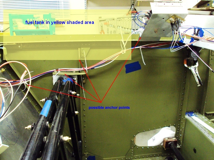
From my firewall bulkhead fitting to the side panel is about 12". This fitting is just out of view on the left of the pic. I would use the same zip tie anchors but fasten them with SS rivets through the firewall. 2 or 3 should do with zip ties also spaced between the anchors.
Then, instead of the side panel, I could use the 1/8" angle to support the anchors or clamps shown in the first 3 arrows in the pic. There would only be 3 or 4 inches between the anchors. After the upright angle I could go 8" to the bottom of the cover for the buss box, or follow the fat wire through the box itself, since there'd be room . The buss box cover will be fastened to the underside of the glare shield 2 or 3 inches behind the tank. Then the bundle would go another 4" and drop into the instrument panel tray.
I had shied away from using the upper longeron as support, but now I think that may be a better route. Instead of going to the buss box, I could simply rivet angle clips every 3 or 4 inches along the longeron to the panel tray. I could use either zip tie bases riveted to these clips, or use Adel clamps.
How does this sound?
| | - The Matronics AeroElectric-List Email Forum - | | | Use the List Feature Navigator to browse the many List utilities available such as the Email Subscriptions page, Archive Search & Download, 7-Day Browse, Chat, FAQ, Photoshare, and much more:
http://www.matronics.com/Navigator?AeroElectric-List |
|
| Description: |
|
| Filesize: |
197.04 KB |
| Viewed: |
18583 Time(s) |
|
_________________
Dan |
|
| Back to top |
|
|
messydeer
Joined: 13 Feb 2006
Posts: 214
Location: Bellingham, WA
|
| Posted: Sat Nov 21, 2009 8:44 am Post subject: Re: Dan's Switches |
|
|
| Quote: | | It looks like you are putting black heatshrink tubing on top of the insulated faston terminals. Is that for additional strain relief? |
The AMP PIDG terminals I got have the non-terminal end insulated only. Then when I first started crimping, it looked like some of the plastic could have been poked through. To be safe, I figured I'd best put on heatshrink, which could also be extended to cover the whole terminal. In some areas it also helps as a strain relief. Other areas I actually had to cutoff some of the heatshrink because this prevented it from bending as tight as I needed, like behind the switches. And putting on the heatshrink is pretty fast and fun, too!
| | - The Matronics AeroElectric-List Email Forum - | | | Use the List Feature Navigator to browse the many List utilities available such as the Email Subscriptions page, Archive Search & Download, 7-Day Browse, Chat, FAQ, Photoshare, and much more:
http://www.matronics.com/Navigator?AeroElectric-List |
|
_________________
Dan |
|
| Back to top |
|
|
user9253
Joined: 28 Mar 2008
Posts: 1967
Location: Riley TWP Michigan
|
| Posted: Sat Nov 21, 2009 9:21 am Post subject: Re: Dan's Switches |
|
|
Brian Carpenter from Rainbow Aviation, an A&P who teaches the E-LSA course, taught our class that wire ties should not be used to support wires.  Their purpose is only to keep wires in a neat bundle.  Adel clamps or other means should be used for support.  At work in an industrial environment, I have seen many of those sticky wire-tie bases fall off after a period of time.

Joe
| | - The Matronics AeroElectric-List Email Forum - | | | Use the List Feature Navigator to browse the many List utilities available such as the Email Subscriptions page, Archive Search & Download, 7-Day Browse, Chat, FAQ, Photoshare, and much more:
http://www.matronics.com/Navigator?AeroElectric-List |
|
_________________
Joe Gores |
|
| Back to top |
|
|
messydeer
Joined: 13 Feb 2006
Posts: 214
Location: Bellingham, WA
|
| Posted: Sat Nov 21, 2009 10:17 am Post subject: Re: Dan's Switches |
|
|
| Quote: | | wire ties should not be used to support wires |
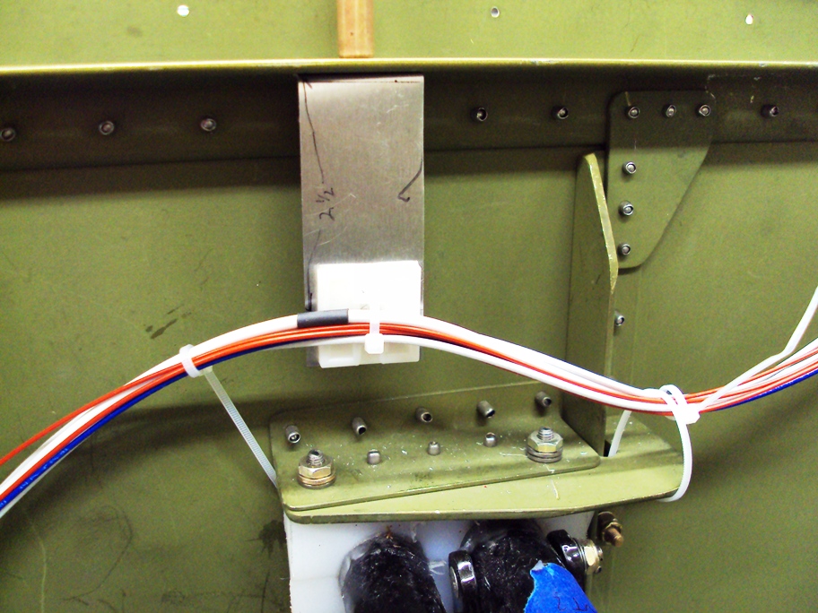
Seems to me a zip tie fastened to a tie base could fail where the base attaches to the structure, the two little plastic rods of the base where the tie slips under, or the zip tie itself. I think doing what I did in the pic below remedies the base to structure problem. I just bent a piece of 025 and riveted through the hole in the middle of the base. That's not gonna come off. In this particular shot, I made the angle clip 2.5" to the rivet. I could shorten that to 1", but 2.5" gives it more room between the clip and tank, since the sides of the tank angle down and toward the center. So if I had to service this item, it wouldn't be too hard...as long as I could still do a Fosbury Flop under the tank!
So the question is, could the zip tie or little base rod break? If so, I'd opt for the metal clamp. I suppose I'd still want the angle clip to give me clearance. Just replace the plastic base and tie with an Adel clamp.... and pray I don't ever have to mess with the dang screws later!
| | - The Matronics AeroElectric-List Email Forum - | | | Use the List Feature Navigator to browse the many List utilities available such as the Email Subscriptions page, Archive Search & Download, 7-Day Browse, Chat, FAQ, Photoshare, and much more:
http://www.matronics.com/Navigator?AeroElectric-List |
|
| Description: |
|
| Filesize: |
312.59 KB |
| Viewed: |
18563 Time(s) |
|
_________________
Dan |
|
| Back to top |
|
|
nuckolls.bob(at)aeroelect
Guest
|
| Posted: Sat Nov 21, 2009 10:54 am Post subject: Dan's Switches |
|
|
At 10:31 AM 11/21/2009, you wrote:
| Quote: |
Good points, Bob and Joe.
Another issue is what route to take and how to fasten the wire
bundle going from the firewall to the channel behind the instrument
panel. Many have used the zip tie bases and simply glued them on.
But I would like to see if I could do without glue that might let
loose sometime in the future, especially in such a hard to reach place.
|
There ARE bond-studs that can be used to attach non-structural
components to the airframe without drilling holes.
See:
http://www.aeroelectric.com/articles/Bond_Studs.pdf
There are aerospace grade, fast-setting bond studs
too . . . but you don't even want to know what they
cost.
| Quote: | >From my firewall bulkhead fitting to the side panel is about 12".
This fitting is just out of view on the left of the pic. I would
use the same zip tie anchors but fasten them with SS rivets through
the firewall. 2 or 3 should do with zip ties also spaced between the anchors.
|
Tie-straps and their companion stick-on/screw-on
bases are problematic. Likelihood of finding stuff
in your local hardware store suited to your task
is low.
| Quote: | Then, instead of the side panel, I could use the 1/8" angle to
support the anchors or clamps shown in the first 3 arrows in the
pic. There would only be 3 or 4 inches between the anchors. After
the upright angle I could go 8" to the bottom of the cover for the
buss box, or follow the fat wire through the box itself, since
there'd be room . The buss box cover will be fastened to the
underside of the glare shield 2 or 3 inches behind the tank. Then
the bundle would go another 4" and drop into the instrument panel tray.
I had shied away from using the upper longeron as support, but now I
think that may be a better route. Instead of going to the buss box,
I could simply rivet angle clips every 3 or 4 inches along the
longeron to the panel tray. I could use either zip tie bases riveted
to these clips, or use Adel clamps.
|
Adel (or MS21919DG series) clamps are almost NEVER a poor
choice. All metallic fastening is also almost NEVER a poor
choice. Any process involving plastics or stick-ums can
be a good choice but stick with proven recipes for success
for both ingredients and process.
Bob . . .
---------------------------------------
( It's MATRONICS FUND RAISER MONTH! )
( Do your part to keep this marvelous )
( tool sharp and available to all our )
( brothers in the OBAM aviation )
( community. )
---------------------------------------
| | - The Matronics AeroElectric-List Email Forum - | | | Use the List Feature Navigator to browse the many List utilities available such as the Email Subscriptions page, Archive Search & Download, 7-Day Browse, Chat, FAQ, Photoshare, and much more:
http://www.matronics.com/Navigator?AeroElectric-List |
|
|
|
| Back to top |
|
|
nuckolls.bob(at)aeroelect
Guest
|
| Posted: Sat Nov 21, 2009 10:57 am Post subject: Dan's Switches |
|
|
At 10:44 AM 11/21/2009, you wrote:
| Quote: |
> It looks like you are putting black heatshrink tubing on top of
the insulated faston terminals. Is that for additional strain relief?
The AMP PIDG terminals I got have the non-terminal end insulated
only. Then when I first started crimping, it looked like some of the
plastic could have been poked through.
|
???? how was the plastic on the PIDG terminal being
compromised???
You may have a crimper vs. terminal compatibility
issue. The tool should NOT damage the terminal.
Bob . . .
---------------------------------------
( It's MATRONICS FUND RAISER MONTH! )
( Do your part to keep this marvelous )
( tool sharp and available to all our )
( brothers in the OBAM aviation )
( community. )
---------------------------------------
| | - The Matronics AeroElectric-List Email Forum - | | | Use the List Feature Navigator to browse the many List utilities available such as the Email Subscriptions page, Archive Search & Download, 7-Day Browse, Chat, FAQ, Photoshare, and much more:
http://www.matronics.com/Navigator?AeroElectric-List |
|
|
|
| Back to top |
|
|
JOHN TIPTON
Joined: 17 Sep 2006
Posts: 239
Location: Torquay - England
|
| Posted: Sat Nov 21, 2009 1:43 pm Post subject: Dan's Switches |
|
|
Hi Guys


What's the chosen method of shrinking, 'heat-shrink' ?


Regards: John


---
| | - The Matronics AeroElectric-List Email Forum - | | | Use the List Feature Navigator to browse the many List utilities available such as the Email Subscriptions page, Archive Search & Download, 7-Day Browse, Chat, FAQ, Photoshare, and much more:
http://www.matronics.com/Navigator?AeroElectric-List |
|
|
|
| Back to top |
|
|
messydeer
Joined: 13 Feb 2006
Posts: 214
Location: Bellingham, WA
|
| Posted: Sat Nov 21, 2009 2:21 pm Post subject: Re: Dan's Switches |
|
|
| Quote: | ???? how was the plastic on the PIDG terminal being
compromised??? |
The metal insulation closure when pinched down poked through the outer preinsulation. I thought I was getting a decent device when I bought the Crimpmaster. I found that terminals don't fit well in it, both in the direction of the wire and in the direction of the handle. I tried a few different adjustments and gave up. I have done almost all of my crimping with a GB cheapo I have and pull tested enough to know when it's good.
Thanks for the link to the article, Bob. In it, however, there are a couple jpg links that were broken.
And the pic in the article of the bond stud shows what looks like a nylon P clamp. They're okay to use?
| | - The Matronics AeroElectric-List Email Forum - | | | Use the List Feature Navigator to browse the many List utilities available such as the Email Subscriptions page, Archive Search & Download, 7-Day Browse, Chat, FAQ, Photoshare, and much more:
http://www.matronics.com/Navigator?AeroElectric-List |
|
_________________
Dan |
|
| Back to top |
|
|
nuckolls.bob(at)aeroelect
Guest
|
| Posted: Sun Nov 22, 2009 8:27 am Post subject: Dan's Switches |
|
|
At 03:41 PM 11/21/2009, you wrote:
| Quote: |
<jmtipton(at)btopenworld.com>
Hi Guys
What's the chosen method of shrinking, 'heat-shrink' ?
|
Heat . . .
Seriously, it depends on your situation. I've had $150 heat
guns than put concentrated heat into tiny spaces. They're
quite useful when working inside some piece of electronics.
95% of the time, a $15 heat gun from Harbor Freight does the
job. ANY heatgun can supply MORE heat than you need. Get
used to the specific combination of shrink, situation and
tools before you dive into finished work.
Bob . . .
---------------------------------------
( It's MATRONICS FUND RAISER MONTH! )
( Do your part to keep this marvelous )
( tool sharp and available to all our )
( brothers in the OBAM aviation )
( community. )
---------------------------------------
| | - The Matronics AeroElectric-List Email Forum - | | | Use the List Feature Navigator to browse the many List utilities available such as the Email Subscriptions page, Archive Search & Download, 7-Day Browse, Chat, FAQ, Photoshare, and much more:
http://www.matronics.com/Navigator?AeroElectric-List |
|
|
|
| Back to top |
|
|
nuckolls.bob(at)aeroelect
Guest
|
| Posted: Mon Nov 23, 2009 1:38 pm Post subject: Dan's Switches |
|
|
At 04:21 PM 11/21/2009, you wrote:
| Quote: |
> ???? how was the plastic on the PIDG terminal being
> compromised???
The metal insulation closure when pinched down poked through the
outer preinsulation. I thought I was getting a decent device when I
bought the Crimpmaster. I found that terminals don't fit well in it,
both in the direction of the wire and in the direction of the
handle. I tried a few different adjustments and gave up. I have done
almost all of my crimping with a GB cheapo I have and pull tested
enough to know when it's good.
|
Are you sure you have the right die-set
for the Crimpmaster? As I recall, there's
a suite of interchangeable dies offered
for that tool. I'd be interested in seeing
what you have. I'll pay the postage back
if you pay the postage to me. Send me some
of the terminals you're using too.
| Quote: | Thanks for the link to the article, Bob. In it, however, there are a
couple jpg links that were broken.
|
Yeah, I saw that but didn't have time to fix it then.
I've got a major overhaul of the website in the works
and hope to get the majority of bugs squashed then . . .
| Quote: | And the pic in the article of the bond stud shows what looks like a
nylon P clamp. They're okay to use?
|
That figure illustrates the idea and implementation of
po-man's bond studs. Except for specifics pertaining to
the procurement and installation of studs, anything else
you see needs to be filtered through the cookbook for
recipes for success. The parts shown here:
http://aeroelectric.com/Pictures/Wiring_Technique/Lightening_Hole_Wiring.jpg
are another illustration of technique and not a recommendation
for parts/materials.
Bob . . .
---------------------------------------
( It's MATRONICS FUND RAISER MONTH! )
( Do your part to keep this marvelous )
( tool sharp and available to all our )
( brothers in the OBAM aviation )
( community. )
---------------------------------------
| | - The Matronics AeroElectric-List Email Forum - | | | Use the List Feature Navigator to browse the many List utilities available such as the Email Subscriptions page, Archive Search & Download, 7-Day Browse, Chat, FAQ, Photoshare, and much more:
http://www.matronics.com/Navigator?AeroElectric-List |
|
|
|
| Back to top |
|
|
|
|
You cannot post new topics in this forum
You cannot reply to topics in this forum
You cannot edit your posts in this forum
You cannot delete your posts in this forum
You cannot vote in polls in this forum
You cannot attach files in this forum
You can download files in this forum
|
Powered by phpBB © 2001, 2005 phpBB Group
|

