 |
Matronics Email Lists
Web Forum Interface to the Matronics Email Lists
|
| View previous topic :: View next topic |
| Author |
Message |
AlRice

Joined: 27 Sep 2007
Posts: 30
Location: Boca Raton, FL
|
 Posted: Sun Dec 12, 2010 5:59 pm Post subject: Computing a Resistor Value Posted: Sun Dec 12, 2010 5:59 pm Post subject: Computing a Resistor Value |
 |
|
I want to install my AV80R GPS in my panel and wire the power lead to the bus without installing a clunky cigarette power socket on my panel.  The GPS input voltage is 5V and it draws 1.5A (at least that's what the cigarette power lead says on it).  My buss voltage is 13.5V, so how do I compute the resistor ohm's and watts needed for my power lead?  I know enough about Ohm's law to be dangerous.

Thanks.
| | - The Matronics AeroElectric-List Email Forum - | | | Use the List Feature Navigator to browse the many List utilities available such as the Email Subscriptions page, Archive Search & Download, 7-Day Browse, Chat, FAQ, Photoshare, and much more:
http://www.matronics.com/Navigator?AeroElectric-List |
|
_________________
Al Rice
Skybolt 260
RV-9A
Helping with my grandson's Piet |
|
| Back to top |
|
 |
retasker(at)optonline.net
Guest
|
| Posted: Sun Dec 12, 2010 8:44 pm Post subject: Computing a Resistor Value |
|
|
Just adding a resistor is probably not a good idea. A resistor drops a
variable amount of voltage depending on the actual current consumption.
Additionally, your bus voltage will vary from 12V or less when the
alternator is off to as much as 14.2V when it is on. Unless the AV80R
draws a constant current (unlikely) and can handle a relatively wide
voltage input, you really do need to use the power cord or some other
source of 5V.
I couldn't find a manual to see what voltage it can handle, but given
they sell adapters for 12/24VDC and for 110/220VAC, it is likely that it
can use only a limited voltage (5V).
The markings on the adapter almost surely refer to the adapter capacity,
not the exact consumption of the AV80R.
For educational purposes, assuming that the AV80R actually did take
exactly 1.5A at 5V and your buss voltage was a constant 13.5V, you would
calculate the resistor value as follows:
The resistor would have to drop 13.5V minus 5V or 8.5V at 1.5A. Since
V=I*R or R=V/I, then R = 8.5V/1.5A or 5.666 ohms which is close to a
standard 5.6 ohm resistor. If we used that resistor we would actually
get 8.4V drop which gives us 5.1V for the AV80R which would probably be
close enough. The power dissipated in the resistor would be P=V*I or
8.4V*1.5A = 12.6W which would mean it would have to be a pretty large
wirewound ceramic resistor that would get mighty hot. Of course, all
this is based on the paragraph above this one, which is highly unlikely.
You can either find a 12V to 5V power converter to include behind the
panel or just use the optional cigarette lighter adapter provided by
Honeywell.
Dick Tasker
AlRice wrote:
| Quote: |
I want to install my AV80R GPS in my panel and wire the power lead to the bus without installing a clunky cigarette power socket on my panel. The GPS input voltage is 5V and it draws 1.5A (at least that's what the cigarette power lead says on it). My buss voltage is 13.5V, so how do I compute the resistor ohm's and watts needed for my power lead? I know enough about Ohm's law to be dangerous.
Thanks.
--------
Al Rice
Skybolt 260
RV-9A
Helping with my grandson's Piet
Read this topic online here:
http://forums.matronics.com/viewtopic.php?p=323122#323122
|
--
Please Note:
No trees were destroyed in the sending of this message. We do concede, however,
that a significant number of electrons may have been temporarily inconvenienced.
--
| | - The Matronics AeroElectric-List Email Forum - | | | Use the List Feature Navigator to browse the many List utilities available such as the Email Subscriptions page, Archive Search & Download, 7-Day Browse, Chat, FAQ, Photoshare, and much more:
http://www.matronics.com/Navigator?AeroElectric-List |
|
|
|
| Back to top |
|
|
BobsV35B(at)aol.com
Guest
|
| Posted: Mon Dec 13, 2010 2:27 am Post subject: Computing a Resistor Value |
|
|
Good Morning Al,
I am sure you know more about Ohm's Law than I do, but why don't you consider using a Zener Diode?
If you use a resistor, the voltage output will change as the load changes. I have no idea whether or not the load does change during operation of the AV80R but dropping resistors do not work well at all with a varying load.
Happy Skies,
Old Bob
In a message dated 12/12/2010 8:05:24 P.M. Central Standard Time, Allen(at)allenrice.net writes:
| Quote: | --> AeroElectric-List message posted by: "Al Rice" <Allen(at)AllenRice.net>
I want to install my AV 80 R GPS in my panel and wire the power lead to the bus without installing a clunky cigarette power socket on my panel. The GPS input voltage is 5 V and it draws 1.5A (at least that's what the cigarette power lead says on it). My buss voltage is 13.5V, so how do I compute the resistor ohm's and watts needed for my power lead? I know enough about Ohm's law to be dangerous.
Thanks.
--------
Al Rice
Sky bolt 260
RV-9 A
Helping with my grandson's Pi et
|
[quote][b]
| | - The Matronics AeroElectric-List Email Forum - | | | Use the List Feature Navigator to browse the many List utilities available such as the Email Subscriptions page, Archive Search & Download, 7-Day Browse, Chat, FAQ, Photoshare, and much more:
http://www.matronics.com/Navigator?AeroElectric-List |
|
|
|
| Back to top |
|
|
nuckolls.bob(at)aeroelect
Guest
|
| Posted: Mon Dec 13, 2010 6:13 am Post subject: Computing a Resistor Value |
|
|
At 07:59 PM 12/12/2010, you wrote:
| Quote: |
I want to install my AV80R GPS in my panel and wire the power lead
to the bus without installing a clunky cigarette power socket on my
panel. The GPS input voltage is 5V and it draws 1.5A (at least
that's what the cigarette power lead says on it). My buss voltage
is 13.5V, so how do I compute the resistor ohm's and watts needed
for my power lead? I know enough about Ohm's law to be dangerous.
|
And indeed, a total reliance on Ohm's law in this
instance would be very hard if not dangerous to
the GPS. You need to acquire the automotive power
adapter suited for using/charging this product
in the car . . . then adapt that same device to
the airplane. I see that the advertising literature
speaks of a USB/PC cable. Check the instruction
manual to see if connection of the GPS to a powered
up PC will also charge the battery. It may not . . .
some USB ports on computers won't deliver 1.5A.
If so, then there are dozens of "USB power adapters" designed
to accept 14 volts from a vehicular power system
and deliver the smooth, regulated 5v dc necessary
for safe operation of the GPS. But accommodating the King
automotive adapter cable in the airplane is THE
100% way to go.
Bob . . .
| | - The Matronics AeroElectric-List Email Forum - | | | Use the List Feature Navigator to browse the many List utilities available such as the Email Subscriptions page, Archive Search & Download, 7-Day Browse, Chat, FAQ, Photoshare, and much more:
http://www.matronics.com/Navigator?AeroElectric-List |
|
|
|
| Back to top |
|
|
mdnanwelch7(at)hotmail.co
Guest
|
| Posted: Mon Dec 13, 2010 6:13 am Post subject: Computing a Resistor Value |
|
|
> The GPS input voltage is 5V and it draws 1.5A (at least that's what the
| Quote: | cigarette power lead says on it). My buss voltage is 13.5V, so how do I compute
the resistor ohm's and watts needed for my power lead?I know enough about
Ohm's law to be dangerous.
Thanks.
--------
Al Rice
|
Mornin' Al,
When I first read your post, I didn't think the resistor was the way to go, either,
same as Dick Tasker described. My thinking was you're asking quite a bit from just one
resistor.
My initial thought was "why not build a 5 volt circuit" (like this one)?
http://www.tkk.fi/Misc/Electronics/circuits/psu_5v.html
Recently, I asked this forum if they knew how I could turn my Ray Allen servo resistance
output (0-5K ohms) into a visual LED indicator. Our buddy Joe Gores offered the perfect suggestion
of a circuit referenced from Mike Linse.
Included in his suggestion was that really handy 5 volt circuit above, plus it is super easy to build.
The circuit had a final voltage output of 4.96 volts, and when combined with the circuit Mike Linse
talked about, the whole project worked exactly as I was hoping for.
From the article's data points about this 5 volt circuit, it says it may be limited to only
one amp, plus you should consider a heat sink. So I got to thinking.........
Here's a question for for you guys that rearrange electrons for a living.....could a guy
build TWO of these 5 volt circuits, and combine the '5 volt output' in parallel?
Mike Welch
[quote][b]
| | - The Matronics AeroElectric-List Email Forum - | | | Use the List Feature Navigator to browse the many List utilities available such as the Email Subscriptions page, Archive Search & Download, 7-Day Browse, Chat, FAQ, Photoshare, and much more:
http://www.matronics.com/Navigator?AeroElectric-List |
|
|
|
| Back to top |
|
|
AlRice
Joined: 27 Sep 2007
Posts: 30
Location: Boca Raton, FL
|
| Posted: Mon Dec 13, 2010 7:59 am Post subject: Re: Computing a Resistor Value |
|
|
Thanks for the advice everyone. I learned a lot with this thread. I guess I'll stick with the cigarette adapter and mount the socket behind the panel where I can't see the ugly thing.
| | - The Matronics AeroElectric-List Email Forum - | | | Use the List Feature Navigator to browse the many List utilities available such as the Email Subscriptions page, Archive Search & Download, 7-Day Browse, Chat, FAQ, Photoshare, and much more:
http://www.matronics.com/Navigator?AeroElectric-List |
|
_________________
Al Rice
Skybolt 260
RV-9A
Helping with my grandson's Piet |
|
| Back to top |
|
|
user9253
Joined: 28 Mar 2008
Posts: 1975
Location: Riley TWP Michigan
|
| Posted: Mon Dec 13, 2010 8:22 am Post subject: Re: Computing a Resistor Value |
|
|
Al,

The rating on the 5 volt adaptor is what it is capable of, not necessarily what the GPS uses.

There are options:

1. Like everyone is saying, using a resistor by itself is a bad idea.

2. A resistor and a 5 volt zener diode.  Without knowing the current requirements of the GPS, it will be trial and error.  7 ohms, 10W would be a starting point.

3. You could build the 5v regulator circuit suggested by Mike Welch.  A 7805 in a TO-220 case bolted to the airframe and using thermal conductive paste.

4. Take apart the OEM adaptor and solder wires to it and connect to the aircraft power.

5. Buy one of these: http://www.mouser.com/ProductDetail/Murata-Power-Solutions/78SRH-5-2-C/?qs=35WhQNrE6p2lJ6BniHrImQ%3d%3d  Probably generates less heat than other options.

Joe
| | - The Matronics AeroElectric-List Email Forum - | | | Use the List Feature Navigator to browse the many List utilities available such as the Email Subscriptions page, Archive Search & Download, 7-Day Browse, Chat, FAQ, Photoshare, and much more:
http://www.matronics.com/Navigator?AeroElectric-List |
|
_________________
Joe Gores |
|
| Back to top |
|
|
Float Flyr

Joined: 19 Jul 2006
Posts: 2704
Location: Campbellton, Newfoundland
|
| Posted: Tue Dec 14, 2010 7:17 am Post subject: Computing a Resistor Value |
|
|
First thing you want to do is build a solid state voltage regulator for a 5V

output.IK can't remember the number on the chip but they are available at

Radio Scrap.

The back of the package has a usable schematic.


Noel


--
| | - The Matronics AeroElectric-List Email Forum - | | | Use the List Feature Navigator to browse the many List utilities available such as the Email Subscriptions page, Archive Search & Download, 7-Day Browse, Chat, FAQ, Photoshare, and much more:
http://www.matronics.com/Navigator?AeroElectric-List |
|
_________________
Noel Loveys
Kitfox III-A
Aerocet 1100 Floats |
|
| Back to top |
|
|
klehman(at)albedo.net
Guest
|
| Posted: Tue Dec 14, 2010 7:36 am Post subject: Computing a Resistor Value |
|
|
7805 and LM350 for higher current come to mind.
Ken
do not archive
Noel Loveys wrote:
| Quote: |
First thing you want to do is build a solid state voltage regulator for a 5V
output.IK can't remember the number on the chip but they are available at
Radio Scrap.
The back of the package has a usable schematic.
Noel
|
| | - The Matronics AeroElectric-List Email Forum - | | | Use the List Feature Navigator to browse the many List utilities available such as the Email Subscriptions page, Archive Search & Download, 7-Day Browse, Chat, FAQ, Photoshare, and much more:
http://www.matronics.com/Navigator?AeroElectric-List |
|
|
|
| Back to top |
|
|
Float Flyr
Joined: 19 Jul 2006
Posts: 2704
Location: Campbellton, Newfoundland
|
| Posted: Tue Dec 14, 2010 7:57 am Post subject: Computing a Resistor Value |
|
|
Only problem with that is resistors don't drop voltage unless they are set

up in a voltage divider network.  They only restrict current.

Don't believe me? Ok....  Try this; take a convenient battery and measure

the voltage across the terminals.  Then connect any resistor to one terminal

of the voltmeter and take another reading.  Guess what both readings will be

the same!


Now to check the current flow.  Connect a nice hefty resistor to one

terminal of the battery and using a suitable ammeter measure the current

through the resistor. Then add a resistor to one terminal of the ammeter and

read again....  The second reading will be less than the first one

indicating the resistor has actually dropped the current.  If you are unsure

of the resistor sizes to try use a battery tester and a resistor to do this

experiment.


If you want to build a voltage divider network with two resistors then that

is another ball of wax.  The problem with that is the network loads your

buss the whole time it is active and it will load your buss.  A solid state

voltage regulator on the other hand will also load your buss but to a much

less degree.


Early model 45 field radios used a voltage divider network to give low power

capability to the transmitters.  It wasn't long before operators noticed the

batteries didn't last jig time if the transmitter was operated on low power

mode.


Noel


--
| | - The Matronics AeroElectric-List Email Forum - | | | Use the List Feature Navigator to browse the many List utilities available such as the Email Subscriptions page, Archive Search & Download, 7-Day Browse, Chat, FAQ, Photoshare, and much more:
http://www.matronics.com/Navigator?AeroElectric-List |
|
_________________
Noel Loveys
Kitfox III-A
Aerocet 1100 Floats |
|
| Back to top |
|
|
Float Flyr
Joined: 19 Jul 2006
Posts: 2704
Location: Campbellton, Newfoundland
|
| Posted: Tue Dec 14, 2010 8:56 am Post subject: Computing a Resistor Value |
|
|
Yes... but another answer would be to us a circuit with more current capability. Or possibly using the 7805 to switch a power transistor.
Noel
From: owner-aeroelectric-list-server(at)matronics.com [mailto:owner-aeroelectric-list-server(at)matronics.com] On Behalf Of Mike Welch
Sent: December 13, 2010 10:39 AM
To: aeroelectric-list(at)matronics.com
Subject: RE: Computing a Resistor Value
| Quote: | The GPS input voltage is 5V and it draws 1.5A (at least that's what the
cigarette power lead says on it). My buss voltage is 13.5V, so how do I compute
the resistor ohm's and watts needed for my power lead?I know enough about
Ohm's law to be dangerous.
Thanks.
--------
Al Rice
|
Mornin' Al,
When I first read your post, I didn't think the resistor was the way to go, either,
same as Dick Tasker described. My thinking was you're asking quite a bit from just one
resistor.
My initial thought was "why not build a 5 volt circuit" (like this one)?
http://www.tkk.fi/Misc/Electronics/circuits/psu_5v.html
Recently, I asked this forum if they knew how I could turn my Ray Allen servo resistance
output (0-5K ohms) into a visual LED indicator. Our buddy Joe Gores offered the perfect suggestion
of a circuit referenced from Mike Linse.
Included in his suggestion was that really handy 5 volt circuit above, plus it is super easy to build.
The circuit had a final voltage output of 4.96 volts, and when combined with the circuit Mike Linse
talked about, the whole project worked exactly as I was hoping for.
From the article's data points about this 5 volt circuit, it says it may be limited to only
one amp, plus you should consider a heat sink. So I got to thinking.........
Here's a question for for you guys that rearrange electrons for a living.....could a guy
build TWO of these 5 volt circuits, and combine the '5 volt output' in parallel?
Mike Welch
01234567890123456
[quote][b]
| | - The Matronics AeroElectric-List Email Forum - | | | Use the List Feature Navigator to browse the many List utilities available such as the Email Subscriptions page, Archive Search & Download, 7-Day Browse, Chat, FAQ, Photoshare, and much more:
http://www.matronics.com/Navigator?AeroElectric-List |
|
_________________
Noel Loveys
Kitfox III-A
Aerocet 1100 Floats |
|
| Back to top |
|
|
nuckolls.bob(at)aeroelect
Guest
|
| Posted: Tue Dec 14, 2010 9:27 am Post subject: Computing a Resistor Value |
|
|
At 09:12 AM 12/14/2010, you wrote:
| Quote: |
First thing you want to do is build a solid state voltage regulator for a 5V
output.IK can't remember the number on the chip but they are available at
Radio Scrap.
The back of the package has a usable schematic.
|
This is also an option. The 3-terminal regulators
are factory calibrated step-down voltage control
devices.
http://www.fairchildsemi.com/ds/LM/LM7805.pdf
Unlike the "smart weight" I described earlier,
these are more like "smart valves". Instead of
working in PARALLEL with the output load, these
work in SERIES. They have a distinct advantage
for optimizing power dissipation (waste heat).
As we studied in the Zener example, loads on the
input power supply are constant irrespective of
load demanded by the powered-up device. This is
the least efficient means by which step down
voltage tasks can be managed but they are
SIMPLE. So you use them only in the smallest
of situations were waste energy is not a significant
design concern.
The series-pass 3-terminal regulators will draw
power from the supply that is only a few microamps
more than the load demanded by the load. They
are also easily adjusted. I used to offer a line
of panel light dimmers based on 3-terminal devices.
http://www.aeroelectric.com/Catalog/AEC/9013/
Note that the larger the anticipated loads,
the larger the device AND it's associated
heatsink. Now, if you don't mind taking the
hit in terms of size, weight and disspated
power, this technology offers a simple, low
noise and relatively inexpensive means for
acquiring a very high-quality (meaning low
noise) DC power source for devices needing
9 volts and less.
This 9-volt limitation is due to the need
for 'headroom' in the difference between
input and output voltages. If you want
the device to deliver, say 12 volts constant
output, the INPUT cannot be lower than about
13.5 volts. A 9v design goal for output
can be achieved for inputs down to about
10.5 volts.
Bob . . .
[quote]Noel
--
| | - The Matronics AeroElectric-List Email Forum - | | | Use the List Feature Navigator to browse the many List utilities available such as the Email Subscriptions page, Archive Search & Download, 7-Day Browse, Chat, FAQ, Photoshare, and much more:
http://www.matronics.com/Navigator?AeroElectric-List |
|
|
|
| Back to top |
|
|
nuckolls.bob(at)aeroelect
Guest
|
| Posted: Tue Dec 14, 2010 9:43 am Post subject: Computing a Resistor Value |
|
|
Mornin' Al,
When I first read your post, I didn't think the resistor was the way to go, either,
same as Dick Tasker described. My thinking was you're asking quite a bit from just one
resistor.
My initial thought was "why not build a 5 volt circuit" (like this one)?
http://www.tkk.fi/Misc/Electronics/circuits/psu_5v.html
Recently, I asked this forum if they knew how I could turn my Ray Allen servo resistance
output (0-5K ohms) into a visual LED indicator. Our buddy Joe Gores offered the perfect suggestion
of a circuit referenced from Mike Linse.
Included in his suggestion was that really handy 5 volt circuit above, plus it is super easy to build.
The circuit had a final voltage output of 4.96 volts, and when combined with the circuit Mike Linse
talked about, the whole project worked exactly as I was hoping for.
From the article's data points about this 5 volt circuit, it says it may be limited to only
one amp, plus you should consider a heat sink. So I got to thinking.........
Here's a question for for you guys that rearrange electrons for a living.....could a guy
build TWO of these 5 volt circuits, and combine the '5 volt output' in parallel?
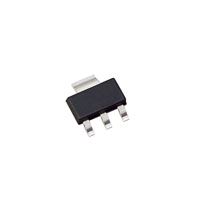
Sure . . . or go to a bigger device. The 3-terminal regulators come
in a range of sizes. The smallest are
[img]cid:.0[/img]
6 x 4 mm on a side, solder right to the board, and as you
might expect, cannot dissipate much power. They're good
for 100-500 mA max . . . but if your needs are small . . .
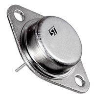
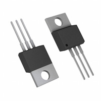
At the other end of the spectrum, you can buy these guys
[img]cid:.1[/img]
Rated for 5A and MUST be on a hefty heatsink. Furhter,
one can built arrays of transistors on even heftier
heatsinks perhaps cooled with fans.
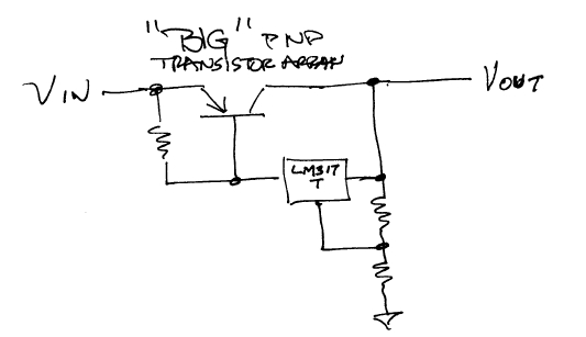
[img]cid:.2[/img]
I think the last time I built up something like this
it was to craft a finely adjustable 50A, 28v load bank.
There were 10 fat transistors on a big chunk of aluminum
cooled with a fan. This rig was good for 1400 watts
of room warming dissipation all controlled by a little
piece of plastic
[img]cid:.3[/img]
and a 1/2" diameter potentiometer.
The point to be made here is that the series-pass,
smart regulator can be crafted in just about any size
and output voltage within ratings limits for the
devices.
Bob . . .
| | - The Matronics AeroElectric-List Email Forum - | | | Use the List Feature Navigator to browse the many List utilities available such as the Email Subscriptions page, Archive Search & Download, 7-Day Browse, Chat, FAQ, Photoshare, and much more:
http://www.matronics.com/Navigator?AeroElectric-List |
|
| Description: |
|
| Filesize: |
4.32 KB |
| Viewed: |
20675 Time(s) |
|
| Description: |
|
| Filesize: |
16.57 KB |
| Viewed: |
20675 Time(s) |
|
| Description: |
|
| Filesize: |
32.63 KB |
| Viewed: |
20675 Time(s) |
|
| Description: |
|
| Filesize: |
12.32 KB |
| Viewed: |
20675 Time(s) |

|
|
|
| Back to top |
|
|
N20DG
Joined: 02 Jan 2008
Posts: 61
Location: lancaster, texas
|
| Posted: Tue Dec 14, 2010 9:54 am Post subject: Computing a Resistor Value |
|
|
Bob
Did you include a bunch of photos that Yahoo didn't like??
Just a wondering
Dick
In a message dated 12/14/2010 11:44:25 A.M. Central Standard Time, nuckolls.bob(at)aeroelectric.com writes:
| Quote: | Mornin' Al,
When I first read your post, I didn't think the resistor was the way to go, either,
same as Dick Tasker described. My thinking was you're asking quite a bit from just one
resistor.
My initial thought was "why not build a 5 volt circuit" (like this one)?
http://www.tkk.fi/Misc/Electronics/circuits/psu_5v.html
Recently, I asked this forum if they knew how I could turn my Ray Allen servo resistance
output (0-5K ohms) into a visual LED indicator. Our buddy Joe Gores offered the perfect suggestion
of a circuit referenced from Mike Linse.
Included in his suggestion was that really handy 5 volt circuit above, plus it is super easy to build.
The circuit had a final voltage output of 4.96 volts, and when combined with the circuit Mike Linse
talked about, the whole project worked exactly as I was hoping for.
From the article's data points about this 5 volt circuit, it says it may be limited to only
one amp, plus you should consider a heat sink. So I got to thinking.........
Here's a question for for you guys that rearrange electrons for a living.....could a guy
build TWO of these 5 volt circuits, and combine the '5 volt output' in parallel?
Sure . . . or go to a bigger device. The 3-terminal regulators come
in a range of sizes. The smallest are
6 x 4 mm on a side, solder right to the board, and as you
might expect, cannot dissipate much power. They're good
for 100-500 mA max . . . but if your needs are small . . .
At the other end of the spectrum, you can buy these guys
Rated for 5A and MUST be on a hefty heatsink. Furhter,
one can built arrays of transistors on even heftier
heatsinks perhaps cooled with fans.
I think the last time I built up something like this
it was to craft a finely adjustable 50A, 28v load bank.
There were 10 fat transistors on a big chunk of aluminum
cooled with a fan. This rig was good for 1400 watts
of room warming dissipation all controlled by a little
piece of plastic
and a 1/2" diameter potentiometer.
The point to be made here is that the series-pass,
smart regulator can be crafted in just about any size
and output voltage within ratings limits for the
devices.
Bob . . . |
| | - The Matronics AeroElectric-List Email Forum - | | | Use the List Feature Navigator to browse the many List utilities available such as the Email Subscriptions page, Archive Search & Download, 7-Day Browse, Chat, FAQ, Photoshare, and much more:
http://www.matronics.com/Navigator?AeroElectric-List |
|
| Description: |
|
| Filesize: |
4.32 KB |
| Viewed: |
20675 Time(s) |

|
| Description: |
|
| Filesize: |
16.57 KB |
| Viewed: |
20675 Time(s) |

|
| Description: |
|
| Filesize: |
32.63 KB |
| Viewed: |
20675 Time(s) |

|
| Description: |
|
| Filesize: |
12.32 KB |
| Viewed: |
20675 Time(s) |
|
|
|
| Back to top |
|
|
AlRice
Joined: 27 Sep 2007
Posts: 30
Location: Boca Raton, FL
|
| Posted: Tue Dec 14, 2010 4:41 pm Post subject: Re: Computing a Resistor Value |
|
|
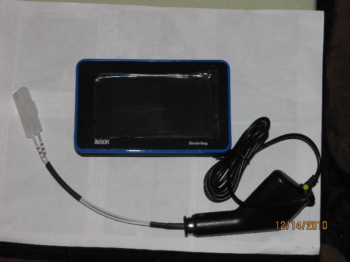
So, like I said, I chickened out and decided to use the car charger unit that came with the AV80R. I was able to pry the case apart and inside was a 1"x1" 12v-5v DC to DC power converter. I cut off the leads to the outside contacts and soldered on longer leads. For a case for the power converter, I simply used the existing one and routed the leads out the nose to a Molex plug. I'll secure the case behind the panel with an Adel clamp. Here is what it looks like.
| | - The Matronics AeroElectric-List Email Forum - | | | Use the List Feature Navigator to browse the many List utilities available such as the Email Subscriptions page, Archive Search & Download, 7-Day Browse, Chat, FAQ, Photoshare, and much more:
http://www.matronics.com/Navigator?AeroElectric-List |
|
| Description: |
|
| Filesize: |
70.68 KB |
| Viewed: |
20658 Time(s) |
|
_________________
Al Rice
Skybolt 260
RV-9A
Helping with my grandson's Piet |
|
| Back to top |
|
|
nuckolls.bob(at)aeroelect
Guest
|
| Posted: Tue Dec 14, 2010 7:33 pm Post subject: Computing a Resistor Value |
|
|
At 11:50 AM 12/14/2010, you wrote:
| Quote: | Bob
Did you include a bunch of photos that Yahoo didn't like??
Just a wondering
Dick
|
I guess I don't understand the question. Are you
having trouble seeing the images? You echoed the
posting back to me and they all appear as I originally
sent them.
Bob . . . [quote][b]
| | - The Matronics AeroElectric-List Email Forum - | | | Use the List Feature Navigator to browse the many List utilities available such as the Email Subscriptions page, Archive Search & Download, 7-Day Browse, Chat, FAQ, Photoshare, and much more:
http://www.matronics.com/Navigator?AeroElectric-List |
|
|
|
| Back to top |
|
|
N20DG
Joined: 02 Jan 2008
Posts: 61
Location: lancaster, texas
|
| Posted: Tue Dec 14, 2010 8:48 pm Post subject: Computing a Resistor Value |
|
|
All I got was blanks where a photo was supposed to be aka Blanks
Dick
In a message dated 12/14/2010 9:35:34 P.M. Central Standard Time, nuckolls.bob(at)aeroelectric.com writes:
| Quote: | At 11:50 AM 12/14/2010, you wrote:
| Quote: | Bob
Did you include a bunch of photos that Yahoo didn't like??
Just a wondering
Dick
|
I guess I don't understand the question. Are you
having trouble seeing the images? You echoed the
posting back to me and they all appear as I originally
sent them.
Bob . . . |
[quote][b]
| | - The Matronics AeroElectric-List Email Forum - | | | Use the List Feature Navigator to browse the many List utilities available such as the Email Subscriptions page, Archive Search & Download, 7-Day Browse, Chat, FAQ, Photoshare, and much more:
http://www.matronics.com/Navigator?AeroElectric-List |
|
|
|
| Back to top |
|
|
Bob McC
Joined: 09 Jan 2006
Posts: 258
Location: Toronto, ON
|
| Posted: Tue Dec 14, 2010 9:41 pm Post subject: Computing a Resistor Value |
|
|
Dick;
All of the pictures in both Bob’s original and your reply to him worked fine for me. No blanks. Must have something to do with your computer settings.
Bob McC
DO NOT ARCHIVE
From: owner-aeroelectric-list-server(at)matronics.com [mailto:owner-aeroelectric-list-server(at)matronics.com] On Behalf Of RGent1224(at)aol.com
Sent: Tuesday, December 14, 2010 11:44 PM
To: aeroelectric-list(at)matronics.com
Subject: Re: AeroElectric-List: Computing a Resistor Value
All I got was blanks where a photo was supposed to be aka Blanks
Dick
In a message dated 12/14/2010 9:35:34 P.M. Central Standard Time, nuckolls.bob(at)aeroelectric.com writes:
| Quote: |
At 11:50 AM 12/14/2010, you wrote: <![if !supportLineBreakNewLine]> <![endif]>
Bob
Did you include a bunch of photos that Yahoo didn't like??
Just a wondering
Dick
I guess I don't understand the question. Are you
having trouble seeing the images? You echoed the
posting back to me and they all appear as I originally
sent them.
<![if !supportLineBreakNewLine]> <![endif]>
Bob . . . | Quote: | | tp://www.aeroelectric.com/">www.aeroelectric.com/ href="http://www.buildersbooks.com/">www.buildersbooks.comhttp://www.homebuilthelp.com/">www.homebuilthelp.comp://www.matronics.com/contribution">http://www.matronics.com/contributionist href="http://www.matronics.com/Navigator?AeroElectric-List">http://www.matronics.com/Navigator?AeroElectric-Lists.matronics.com/">http://forums.matronics.com |
|
0123456789 | Quote: | | tp://www.aeroelectric.com/">www.aeroelectric.com |
0 | Quote: | | tp://www.aeroelectric.com/">www.aeroelectric.com |
1 | Quote: | | tp://www.aeroelectric.com/">www.aeroelectric.com |
2 | Quote: | | tp://www.aeroelectric.com/">www.aeroelectric.com |
3 | Quote: | | tp://www.aeroelectric.com/">www.aeroelectric.com |
4 | Quote: | | tp://www.aeroelectric.com/">www.aeroelectric.com |
5 | Quote: | | tp://www.aeroelectric.com/">www.aeroelectric.com |
6 | Quote: | | tp://www.aeroelectric.com/">www.aeroelectric.com |
7 | Quote: | | tp://www.aeroelectric.com/">www.aeroelectric.com |
8 | Quote: | | tp://www.aeroelectric.com/">www.aeroelectric.com |
9 | Quote: | | / href="http://www.buildersbooks.com/">www.buildersbooks.com |
0 | Quote: | | / href="http://www.buildersbooks.com/">www.buildersbooks.com |
1 | Quote: | | / href="http://www.buildersbooks.com/">www.buildersbooks.com |
2 | Quote: | | / href="http://www.buildersbooks.com/">www.buildersbooks.com |
3 | Quote: | | / href="http://www.buildersbooks.com/">www.buildersbooks.com |
4 | Quote: | | / href="http://www.buildersbooks.com/">www.buildersbooks.com |
5 | Quote: | | / href="http://www.buildersbooks.com/">www.buildersbooks.com |
6
[quote][b]
| | - The Matronics AeroElectric-List Email Forum - | | | Use the List Feature Navigator to browse the many List utilities available such as the Email Subscriptions page, Archive Search & Download, 7-Day Browse, Chat, FAQ, Photoshare, and much more:
http://www.matronics.com/Navigator?AeroElectric-List |
|
_________________
Bob McC
Falco #908
(just starting) |
|
| Back to top |
|
|
N20DG
Joined: 02 Jan 2008
Posts: 61
Location: lancaster, texas
|
| Posted: Wed Dec 15, 2010 6:08 am Post subject: Computing a Resistor Value |
|
|
Ok, Thanks, This is the only E-Mail this has happened on.
So I'll try to access it thru the group site
Thanks
Dick
In a message dated 12/14/2010 11:42:06 P.M. Central Standard Time, robert.mccallum2(at)sympatico.ca writes:
| Quote: |
Dick;
All of the pictures in both Bobâs original and your reply to him worked fine for me. No blanks. Must have something to do with your computer settings.
Bob McC
DO NOT ARCHIVE
From: owner-aeroelectric-list-server(at)matronics.com [mailto:owner-aeroelectric-list-server(at)matronics.com] On Behalf Of RGent1224(at)aol.com
Sent: Tuesday, December 14, 2010 11:44 PM
To: aeroelectric-list(at)matronics.com
Subject: Re: Computing a Resistor Value
All I got was blanks where a photo was supposed to be aka Blanks
Dick
In a message dated 12/14/2010 9:35:34 P.M. Central Standard Time, nuckolls.bob(at)aeroelectric.com writes:
| Quote: |
At 11:50 AM 12/14/2010, you wrote:
Bob
Did you include a bunch of photos that Yahoo didn't like??
Just a wondering
Dick
I guess I don't understand the question. Are you
having trouble seeing the images? You echoed the
posting back to me and they all appear as I originally
sent them.
Bob . . . | Quote: | | tp://www.aeroelectric.com/">www.aeroelectric.com/ href="http://www.buildersbooks.com/">www.buildersbooks.comhttp://www.homebuilthelp.com/">www.homebuilthelp.comp://www.matronics.com/contribution">http://www.matronics.com/contributionist href="http://www.matronics.com/Navigator?AeroElectric-List">http://www.matronics.com/Navigator?AeroElectric-Lists.matronics.com/">http://forums.matronics.com |
|
0123456789 | Quote: | | tp://www.aeroelectric.com/">www.aeroelectric.com |
0 | Quote: | | tp://www.aeroelectric.com/">www.aeroelectric.com |
1 | Quote: | | tp://www.aeroelectric.com/">www.aeroelectric.com |
2 | Quote: | | tp://www.aeroelectric.com/">www.aeroelectric.com |
3 | Quote: | | tp://www.aeroelectric.com/">www.aeroelectric.com |
4 | Quote: | | tp://www.aeroelectric.com/">www.aeroelectric.com |
5 | Quote: | | tp://www.aeroelectric.com/">www.aeroelectric.com |
6 | Quote: | | tp://www.aeroelectric.com/">www.aeroelectric.com |
7 | Quote: | | tp://www.aeroelectric.com/">www.aeroelectric.com |
8 | Quote: | | tp://www.aeroelectric.com/">www.aeroelectric.com |
9 | Quote: | | / href="http://www.buildersbooks.com/">www.buildersbooks.com |
0 | Quote: | | / href="http://www.buildersbooks.com/">www.buildersbooks.com |
1 | Quote: | | / href="http://www.buildersbooks.com/">www.buildersbooks.com |
2 | Quote: | | / href="http://www.buildersbooks.com/">www.buildersbooks.com |
3 | Quote: | | / href="http://www.buildersbooks.com/">www.buildersbooks.com |
4 | Quote: | | / href="http://www.buildersbooks.com/">www.buildersbooks.com |
5 | Quote: | | / href="http://www.buildersbooks.com/">www.buildersbooks.com |
6
| Quote: | | / href="http://www.buildersbooks.com/">www.buildersbooks.com |
7
|
[quote][b]
| | - The Matronics AeroElectric-List Email Forum - | | | Use the List Feature Navigator to browse the many List utilities available such as the Email Subscriptions page, Archive Search & Download, 7-Day Browse, Chat, FAQ, Photoshare, and much more:
http://www.matronics.com/Navigator?AeroElectric-List |
|
|
|
| Back to top |
|
|
|
|
You cannot post new topics in this forum
You cannot reply to topics in this forum
You cannot edit your posts in this forum
You cannot delete your posts in this forum
You cannot vote in polls in this forum
You cannot attach files in this forum
You can download files in this forum
|
Powered by phpBB © 2001, 2005 phpBB Group
|

