 |
Matronics Email Lists
Web Forum Interface to the Matronics Email Lists
|
| View previous topic :: View next topic |
| Author |
Message |
ptag.dev(at)tiscali.co.uk
Guest
|
 Posted: Thu Jan 20, 2011 3:42 am Post subject: Main wing bushings Posted: Thu Jan 20, 2011 3:42 am Post subject: Main wing bushings |
 |
|
Hi! I understand that the late Barry Mellors did all the fuselage calcs. IMHO he was a brilliant engineer in all things aircraft and worked in his own self employed right doing lots of work for the Brazillian aircraft manufacturers Combine him with Don Dykins wing designer and you had the benefit of a wonderful combine. Unfortunately we obviously canât speak to Barry anymore to discuss the items you are interested in. However it may help you to understand that when the wing fails it fails forward. Like has been suggested âif it ainât broke donât try to fix it !â Barry, bless him, helped immensely with the engine mount design and PFA approval for the Jabiru 3300 engine mount and Iâm quite sure the aircraft would never have flown without his design skill and approach to the intransigence  of the PFA engineer of the time!
Regards
To all
Bob Harrison G-PTAG
From: owner-europa-list-server(at)matronics.com [mailto:owner-europa-list-server(at)matronics.com] On Behalf Of Kingsley Hurst
Sent: 20 January 2011 03:33
To: europa-list(at)matronics.com
Subject: Re: Re: Main wing bushings
Hello Will,
I am not suggesting there is any alternative for us as builders. The design "as is" obviously fits the bill so the old adage, "if it ain't broke, don't fix it" is appropriate.
From a designer's point of view however, if you inspect the various methods employed by sailplane manufacturers, there are possibly better ways of doing it. I have never seen a sailplane with the same set-up as the Europa but that doesn't mean there isn't any. Ivan Shaw did get some ideas from sailplanes so maybe he found one . . . . I dunno!
Cheers
Kingsley
do not archive
[quote]
---
| | - The Matronics Europa-List Email Forum - | | | Use the List Feature Navigator to browse the many List utilities available such as the Email Subscriptions page, Archive Search & Download, 7-Day Browse, Chat, FAQ, Photoshare, and much more:
http://www.matronics.com/Navigator?Europa-List |
|
|
|
| Back to top |
|
 |
budyerly(at)msn.com
Guest
|
| Posted: Thu Jan 20, 2011 7:31 pm Post subject: Main wing bushings |
|
|
<?xml:namespace prefix="v" /><?xml:namespace prefix="o" /><![endif]-->  Sorry guys if I don't understand the actual question about the bushes and  bearing loads!  I had to go back and try to picture the question, in  the mean time, Grahams analysis is spot on as usual.


 To visualize the loads read on to my miscellaneous drivel.


 The two spars are basically a set of scissors..  The pins lock the  spars together like a pair of scissors trying to cut a steel bar.  The pins  of course must go through the fuselage and each spar to hold the fuselage  gravity forces and translate the lift forces of the wings to the fuselage.

 The bushes distribute the load and the hardened pins take the lifting  loads as shear load.


 Essentially the fuselage (about 1100 lbs. loaded with down tail forces  added under G and acceleration as well as the radial Gs) hangs from the  pins.


 The spars bend under the vertical load.  Like a pair of scissors, that  is trying to cut through that solid steel bar stock, so picture the force  of your hands causing  the thin blades to bend, as you would  expect a thin long pair of scissors to twist, bending vertical and  laterally.

 Mod 52s rear socket and tube takes the forward element of the lift vector  (the lift of the wing near maximum is forward and up, really pulling on the  aft socket) and translates the load through root rib, to the rear  attach to the steel tube in fuselage which is under tension but does not  significantly contribute to the vertical lift load.


 Because the aircraft is fiberglass and it does move a bit under load, the  spars twist some under load.  The Mod 52s, 1/2 inch spar pip  pin, keeps the tip of the starboard spar in check and from slipping into  the control linkage under bending and twisting.  The spar strap deters  twist and spar separation under load from their at rest  positions.  The pins hardened strength allows it to not be  sheared by the huge shearing action of the two spars against the fuselage and  each other.


 So why doesn't the spar pin bend at the bush?  Picture the  fuselage weight is pulling down at the left cockpit bush, the left spar  (forward)  is pulling up, but the right spar (aft) is pushing  down, and the sum of the actions basically keeps the pin horizontal.  All  that force though is on only one 1/2 inch in diameter pin, and that is  one heck of  a lot of shearing force. Because it is over a short  distance (and our spars are tight together), we don't have to have microns  of tolerance in the pin to bushing fit.....The action of the spars against one  another brilliantly keeps the pin horizontal and not from bending upward at  the fuselage bush and slipping off the pins as one would expect at first  glance thinking of only one spar.


 It is a clean neat simple design.  Could it be better, you bet, but  can it be built by us simple beings easily and cost effective?  Probably  not, so do I want to change it?  No way, it isn't worth it.  Like you  all say, it ain't broke, so don't fix it.


 For you new builders, keep your bushes and spars at a reasonable tightness  and you will be fine.  If you must ream the bush a bit because the port pin  is too tight, you only need to ream a couple of thousandths normally.   A heated pin through the bushes works best, as Graham said before, to take  a slightly out of align bush and right it.  Don't panic at the fuselage  bush slop as the spars keep the pin horizontal.  Always use the spar strap  and the pip pin adjusted as per the manual with the washer to distribute the  load on the poor spar cup.  Don't substitute bolts for the wing pins  provided unless properly hardened.  If you own a classic, do a Mod  52/74 as it is great insurance.


 Regards to all and I hope to see you at Sun "n Fun.


 Bud Yerly

Custom Flight Creations, Inc.

www.customflightcreations.com

(813)  653-4989


 [quote]   ---
| | - The Matronics Europa-List Email Forum - | | | Use the List Feature Navigator to browse the many List utilities available such as the Email Subscriptions page, Archive Search & Download, 7-Day Browse, Chat, FAQ, Photoshare, and much more:
http://www.matronics.com/Navigator?Europa-List |
|
|
|
| Back to top |
|
|
peterz(at)zutrasoft.com
Guest
|
| Posted: Fri Jan 21, 2011 4:49 am Post subject: Main wing bushings |
|
|
Not to be argumentative or picky....but....


My original mental analysis was just as Bud has described - but Graham's

description contradicted the assumption that under positive high-G loads,

the main spar pins are indeed providing an upward force vector to the

cockpit module as originally (and intuitively) thought.


The reason being that both the forward and rear (your rear pin under tension

analysis is accurate tho) lift pins are indeed taking *all* of the downward

G-loading from the cockpit module, pushing upwards on the fuse, and the two

spar pins are actually pushing *downward* on the cockpit module

(disregarding the twisting vector on the main spar pins imparted by the

scissor action of the spars). Why? because the spars are actually bending in

a curve (think a smile) just as the entire wing is, and the root ends of the

spars are actually (relative to the fuse) higher as a result than the spar

pin positions. The spar is trying to impart it's smile shape onto the

vertical cockpit module surface - which is not going to comply.


I believe this analysis (Graham's)  is correct.   So the fuse is not hanging

on the spar pins during high-G loading as one would intuitively assume.


Cheers,

Pete


On Thu, Jan 20, 2011 at 10:26 PM, Bud Yerly <budyerly(at)msn.com> wrote:


[quote]  Sorry guys if I don't understand the actual question about the bushes and

 bearing loads!  I had to go back and try to picture the question, in the

 mean time, Grahams analysis is spot on as usual.


 To visualize the loads read on to my miscellaneous drivel.


 The two spars are basically a set of scissors..  The pins lock the spars

 together like a pair of scissors trying to cut a steel bar.  The pins of

 course must go through the fuselage and each spar to hold the fuselage

 gravity forces and translate the lift forces of the wings to the fuselage
| | - The Matronics Europa-List Email Forum - | | | Use the List Feature Navigator to browse the many List utilities available such as the Email Subscriptions page, Archive Search & Download, 7-Day Browse, Chat, FAQ, Photoshare, and much more:
http://www.matronics.com/Navigator?Europa-List |
|
|
|
| Back to top |
|
|
ptag.dev(at)tiscali.co.uk
Guest
|
| Posted: Fri Jan 21, 2011 12:27 pm Post subject: Main wing bushings |
|
|
Hi! I understand that the late Barry Mellors did all the fuselage calcs. IMHO he was a brilliant engineer in all things aircraft and worked in his own self employed right doing lots of work for the Brazillian aircraft manufacturers Combine him with Don Dykins wing designer and you had the benefit of a wonderful combine. Unfortunately we obviously canât speak to Barry anymore to discuss the items you are interested in. However it may help you to understand that when the wing fails it fails forward. Like has been suggested âif it ainât broke donât try to fix it !â
Regards
To all
Bob Harrison G-PTAG
From: owner-europa-list-server(at)matronics.com (owner-europa-list-server(at)matronics.com) [mailto:owner-europa-list-server(at)matronics.com] ([email][mailto:owner-europa-list-server(at)matronics.com][/email]) On Behalf Of Kingsley Hurst
Sent: 20 January 2011 03:33
To: europa-list(at)matronics.com (europa-list(at)matronics.com)
Subject: Re: Re: Main wing bushings
Hello Will,
I am not suggesting there is any alternative for us as builders. The design "as is" obviously fits the bill so the old adage, "if it ain't broke, don't fix it" is appropriate.
From a designer's point of view however, if you inspect the various methods employed by sailplane manufacturers, there are possibly better ways of doing it. I have never seen a sailplane with the same set-up as the Europa but that doesn't mean there isn't any. Ivan Shaw did get some ideas from sailplanes so maybe he found one . . . . I dunno!
Cheers
Kingsley
do not archive
[quote]
---
| | - The Matronics Europa-List Email Forum - | | | Use the List Feature Navigator to browse the many List utilities available such as the Email Subscriptions page, Archive Search & Download, 7-Day Browse, Chat, FAQ, Photoshare, and much more:
http://www.matronics.com/Navigator?Europa-List |
|
|
|
| Back to top |
|
|
budyerly(at)msn.com
Guest
|
| Posted: Sun Jan 23, 2011 9:15 pm Post subject: Main wing bushings |
|
|
 <?xml:namespace prefix="v" /><?xml:namespace prefix="o" /><![endif]--> [img]cid:001601cbbb85$27b74dc0$9678D4DA(at)adminPC[/img][img]cid:001701cbbb85$27b74dc0$9678D4DA(at)adminPC[/img] Photo E-mail [url=http://photos.msn.com/Viewing/Album.aspx?PST=8nK2AN1B!1LEiKSdooxx9v4CFFiF2tnPWP2mfc7Vl*sFUj2!vUzirO5TouaOzaO*BEOC0mA51!eASMb0hNQHNQ%24%24]Play slideshow[/url] | [url=http://photos.msn.com/viewing/Photos.aspx?pi_Type=SlideshowTask&Task=Download&stppData=&pi_ImagesOnly=1&Folder=nBuRgwTGIGjZPMtNhxCyPhYLUBR*bYP2KBLX6a88C1s%24&User=23IQaj7Z2BRqNO1wUECSpX*P0Ju9hSGI&pi_NoLogin=1]Download images [/url] Pete,
I really enjoyed our discussions, as you and Graham have excellent insight and the Lord knows I need a break from wiring.
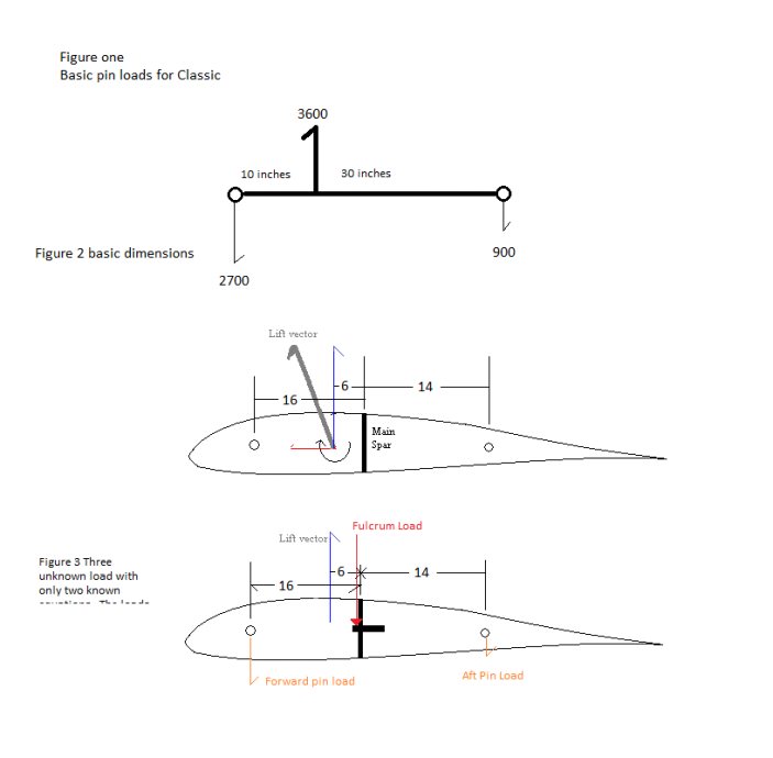
Just as you and others found it interesting that the side pins on the fuselage were designed to take all the load in lift and moments, I ran some basic calcs one Sun n Fun and it hit me why.
If you consider the wing sockets only it is a determinant structure and easy to calculate.
When the Europa was only 1300 lbs, like my Classic, I figured quick and dirty the following:
The GW is 1300 less wing weight is 1200, times ultimate of 6 Gs gives 7200 lbs load and 3600 pounds load born by the pins on each side.
Figure one below shows the balance beam idea. Of course we have to add pitching moment and the drag component doesn't go exactly through the pins and the dimensions were rough as shown in figure two. Considering 304 stainless pins are good for about 15Ksi in shear and at 1/2 inch diameter they can take a load of roughly 3000 lbs. The front pin holds about 2700 pounds and the rear pin about 900. So it was a slam dunk why it was calculated that way.
My instructors in college had a saying which was "the spar takes the lift and the root takes the moments" and that is something we, and I am sure the PFA, all remember. So the Europa design calculations indicate the main spar only translates the wing bending and the wing spar pins carry no lift load in the calculations. But who would buy an aircraft where the wing pins are not attached to anything but the spar themselves. After all if the wing sockets at the root carried all the load, we would only have an inspection plate in the fuselage back and we would rig the wings to the spar cup and side sockets only, then stick the other wing in, pin it and go fly. What do we need all that extra ply, aluminum and bushings for in the cockpit bulkhead? That is a lot of beef for just the spar bending loads and lateral shifting to be checked. That is unless it is redundant structure?
Further, if we increase the loading of the plane to 1450 lbs and then take the gust loading into consideration as well as temperature, the actual loading jumps up by a huge factor. We only had a reserve on that front pin of a few hundred pounds, now that pin/socket is going to be compromised.
If we consider the wing is supported at the main pins as a fulcrum say, we have the sum of forces and the sum of moments but three unknowns and we have an in-determinant structure as in figure three. If you assume the wing pin takes all the load as a see saw, then the spar bushes only have the moment load which is much less. Add in the point you made about the spar bending actually unloads the load its all gravy. So it seems without extensive strain gauge testing you can't get the design approved on the statement "well the pin is really not overstressed". We can't calculate the forces actually born by the pins unless we assume (ass out of u and me) some loadings.
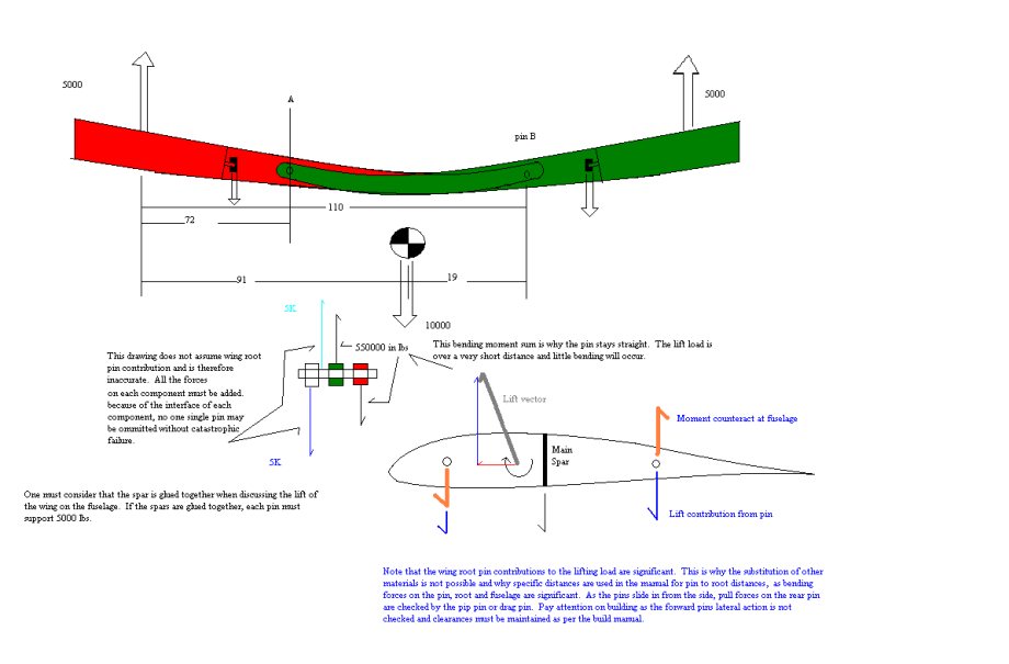
It is my feeling that the main wing pin does in fact take some of the lift load, greatly relieving that front pin. Any assigned loading on the bulkhead wing spar pins would significantly relieve the front socket. I believe this is born out by the fact that so many aircraft are flying well over gross weight and have flown uneventfully with no signs of stress on the forward pin and socket. Looking at the forward and rear socket, we also note that if a careless builder did not get the clearances as per the manual, bending on the pin would compromise the rib attachment as the glass could not stand the peel forces from the pin threads and disaster would ensue. A loss of any one pin would be catastrophic. If the front pin was removed, the rear pin may be able to take the load, but the root rib shear web may not be quite strong enough and the main spar cannot take any twisting so structural integrity will be lost. So to recap, the root rib, socket attaches, and pins are all critical.
Anyway, that is all I was commenting on. I'll leave the gross weight increase to Dave Goddard as he is a whole lot smarter than me. Other drawings and comments are provided below the three figures.
Regards to all,
Good night,
Bud
[url=http://photos.msn.com/Viewing/Album.aspx?PST=8nK2AN1B!1LEiKSdooxx9v4CFFiF2tnPWP2mfc7Vl*sFUj2!vUzirO5TouaOzaO*BEOC0mA51!eASMb0hNQHNQ%24%24][img]cid:001801cbbb85$27b74dc0$9678D4DA(at)adminPC[/img][/url]
[url=http://photos.msn.com/Viewing/Album.aspx?PST=8nK2AN1B!1LEiKSdooxx9v4CFFiF2tnPWP2mfc7Vl*sFUj2!vUzirO5TouaOzaO*BEOC0mA51!d384Ff4KCjNQ%24%24][img]cid:001901cbbb85$27b74dc0$9678D4DA(at)adminPC[/img][/url]
[quote] ---
| | - The Matronics Europa-List Email Forum - | | | Use the List Feature Navigator to browse the many List utilities available such as the Email Subscriptions page, Archive Search & Download, 7-Day Browse, Chat, FAQ, Photoshare, and much more:
http://www.matronics.com/Navigator?Europa-List |
|
| Description: |
|
| Filesize: |
842 Bytes |
| Viewed: |
8355 Time(s) |

|
| Description: |
|
| Filesize: |
1.11 KB |
| Viewed: |
8355 Time(s) |

|
| Description: |
|
| Filesize: |
31.26 KB |
| Viewed: |
8355 Time(s) |
|
| Description: |
|
| Filesize: |
57.97 KB |
| Viewed: |
8355 Time(s) |
|
|
|
| Back to top |
|
|
g-iani(at)ntlworld.com
Guest
|
| Posted: Mon Jan 24, 2011 4:38 am Post subject: Main wing bushings |
|
|
In support of Bud and Peteâs notes I can confirm that flexing of the fuselage is important. The LAA had considerable concerns that the tail dragger conversion would stiffen the structure in such a way that it could lead to overloading of the forward lift pin.
Ian Rickard G-IANI XS Trigear, 300hours
Europa Club Mods Specialist
e-mail g-iani(at)ntlworld.com
[quote][b]
| | - The Matronics Europa-List Email Forum - | | | Use the List Feature Navigator to browse the many List utilities available such as the Email Subscriptions page, Archive Search & Download, 7-Day Browse, Chat, FAQ, Photoshare, and much more:
http://www.matronics.com/Navigator?Europa-List |
|
|
|
| Back to top |
|
|
fklein(at)orcasonline.com
Guest
|
| Posted: Mon Jan 24, 2011 11:17 am Post subject: Main wing bushings |
|
|
On Jan 24, 2011, at 4:34 AM, G-IANI wrote:
| Quote: | In support of Bud and Petes notes I can confirm that flexing of the fuselage is important. The LAA had considerable concerns that the tail dragger conversion would stiffen the structure in such a way that it could lead to overloading of the forward lift pin.
|
BINGO !!
This is one of those times when I truly value this forum...I've been following this thread w/ only mild interest...to this non-engineer's mind, the assumed function of the lift pins was primarily to set and maintain the wings' AOA. But Ian's comment got my attention, and I have a newfound appreciation of all the posts leading up to it.
From the get go, I've been embedding components within my mono which would facilitate potential conversion to Bob Berube's tail dragger. I'd planned to add the recommended layups intended to transfer LG loads to the fuselage sides which have the effect of stiffening the sides of the fuselage. While I do not have the expertise to comment on the implications such layups may have on the loads ending up on the forward lift pins, I now will hold off on these layups...they can, after all, be easily added in the event the mono-ground handling proves troublesome...I may even get airborne a week earlier!
Fred
[quote][b]
| | - The Matronics Europa-List Email Forum - | | | Use the List Feature Navigator to browse the many List utilities available such as the Email Subscriptions page, Archive Search & Download, 7-Day Browse, Chat, FAQ, Photoshare, and much more:
http://www.matronics.com/Navigator?Europa-List |
|
|
|
| Back to top |
|
|
Duncan McFadyean
Joined: 18 Jan 2011
Posts: 225
|
| Posted: Mon Jan 24, 2011 2:02 pm Post subject: Main wing bushings |
|
|
<<.. would stiffen the structure in such a way that it could lead to overloading of the forward lift pin >>


Ian,

How does that work, if the lift pins are designed to carry the lift loads in the first place, there being no greater load available?!

Actually, it was stiffening in bending that might restrain rotation of the lift pin that was the issue, resulting in an additional bending load (not lift load) being applied to the forward lift pin. The LAA were offered a spherical socket that would articulate and remove the bending load on the pin, but declined to accept that.


However, you are on right path, The earlier discussion in this thread presumes that the spar flexes, as it indeed doe. But actually the spar (loaded in this direction) is the least flexible part of the whole system. What about the forward and aft portions of the root rib? Let’s say these ribs have equal section and ‘I’ as the spar, but being laid-up at +/- 45 degrees have x1.41 the elasticity of the unidirectional spar (in the direction of principal stress), added to which the length of these flexing root ribs (between lift pin and spar) is longer than the offset between lift pins and spar pins. So, as the root ribs will flex more than the spar and it follows that the “leverage” effect between the longitudinal offset of lift pin and spar pin centres is removed, or reversed to the extent that the spar pins share some lift load.


As you say, the flexing of the fus side also contributes, albeit this had to be stiffened-up to prevent pin disengagement.


Previously I have put a small finger down one of the (1/2”) spar pin holes with the wings rigged, while someone else rather violently loaded the wing, albeit not even near to 1g. But there was no hint of the “leverage” effect or the spar hole flexing downwards relative to the pin hole in the seat back.


Rgds.,

Duncan McF.


-----Original Message-----

 From: owner-europa-list-server(at)matronics.com [mailto:owner-europa-list-server(at)matronics.com] On Behalf Of G-IANI

 Sent: 24  January 2011 12:34

 To: europa-list(at)matronics.com

 Subject: RE: Re: Main wing bushings


In support of Bud and Pete’s notes I can confirm that flexing of the fuselage is important.  The LAA had considerable concerns that the tail dragger conversion would stiffen the structure in such a way that it could lead to overloading of the forward lift pin.


Ian Rickard G-IANI XS Trigear, 300hours

 Europa Club Mods Specialist

 e-mail g-iani(at)ntlworld.com


   [quote]   [b]
| | - The Matronics Europa-List Email Forum - | | | Use the List Feature Navigator to browse the many List utilities available such as the Email Subscriptions page, Archive Search & Download, 7-Day Browse, Chat, FAQ, Photoshare, and much more:
http://www.matronics.com/Navigator?Europa-List |
|
|
|
| Back to top |
|
|
budyerly(at)msn.com
Guest
|
| Posted: Mon Jan 24, 2011 3:12 pm Post subject: Main wing bushings |
|
|
<?xml:namespace prefix="v" /><?xml:namespace prefix="o" /><![endif]-->  This topic is a moving target, a lot like fiberglass...

 Most of the flex of the spars is in the thinner section reaching maximum  nearing the spar socket area.  The spar at the root does not move, and the  forward root rib is really quite stiff, the aft root rib portion is not as high  so it tends to flex a bit as stated.  The fuselage side on the other hand  is a bit flexi.  After repairing a couple aircraft, the  aircraft flexing spots tend to be the area just behind the rudder  pedal step, just forward of the windscreen on hard landings (when the floor  flexes), and between the front socket and the spar.  Interesting thing  is the Redux did not let go in any of the mishaps.  Tough stuff.


 Those looking at conventional gear, we must do considerable work to try to  get the landing gear loads closer to the fuselage sides to carry the torsional  load of the cantilever gear.  The cockpit module seat is not quite up to  the task.  To get a proper stance on the gear (read as taller in height),  the moment between the wheel and the fuselage on rough surfaces is quite high,  and a thin beam gear verses a wider gear beam and the actual  attach mechanism has to be analyzed and tested properly.

 All in due time.

 Bud

 [quote]   ---
| | - The Matronics Europa-List Email Forum - | | | Use the List Feature Navigator to browse the many List utilities available such as the Email Subscriptions page, Archive Search & Download, 7-Day Browse, Chat, FAQ, Photoshare, and much more:
http://www.matronics.com/Navigator?Europa-List |
|
|
|
| Back to top |
|
|
grahamsingleton(at)btinte
Guest
|
| Posted: Mon Jan 24, 2011 3:23 pm Post subject: Main wing bushings |
|
|
Not convinced Duncan. The spar resists bending and the leverage is enormous, from the centre of lift of the wing 30% span? The load on the root ribs is shear and some bending of the pins. Don't forget the lift load is a spread load whereas the spar bending of the tangs is a point load applied by the spar pins.
You are right about the stiffening of the fuselage side. We really should have flexible sockets at the LE as well as the TE.
I still believe the lift pins (in the root rib) should carry all the lift loads and the spar pins all the bending loads. That's why the tangs needed to be strengthened on the glider.
Graham
From: Duncan & Ami <ami-mcfadyean(at)talktalk.net>
To: europa-list(at)matronics.com
Sent: Monday, 24 January, 2011 21:58:21
Subject: RE: Re: Main wing bushings
<<.. would stiffen the structure in such a way that it could lead to overloading of the forward lift pin >>
Ian,
How does that work, if the lift pins are designed to carry the lift loads in the first place, there being no greater load available?!
Actually, it was stiffening in bending that might restrain rotation of the lift pin that was the issue, resulting in an additional bending load (not lift load) being applied to the forward lift pin. The LAA were offered a spherical socket that would articulate and remove the bending load on the pin, but declined to accept that.
However, you are on right path, The earlier discussion in this thread presumes that the spar flexes, as it indeed doe. But actually the spar (loaded in this direction) is the least flexible part of the whole system. What about the forward and aft portions of the root rib? Letâs say these ribs have equal section and âIâ as the spar, but being laid-up at +/- 45 degrees have x1.41 the elasticity of the unidirectional spar (in the direction of principal stress), added to which the length of these flexing root ribs (between lift pin and spar) is longer than the offset between lift pins and spar pins. So, as the root ribs will flex more than the spar and it follows that the âleverageâ effect between the longitudinal offset of lift pin and spar pin centres is removed, or reversed to the extent that the spar pins share some lift load.
As you say, the flexing of the fus side also contributes, albeit this had to be stiffened-up to prevent pin disengagement.
Previously I have put a small finger down one of the (1/2â) spar pin holes with the wings rigged, while someone else rather violently loaded the wing, albeit not even near to 1g. But there was no hint of the âleverageâ effect or the spar hole flexing downwards relative to the pin hole in the seat back.
Rgds.,
Duncan McF.
-----Original Message-----
From: owner-europa-list-server(at)matronics.com [mailto:owner-europa-list-server(at)matronics.com] On Behalf Of G-IANI
Sent: 24 January 2011 12:34
To: europa-list(at)matronics.com
Subject: RE: Re: Main wing bushings
In support of Bud and Peteâs notes I can confirm that flexing of the fuselage is important. The LAA had considerable concerns that the tail dragger conversion would stiffen the structure in such a way that it could lead to overloading of the forward lift pin.
Ian Rickard G-IANI XS Trigear, 300hours
Europa Club Mods Specialist
e-mail g-iani(at)ntlworld.com
0123456789012
[quote][b]
| | - The Matronics Europa-List Email Forum - | | | Use the List Feature Navigator to browse the many List utilities available such as the Email Subscriptions page, Archive Search & Download, 7-Day Browse, Chat, FAQ, Photoshare, and much more:
http://www.matronics.com/Navigator?Europa-List |
|
|
|
| Back to top |
|
|
nigel_graham(at)m-tecque.
Guest
|
| Posted: Tue Jan 25, 2011 12:37 am Post subject: Main wing bushings |
|
|
This has sparked an extremely interesting and thought provoking debate.
The only real solution is to model the aircraft using Finite Element Analysis to truly see how the airframe moves under differing load conditions.
Any Europa builders use FEA?
Nigel
On 24/01/2011 23:19, GRAHAM SINGLETON wrote: [quote] Not convinced Duncan. The spar resists bending and the leverage is enormous, from the centre of lift of the wing 30% span? The load on the root ribs is shear and some bending of the pins. Don't forget the lift load is a spread load whereas the spar bending of the tangs is a point load applied by the spar pins.
You are right about the stiffening of the fuselage side. We really should have flexible sockets at the LE as well as the TE.
I still believe the lift pins (in the root rib) should carry all the lift loads and the spar pins all the bending loads. That's why the tangs needed to be strengthened on the glider.
Graham
From: Duncan & Ami <ami-mcfadyean(at)talktalk.net> (ami-mcfadyean(at)talktalk.net)
To: europa-list(at)matronics.com (europa-list(at)matronics.com)
Sent: Monday, 24 January, 2011 21:58:21
Subject: RE: Re: Main wing bushings
<<.. would stiffen the structure in such a way that it could lead to overloading of the forward lift pin >>
Â
Ian,
How does that work, if the lift pins are designed to carry the lift loads in the first place, there being no greater load available?!
Actually, it was stiffening in bending that might restrain rotation of the lift pin that was the issue, resulting in an additional bending load (not lift load) being applied to the forward lift pin. The LAA were offered a spherical socket that would articulate and remove the bending load on the pin, but declined to accept that.
Â
However, you are on right path, The earlier discussion in this thread presumes that the spar flexes, as it indeed doe. But actually the spar (loaded in this direction) is the least flexible part of the whole system. What about the forward and aft portions of the root rib? Letâs say these ribs have equal section and âIâ as the spar, but being laid-up at +/- 45 degrees have x1.41 the elasticity of the unidirectional spar (in the direction of principal stress), added to which the length of these flexing root ribs (between lift pin and spar) is longer than the offset between lift pins and spar pins. So, as the root ribs will flex more than the spar and it follows that the âleverageâ effect between the longitudinal offset of lift pin and spar pin centres is removed, or reversed to the extent that the spar pins share some lift load.
Â
As you say, the flexing of the fus side also contributes, albeit this had to be stiffened-up to prevent pin disengagement.
Â
Previously I have put a small finger down one of the (1/2â) spar pin holes with the wings rigged, while someone else rather violently loaded the wing, albeit not even near to 1g. But there was no hint of the âleverageâ effect or the spar hole flexing downwards relative to the pin hole in the seat back.
Â
Rgds.,
Duncan McF.
Â
Â
-----Original Message-----
From: owner-europa-list-server(at)matronics.com (owner-europa-list-server(at)matronics.com) [mailto:owner-europa-list-server(at)matronics.com (owner-europa-list-server(at)matronics.com)] On Behalf Of G-IANI
Sent: 24 January 2011 12:34
To: europa-list(at)matronics.com (europa-list(at)matronics.com)
Subject: RE: Re: Main wing bushings
Â
In support of Bud and Peteâs notes I can confirm that flexing of the fuselage is important. The LAA had considerable concerns that the tail dragger conversion would stiffen the structure in such a way that it could lead to overloading of the forward lift pin.
Â
Â
Ian Rickard G-IANI XS Trigear, 300hours
Europa Club Mods Specialist
e-mail g-iani(at)ntlworld.com (g-iani(at)ntlworld.com)
Â
Â
 0 1 2 3 4 5 6 7 8 9 0 1 2 3
4
5 [b]
| | - The Matronics Europa-List Email Forum - | | | Use the List Feature Navigator to browse the many List utilities available such as the Email Subscriptions page, Archive Search & Download, 7-Day Browse, Chat, FAQ, Photoshare, and much more:
http://www.matronics.com/Navigator?Europa-List |
|
|
|
| Back to top |
|
|
flyingphil2
Joined: 04 Dec 2009
Posts: 117
|
| Posted: Tue Jan 25, 2011 2:03 am Post subject: Re: Main wing bushings |
|
|
All this talk of taildraggers has got me interested now .....


The new owners of Europa use FEA.  Also, I believe that they have scanned some or all of the aircraft.  They would therefore be the best people to do this if they were motivated.


Alternatively, this could be achieved through other channels if they were prepared to release the CAD data.  It's up to them really.
| | - The Matronics Europa-List Email Forum - | | | Use the List Feature Navigator to browse the many List utilities available such as the Email Subscriptions page, Archive Search & Download, 7-Day Browse, Chat, FAQ, Photoshare, and much more:
http://www.matronics.com/Navigator?Europa-List |
|
Last edited by flyingphil2 on Tue Jan 25, 2011 2:57 am; edited 1 time in total |
|
| Back to top |
|
|
grahamsingleton(at)btinte
Guest
|
| Posted: Tue Jan 25, 2011 2:13 am Post subject: Main wing bushings |
|
|
Anyone chat with them at the Dinner?

Graham

From: flyingphil2 <ptiller(at)lolacars.com>

To: europa-list(at)matronics.com

Sent: Tuesday, 25 January, 2011 10:03:43

Subject: Europa-List: Re: Main wing bushings


--> Europa-List message posted by: "flyingphil2" <ptiller(at)lolacars.com (ptiller(at)lolacars.com)>


All this talk of  taildraggers has got me interested now .....


The new owners of Europa use FEA.  Also, I believe that they have scanned some or all of the aircraft.  They would therefore be the best people to do this if they were motivated.


Alternatively, this could be achieved through other channels if they were prepared to release the CAD data.  It's up them really.


Read this topic online here:


http://forums.matronics.com/viewtopic.php?p=328374#328374


Navigator?Europa-List" target="_blank">http://www.matronics.com/Navigatorsp;              - MATRONICS WEB FORUMS -

=   -->
| | - The Matronics Europa-List Email Forum - | | | Use the List Feature Navigator to browse the many List utilities available such as the Email Subscriptions page, Archive Search & Download, 7-Day Browse, Chat, FAQ, Photoshare, and much more:
http://www.matronics.com/Navigator?Europa-List |
|
|
|
| Back to top |
|
|
wdaniell(at)etb.net.co
Guest
|
| Posted: Tue Jan 25, 2011 4:43 am Post subject: Main wing bushings |
|
|
Here is a question with respect to this topic â albeit a bit of a sensitive one. But maybe it is the acid test.
Is there any experience of this part of the aircraft failing apart? â I have heard of other failures but not any failures in this bit.
I assume that we have experience on the forum of extreme stress on the airframe amongst the forum members whether deliberately or as a result of turbulence.
So I guess the question is âdoes it work in practice?â
Will
From: owner-europa-list-server(at)matronics.com [mailto:owner-europa-list-server(at)matronics.com] On Behalf Of GRAHAM SINGLETON
Sent: 25 January, 2011 05:11
To: europa-list(at)matronics.com
Subject: Re: Re: Main wing bushings
Anyone chat with them at the Dinner?
Graham
From: flyingphil2 <ptiller(at)lolacars.com>
To: europa-list(at)matronics.com
Sent: Tuesday, 25 January, 2011 10:03:43
Subject: Re: Main wing bushings
--> Europa-List message posted by: "flyingphil2" <ptiller(at)lolacars.com (ptiller(at)lolacars.com)>
All this talk of taildraggers has got me interested now .....
The new owners of Europa use FEA. Also, I believe that they have scanned some or all of the aircraft. They would therefore be the best people to do this if they were motivated.
Alternatively, this could be achieved through other channels if they were prepared to release the CAD data. It's up them really.
[quote][b]
| | - The Matronics Europa-List Email Forum - | | | Use the List Feature Navigator to browse the many List utilities available such as the Email Subscriptions page, Archive Search & Download, 7-Day Browse, Chat, FAQ, Photoshare, and much more:
http://www.matronics.com/Navigator?Europa-List |
|
|
|
| Back to top |
|
|
kevinmarie(at)blueyonder.
Guest
|
| Posted: Tue Jan 25, 2011 10:10 am Post subject: Main wing bushings |
|
|
Hi
I have flown in mountain wave in a valley in the pyrenees. It was bad, my wife cried! I hope i never test the plane like that again. But the plane was and is fine.
Kevin
On 25 Jan 2011, at 12:39, "William Daniell" <wdaniell(at)etb.net.co (wdaniell(at)etb.net.co)> wrote:
[quote]
Here is a question with respect to this topic â albeit a bit of a sensitive one. But maybe it is the acid test.
Is there any experience of this part of the aircraft failing apart? â I have heard of other failures but not any failures in this bit.
I assume that we have experience on the forum of extreme stress on the airframe amongst the forum members whether deliberately or as a result of turbulence.
So I guess the question is âdoes it work in practice?â
Will
From: owner-europa-list-server(at)matronics.com (owner-europa-list-server(at)matronics.com) [mailto:owner-europa-list-server(at)matronics.com] On Behalf Of GRAHAM SINGLETON
Sent: 25 January, 2011 05:11
To: [url=mailto:europa-list(at)matronics.com]europa-list(at)matronics.com (europa-list(at)matronics.com)[/url]
Subject: Re: Re: Main wing bushings
Anyone chat with them at the Dinner?
Graham
From: flyingphil2 <ptiller(at)lolacars.com (ptiller(at)lolacars.com)>
To: [url=mailto:europa-list(at)matronics.com]europa-list(at)matronics.com (europa-list(at)matronics.com)[/url]
Sent: Tuesday, 25 January, 2011 10:03:43
Subject: Re: Main wing bushings
--> Europa-List message posted by: "flyingphil2" <[url=mailto:ptiller(at)lolacars.com]ptiller(at)lolacars.com (ptiller(at)lolacars.com)[/url]>
All this talk of taildraggers has got me interested now .....
The new owners of Europa use FEA. Also, I believe that they have scanned some or all of the aircraft. They would therefore be the best people to do this if they were motivated.
Alternatively, this could be achieved through other channels if they were prepared to release the CAD data. It's up them really.
[b]
| | - The Matronics Europa-List Email Forum - | | | Use the List Feature Navigator to browse the many List utilities available such as the Email Subscriptions page, Archive Search & Download, 7-Day Browse, Chat, FAQ, Photoshare, and much more:
http://www.matronics.com/Navigator?Europa-List |
|
|
|
| Back to top |
|
|
paul.the.aviator(at)gmail
Guest
|
| Posted: Tue Jan 25, 2011 11:54 am Post subject: Main wing bushings |
|
|
On Tuesday, January 25, 2011, Kevin Challis <kevinmarie(at)blueyonder.co.uk> wrote:
| Quote: | Hi
I have flown in mountain wave in a valley in the pyrenees. It was bad, my wife cried! I hope i never test the plane like that again. But the plane was and is fine.
Kevin
|
I had ATC vector me into a big ass'd cloud one time. Instead of
responding 'unable' I took the vector. Gee it was bad, really bad. My
wife didn't cry but I nearly did. The plane was fine and I was a
little smarter. I'm pretty sure I am going to break before my Europa
does
Paul
| | - The Matronics Europa-List Email Forum - | | | Use the List Feature Navigator to browse the many List utilities available such as the Email Subscriptions page, Archive Search & Download, 7-Day Browse, Chat, FAQ, Photoshare, and much more:
http://www.matronics.com/Navigator?Europa-List |
|
|
|
| Back to top |
|
|
Duncan McFadyean
Joined: 18 Jan 2011
Posts: 225
|
| Posted: Tue Jan 25, 2011 2:14 pm Post subject: Main wing bushings |
|
|
Graham,

I agree with all that you say, so unsure why you’re not convinced.

The lift load is spread on the wings, but comes to a point at the lift pins; the stress path being either via the spar and root rib, and/or directly through the wing skin to the root rib (assuming for the argument no lift contribution from the spar pins).

I recall that when a Europa wing broke in the early tests, it broke across the D-box (LE of wing) adjacent to the rib (and was subsequently reinforced in that area).

Meaning that this part was overstressed, obviously, but the strain at failure (being a material constant) was greatest in this part of the structure (i.e. up to the point of failure, the area around the rib had flexed more than any other part of similar ‘I).


Duncan.


-----Original Message-----

 From: owner-europa-list-server(at)matronics.com [mailto:owner-europa-list-server(at)matronics.com] On Behalf Of GRAHAM SINGLETON

 Sent: 24 January 2011 23:20

 To: europa-list(at)matronics.com

 Subject: Re: Re: Main wing bushings


Not convinced Duncan. The spar resists bending and the leverage is enormous, from the centre of lift of the wing 30% span? The load on the root ribs is shear and some bending of the pins. Don't forget the lift load is a spread load whereas the spar bending of the tangs is a point load applied by the spar pins.

 You  are right about the stiffening of the fuselage side. We really should have flexible sockets at the LE as well  as the TE.

 I still believe the lift pins (in the root rib) should carry all the lift loads and the spar pins all the bending loads. That's why the tangs needed to be strengthened on the glider.


 Graham


From: Duncan & Ami <ami-mcfadyean(at)talktalk.net>

 To: europa-list(at)matronics.com

 Sent: Monday, 24 January, 2011 21:58:21

 Subject: RE: Re: Main wing bushings

<<.. would stiffen the structure in such a way that it could lead to overloading of the forward lift pin >>


Ian,

How does that work, if the lift pins are designed to carry the lift loads in the first place, there being no greater load available?!

Actually, it was stiffening in bending that might restrain rotation of the lift pin that was the issue, resulting in an additional bending load (not lift load) being applied to the forward lift pin. The LAA were offered a spherical socket that would articulate and remove the bending load on the pin, but declined to accept that.


However, you are on right path, The earlier discussion in this thread presumes that the spar flexes, as it indeed doe. But actually the spar (loaded in this direction) is the least flexible part of the whole system. What about the forward and aft portions of the root rib? Let’s say these ribs have equal section and ‘I’ as the spar, but being laid-up at +/- 45 degrees have x1.41 the elasticity of the unidirectional spar (in the direction of principal stress), added to which the length of these flexing root ribs (between lift pin and spar) is longer than the offset between lift pins and spar pins. So, as the root ribs will flex more than the spar and it follows that the “leverage” effect between the longitudinal offset of lift pin and spar pin centres is removed, or reversed to the extent that the spar pins share some lift load.


As you say, the flexing of the fus side also contributes, albeit this had to be stiffened-up to prevent pin disengagement.


Previously I have put a small finger down one of the (1/2”) spar pin holes with the wings rigged, while someone else rather violently loaded the wing, albeit not even near to 1g. But there was no hint of the “leverage” effect or the spar hole flexing downwards relative to the pin hole in the seat back.


Rgds.,

Duncan McF.


-----Original Message-----

 From: owner-europa-list-server(at)matronics.com [mailto:owner-europa-list-server(at)matronics.com] On Behalf Of G-IANI

 Sent: 24 January 2011 12:34

 To: europa-list(at)matronics.com

 Subject: RE: Re: Main wing bushings


In support of Bud and Pete’s notes I can confirm that flexing of the fuselage is important.  The LAA had considerable concerns that the tail dragger conversion would stiffen the structure in such a way that it could lead to overloading of the forward lift pin.


Ian Rickard G-IANI XS Trigear, 300hours

 Europa Club Mods Specialist

 e-mail g-iani(at)ntlworld.com


   [quote]  http://www.matronics.com/Navigator?Europa-Listhttp://forums.matronics.comhttp://www.matronics.com/contribution   " target="_blank" href="http://forums.matronics.com">http://forums.matr   --> [/url] [url=http://www.matronic=======%0d%0a%0d%0a%3c/font%3e%3c/b%3e%3cfont%20color=][url=http://www.matronic=======%0d%0a%0d%0a%3c/font%3e%3c/b%3e%3cfont%20color=][url=http://www.matronic=======%0d%0a%0d%0a%3c/font%3e%3c/b%3e%3cfont%20color=][url=http://www.matronic=======%0d%0a%0d%0a%3c/font%3e%3c/b%3e%3cfont%20color=][b][u]http://www.matronics.com/Navigator?Europa-List [b]
| | - The Matronics Europa-List Email Forum - | | | Use the List Feature Navigator to browse the many List utilities available such as the Email Subscriptions page, Archive Search & Download, 7-Day Browse, Chat, FAQ, Photoshare, and much more:
http://www.matronics.com/Navigator?Europa-List |
|
|
|
| Back to top |
|
|
Duncan McFadyean
Joined: 18 Jan 2011
Posts: 225
|
| Posted: Tue Jan 25, 2011 2:26 pm Post subject: Main wing bushings |
|
|
Phil,

Those with early ("proper"!!) taildraggers were required by LAA to check

that the forward lift pins had not bent, because of suspicion (paranoia?) of

overload in bending. None were found bent. I checked mine again at 300 hours

(still die-straight, but probably hadn't seen more than 2g in flight (and up

to -4g of the wing weight only in landing!).


Also at an earlier time, I measured directly the relative bending stiffness

of the forward lift pin socket/fuselage combination on a number of Europas,

both taildragger, monowheel and one that had not yet had the standard inner

fuselage side stiffener built in. There was a lot of variation in this

stiffness, with the taildragger sockets being stiffer than the standard

build configuration.

However, none were as stiff as the rear (non articulated) sockets of the

original 1300lb MTWA Classic, albeit the rear lift pin only takes about half

of the load of the forward lift pin.

Duncan McF.


--
| | - The Matronics Europa-List Email Forum - | | | Use the List Feature Navigator to browse the many List utilities available such as the Email Subscriptions page, Archive Search & Download, 7-Day Browse, Chat, FAQ, Photoshare, and much more:
http://www.matronics.com/Navigator?Europa-List |
|
|
|
| Back to top |
|
|
Duncan McFadyean
Joined: 18 Jan 2011
Posts: 225
|
| Posted: Tue Jan 25, 2011 2:32 pm Post subject: Main wing bushings |
|
|
Bud,

It sounds like you could ‘kill two birds with one stone’ by adopting the design of fuselage reinforcements that the Swiss taildragger uses. If you’ve not seen these I’ll send you an isometric sketch.


Duncan McF


-----Original Message-----

 From: owner-europa-list-server(at)matronics.com [mailto:owner-europa-list-server(at)matronics.com] On Behalf Of Bud Yerly

 Sent: 24 January 2011 23:09

 To: europa-list(at)matronics.com

 Subject: Re: Re: Main wing bushings


This topic is a moving target, a lot like fiberglass...


Most of the flex of the spars is in the thinner section reaching maximum nearing the spar socket area.  The spar at the root does not move, and the forward root rib is really quite stiff, the aft root rib portion is not as high so it tends to flex a bit as stated.  The fuselage side on the other hand is a bit flexi.  After repairing a couple aircraft, the aircraft flexing spots tend to be the area just behind the rudder pedal step, just forward of the windscreen on hard landings (when the floor flexes), and between the front socket and the spar.  Interesting thing is the Redux did not let go in any of the mishaps.  Tough stuff.


Those looking at conventional gear, we must do considerable work to try to get the landing gear loads closer to the fuselage sides to carry the torsional load of the cantilever gear.  The cockpit module seat is not quite up to the task.  To get a proper stance on the gear (read as taller in height), the moment between the wheel and the fuselage on rough surfaces is quite high, and a thin beam gear verses a wider gear beam and the actual attach mechanism has to be analyzed and tested properly.


All in due time.


Bud

  [quote]

----- Original Message -----


From: Duncan & Ami (ami-mcfadyean(at)talktalk.net)


To: europa-list(at)matronics.com (europa-list(at)matronics.com)


Sent: Monday, January 24, 2011 4:58 PM


Subject: RE: Re: Main wing bushings


<<.. would stiffen the structure in such a way that it could lead to overloading of the forward lift pin >>


.Ian,

How does that work, if the lift pins are designed to carry the lift loads in the first place, there being no greater load available?!

Actually, it was stiffening in bending that might restrain rotation of the lift pin that was the issue, resulting in an additional bending load (not lift load) being applied to the forward lift pin. The LAA were offered a spherical socket that would articulate and remove the bending load on the pin, but declined to accept that.


However, you are on right path, The earlier discussion in this thread presumes that the spar flexes, as it indeed doe. But actually the spar (loaded in this direction) is the least flexible part of the whole system. What about the forward and aft portions of the root rib? Let's say these ribs have equal section and 'I' as the spar, but being laid-up at +/- 45 degrees have x1.41 the elasticity of the unidirectional spar (in the direction of principal stress), added to which the length of these flexing root ribs (between lift pin and spar) is longer than the offset between lift pins and spar pins. So, as the root ribs will flex more than the spar and it follows that the "leverage" effect between the longitudinal offset of lift pin and spar pin centres is removed, or reversed to the extent that the spar pins share some lift load.


As you say, the flexing of the fus side also contributes, albeit this had to be stiffened-up to prevent pin disengagement.


Previously I have put a small finger down one of the (1/2") spar pin holes with the wings rigged, while someone else rather violently loaded the wing, albeit not even near to 1g. But there was no hint of the "leverage" effect or the spar hole flexing downwards relative to the pin hole in the seat back.


Rgds.,

Duncan McF.


--
| | - The Matronics Europa-List Email Forum - | | | Use the List Feature Navigator to browse the many List utilities available such as the Email Subscriptions page, Archive Search & Download, 7-Day Browse, Chat, FAQ, Photoshare, and much more:
http://www.matronics.com/Navigator?Europa-List |
|
|
|
| Back to top |
|
|
grahamsingleton(at)btinte
Guest
|
| Posted: Tue Jan 25, 2011 5:21 pm Post subject: Main wing bushings |
|
|
Duncan
my problem is with the extra load on the lift pins when the spar bends, unnecessary. Maybe the fuse does relax but what's the point of adding a heavy belt when the braces have enough to do already! 
Graham
From: Duncan & Ami <ami-mcfadyean(at)talktalk.net>
To: europa-list(at)matronics.com
Sent: Tuesday, 25 January, 2011 22:10:16
Subject: RE: Re: Main wing bushings
Graham,
I agree with all that you say, so unsure why youâre not convinced.
The lift load is spread on the wings, but comes to a point at the lift pins; the stress path being either via the spar and root rib, and/or directly through the wing skin to the root rib (assuming for the argument no lift contribution from the spar pins).
I recall that when a Europa wing broke in the early tests, it broke across the D-box (LE of wing) adjacent to the rib (and was subsequently reinforced in that area).
Meaning that this part was overstressed, obviously, but the strain at failure (being a material constant) was greatest in this part of the structure (i.e. up to the point of failure, the area around the rib had flexed more than any other part of similar âI).
Duncan.
-----Original Message-----
From: owner-europa-list-server(at)matronics.com [mailto:owner-europa-list-server(at)matronics.com] On Behalf Of GRAHAM SINGLETON
Sent: 24 January 2011 23:20
To: europa-list(at)matronics.com
Subject: Re: Europa-List: Re: Main wing bushings
Not convinced Duncan. The spar resists bending and the leverage is enormous, from the centre of lift of the wing 30% span? The load on the root ribs is shear and some bending of the pins. Don't forget the lift load is a spread load whereas the spar bending of the tangs is a point load applied by the spar pins.
You are right about the stiffening of the fuselage side. We really should have flexible sockets at the LE as well as the TE.
I still believe the lift pins (in the root rib) should carry all the lift loads and the spar pins all the bending loads. That's why the tangs needed to be strengthened on the glider.
Graham
From: Duncan & Ami <ami-mcfadyean(at)talktalk.net>
To: europa-list(at)matronics.com
Sent: Monday, 24 January, 2011 21:58:21
Subject: RE: Europa-List: Re: Main wing bushings
<<.. would stiffen the structure in such a way that it could lead to overloading of the forward lift pin >>
Ian,
How does that work, if the lift pins are designed to carry the lift loads in the first place, there being no greater load available?!
Actually, it was stiffening in bending that might restrain rotation of the lift pin that was the issue, resulting in an additional bending load (not lift load) being applied to the forward lift pin. The LAA were offered a spherical socket that would articulate and remove the bending load on the pin, but declined to accept that.
However, you are on right path, The earlier discussion in this thread presumes that the spar flexes, as it indeed doe. But actually the spar (loaded in this direction) is the least flexible part of the whole system. What about the forward and aft portions of the root rib? Letâs say these ribs have equal section and âIâ as the spar, but being laid-up at +/- 45 degrees have x1.41 the elasticity of the unidirectional spar (in the direction of principal stress), added to which the length of these flexing root ribs (between lift pin and spar) is longer than the offset between lift pins and spar pins. So, as the root ribs will flex more than the spar and it follows that the âleverageâ effect between the longitudinal offset of lift pin and spar pin centres is removed, or reversed to the extent that the spar pins share some lift load.
As you say, the flexing of the fus side also contributes, albeit this had to be stiffened-up to prevent pin disengagement.
Previously I have put a small finger down one of the (1/2â) spar pin holes with the wings rigged, while someone else rather violently loaded the wing, albeit not even near to 1g. But there was no hint of the âleverageâ effect or the spar hole flexing downwards relative to the pin hole in the seat back.
Rgds.,
Duncan McF.
-----Original Message-----
From: owner-europa-list-server(at)matronics.com [mailto:owner-europa-list-server(at)matronics.com] On Behalf Of G-IANI
Sent: 24 January 2011 12:34
To: europa-list(at)matronics.com
Subject: RE: Re: Main wing bushings
In support of Bud and Peteâs notes I can confirm that flexing of the fuselage is important. The LAA had considerable concerns that the tail dragger conversion would stiffen the structure in such a way that it could lead to overloading of the forward lift pin.
Ian Rickard G-IANI XS Trigear, 300hours
Europa Club Mods Specialist
e-mail g-iani(at)ntlworld.com
01234567890123456789
0
[quote][b]
| | - The Matronics Europa-List Email Forum - | | | Use the List Feature Navigator to browse the many List utilities available such as the Email Subscriptions page, Archive Search & Download, 7-Day Browse, Chat, FAQ, Photoshare, and much more:
http://www.matronics.com/Navigator?Europa-List |
|
|
|
| Back to top |
|
|
|
|
You cannot post new topics in this forum
You cannot reply to topics in this forum
You cannot edit your posts in this forum
You cannot delete your posts in this forum
You cannot vote in polls in this forum
You cannot attach files in this forum
You can download files in this forum
|
Powered by phpBB © 2001, 2005 phpBB Group
|

