 |
Matronics Email Lists
Web Forum Interface to the Matronics Email Lists
|
| View previous topic :: View next topic |
| Author |
Message |
nuckolls.bob(at)aeroelect
Guest
|
 Posted: Sun Mar 06, 2011 7:40 pm Post subject: Need help in reviewing Z10/8 arch for dual Lightspeed ign. Posted: Sun Mar 06, 2011 7:40 pm Post subject: Need help in reviewing Z10/8 arch for dual Lightspeed ign. |
 |
|
| Quote: | Some challenges I'm still scratching my head over include:
1) How best to wire the dual Lightspeed
electronic ignitions to ensure they see higher
than 8.5V during engine start to minimize chance of starter kickback.
|
Turn the ignition switches on after you hit the
starter button. The 'brownout' lasts but 100 milliseconds
or so. Is the 8.5v number from Lightspeed? I believe the
ignition systems run at well under 8.5 volts.
??? Don't understand Ign #1 sparking cylinders 1&2 and #2
ignition sparking 3&4 ??????
| Quote: | I'm using a Skytec 149-12LS starter (PMG) which
has the high current draw at start. Should I
move both Lightspeed ignitions to a Brownout Battery Bus?
|
No. I'd put one on a battery bus, the other on the
e-bus. If you were sparking all 4 cylinders with
EACH ignition system, then alternator-out ops would
call for turning one ignition OFF>
| Quote: | 2) My batteries are also located in the tailcone
due to W&B needs with about a 12ft run aft of
the firewall. I estimated the starter would see
about 10.3V after losses. Does this sound right?
|
That's fine.
| Quote: | 3) How best to wire my dual Grand Rapids
EFIS/AHRS and the Engine Info System (EIS 4000)
to enable them to be ON during engine start. I
want the EIS on to monitor engine vitals (oil
pressure). For the EFIS/AHRS…it can take up
to two minutes to align the AHRS, and I'd prefer
not to burn gas, make noise, and blow stuff around while I wait for alignment.
|
At engine idle? Don't you let things warm up a bit
before you drive off? I think there are plenty of
things on a well crafted check-list to soak up
2 minutes wile the AHRS gets up on its feet.
If you're charging off into the deep woods with this
airplane, battery maintenance is VERY high on the
list. I think I'd rather have a better payload and
one battery that's changed out often than two
batteries that need extra-ordinary attention.
| Quote: | I’d like everything ready, checklist
complete up to the point of "ignition", then
start up, and taxi away. I’m considering
moving the 2nd EFIS/AHRS to the Endurance bus
as well, or a Brownout Battery Bus.
|
Simpler is ALWAYS better if you can configure an
operating procedure that accommodates the special
needs for some accessories.
| Quote: | 4) Overall does the wiring schematic make
sense? What mistakes did I make? Can it be simplified?
|
Yes . . . none that I can see beyond questions cited above . . . and yes.
| Quote: | I've attached two versions of the
architecture. One is printable (4 pages) to
read, and the other screen viewable. I’ve
also attached my electrical bus load analysis.
|
Nice job
Bob . . .
| | - The Matronics AeroElectric-List Email Forum - | | | Use the List Feature Navigator to browse the many List utilities available such as the Email Subscriptions page, Archive Search & Download, 7-Day Browse, Chat, FAQ, Photoshare, and much more:
http://www.matronics.com/Navigator?AeroElectric-List |
|
|
|
| Back to top |
|
 |
plevyakh
Joined: 10 Jan 2011
Posts: 39
|
| Posted: Mon Mar 07, 2011 8:26 am Post subject: Re: Need help in reviewing Z10/8 arch for dual Lightspeed ig |
|
|
"Some challenges I'm still scratching my head over include:
1) How best to wire the dual Lightspeed electronic ignitions to ensure they see higher than 8.5V during engine start to minimize chance of starter kickback."
| Quote: | Bob Answer: Turn the ignition switches on after you hit the starter button. The 'brownout' lasts but 100 milliseconds or so. Is the 8.5v number from Lightspeed? I believe the ignition systems run at well under 8.5 volts.
??? Don't understand Ign #1 sparking cylinders 1&2 and #2 ignition sparking 3&4 ?????? |
I'd prefer a more elegant solution to what you suggest Bob. I know that's a simpler one....but with my spouse flying or others down the road....I'm sure that "ops manual bold face procedure" would get missed.
The Ign #1 sparking cylinders 1&2 and #2 ignition sparking #3 & 4 cylinders is a type O mistake in my schematic. I have updated it to "LSE CD Ignition Box #1, and LSE CD Ignition Box #2".
Per the LSE Install manual: "Dual systems can be connected to each other such that each system knows if the other one is operating. If one of the two systems is turned off or has failed, the remaining system will automatically shift its timing curve to provide optimum engine performance with one system. This eliminates the common power loss when one magneto is turned off. The extremely wide operating voltage range, from 5v-35v allows hand starting long after the electric starter has stopped due to a low battery."
You are correct on the Lightspeed operating voltages. Service Bulletin PL-2 dated 6/26/2006 state that the "minimum supply voltage for starting is 6.5 volts, and minimum operating voltage is 5.5 volts"
See URL here the Lightspeed Service bulletins: http://www.lightspeedengineering.com/News/ServiceBulletins.htm
Service Bulletin PL-1B addresses "Misfire during Start and Kickbacks"... This SB states that "unmodified systems shipped before 12/04 can misfire if the supply voltage drops below 8.5V repeated during cranking. This can only occur if the starter draws excessive current and the battery is not sized for that current requirement. .... Toggle switch operated systems have no tendency to misfire, (the issue was triggered by the rapid "on" / "off" "on" sequence of the key switch motion)."
I have U3+ versions of the Plasma Ignition boxes and I'm using TOGGLE switches. So I think my boxes are good to 6.5V min. for starting. I have an email to Klaus Savier at LSE to confirm this.
So if my starter sees ~10V, and my LSE Ignition box timing firing is good down to a starting voltage of 6.5V....should I NOT worry about a potential for misfire?
I'm thinking of that cold day scenario where it might be tough to get the engine started.
What I'm not clear on is what happens if main battery circuit or the brownout battery circuit drops down below the minimum starting voltage?
With a good battery maint. program, the probability is very low of an issue, but I'd still like to know how would the dual LSE Ignition systems respond?
I'm hoping that with the Dual system interconnect, the box on the circuit with voltage greater than min. starting voltage would still keep the timing in order and no issues with starting. I know this is a question for Klaus at LSE, but wondering if anyone with dual LSE ignitions can shed some light?
=====
"I'm using a Skytec 149-12LS starter (PMG) which has the high current draw at start. Should I move both Lightspeed ignitions to a Brownout Battery Bus?"
| Quote: | | Bob Answer: No. I'd put one on a battery bus, the other on the e-bus. If you were sparking all 4 cylinders with EACH ignition system, then alternator-out ops would call for turning one ignition OFF> |
Agreed. Each Ignition box sparkles all 4 cyl. So if main alternator is out, then I think my ops procedure would be:
1) MAIN L-60 ALTERNATOR FIELD CIRCUIT BREAKER - PULL
2) DC POWER MASTER SWITCH - OFF
- drops off main battery contactor (1amp) and main bus...saving amps
3) AUX SD-8 ALTERNATOR SWITCH - ON
- brings online SD-8 yielding 5.4 to 7.0 amps with 2150 prop RPM
4) EBUS ALTERNATE FEED SWITCH - ON
- provides power to endurance bus
5) LIGHTSPEED IGNITION #1 SWITCH - OFF
- to save 1.3amps from main battery drain
-------------------------------------------------------
LSE has a recommended Dual Power Supply wiring schematic. I've attached below, and link is also here. http://www.lightspeedengineering.com/Manuals/PS_Diagram.htm
Should I just simplify my dual batt brownout schematic and just use a single Shottky diode between the two as shown in LSE's schematic?
"3) How best to wire my dual Grand Rapids EFIS/AHRS and the Engine Info System (EIS 4000) to enable them to be ON during engine start. I want the EIS on to monitor engine vitals (oil pressure). For the EFIS/AHRS…it can take up to two minutes to align the AHRS, and I'd prefer not to burn gas, make noise, and blow stuff around while I wait for alignment."
| Quote: | Bob Answer: At engine idle? Don't you let things warm up a bit before you drive off? I think there are plenty of things on a well crafted check-list to soak up 2 minutes while the AHRS gets up on its feet.
If you're charging off into the deep woods with this airplane, battery maintenance is VERY high on the list. I think I'd rather have a better payload and one battery that's changed out often than two batteries that need extra-ordinary attention. |
"I’d like everything ready, checklist complete up to the point of "ignition", then start up, and taxi away. I’m considering moving the 2nd EFIS/AHRS to the Endurance bus as well, or a Brownout Battery Bus."
| Quote: | | Bob Answer: Simpler is ALWAYS better if you can configure an operating procedure that accommodates the special needs for some accessories. |
I prefer to find out issues with my EFIS/EIS system before engine start. In addition, Grand Rapids Tech. in their installation manual pg. 6-1, recommends in section 6.2 Power Connections:
"It is desirable to not have the display units and AHRS connected to the power supply supplying power to the engine starter during the engine start (to maximize current available for the starter, and possibly extend the life of the CCFL backlight in the display unit), this feature allows the fitting of a small (3-5AH) auxiliary battery to one of the power input connections provide power to the EFIS during engine start."
I could size the AUX/Brownout battery 17AH (15.3 lbs) down to a 5AH (5.9 lbs), but I do like the idea of two batteries the same size and swapping out one each year for a new one. An Aux. PC680 also gives me approx. 2.6hrs at an endurance bus load of 4.6 amps.
"4) Overall does the wiring schematic make sense? What mistakes did I make? Can it be simplified?"
| Quote: | Bob Answer: Yes . . . none that I can see beyond questions cited above . . . and yes.
Bob . . . |
Lastly, I wanted to add...You and the AEC forum are just an INCREDIBLE resource! THANK-YOU for writing the AEC book and providing a place for us electrical challenged guys to bang heads and build better airplanes!
| | - The Matronics AeroElectric-List Email Forum - | | | Use the List Feature Navigator to browse the many List utilities available such as the Email Subscriptions page, Archive Search & Download, 7-Day Browse, Chat, FAQ, Photoshare, and much more:
http://www.matronics.com/Navigator?AeroElectric-List |
|
| Description: |
| Glastar Electrical Schematic, v0.1, 7 Mar 2011 |
|
| Filesize: |
188.72 KB |
| Viewed: |
7556 Time(s) |
|
| Description: |
| Dual Power Supply for LSE Dual Ignition systems |
|
| Filesize: |
50.63 KB |
| Viewed: |
7556 Time(s) |
|
_________________
Howard Plevyak
GlaStar / Cincinnati, Ohio |
|
| Back to top |
|
|
plevyakh
Joined: 10 Jan 2011
Posts: 39
|
| Posted: Tue Mar 15, 2011 4:07 pm Post subject: Re: Need help in reviewing Z10/8 arch for dual Lightspeed ig |
|
|
Bob, Carlos and AEC list,
I've revised my architecture diagram after absorbing the feedback. I agree I have no need for the brownout battery (Z10/ architecture. Since the LSE Plasma III's are good for starting voltage down to 6.5V.... architecture. Since the LSE Plasma III's are good for starting voltage down to 6.5V....
I no longer have a worry of starter kickback with my Skytec 149-12LS (PMG) starter.
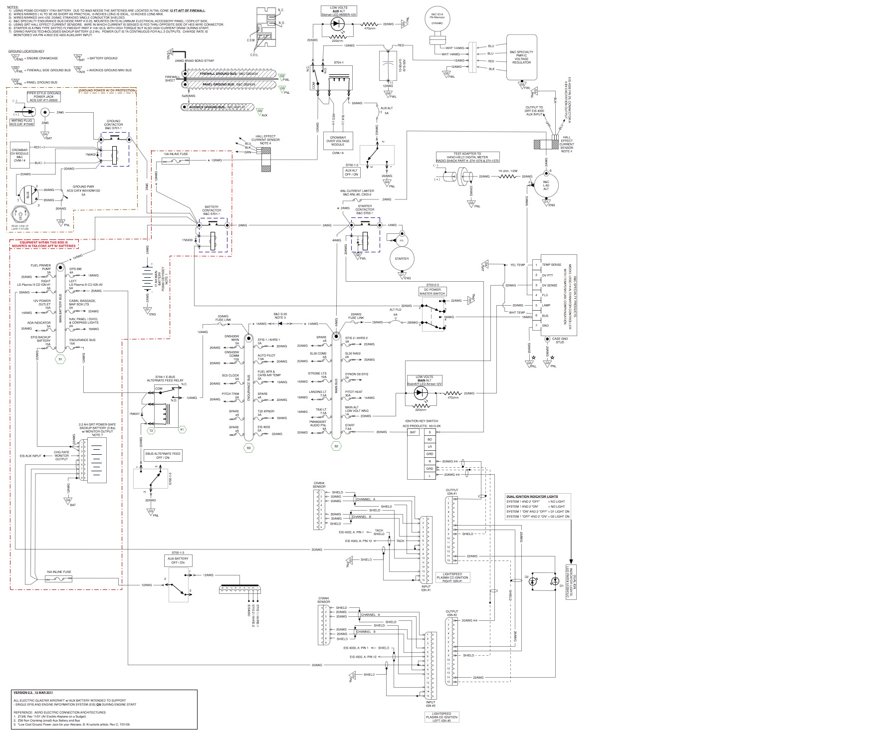
I switched back to a Z13/8 architecture as my base. I did include a very small (3 lb / 2.2Ah) battery to support my EFIS's, AHRS, and Engine Information System (EIS4000) to be ON prior to start.
Again, my reasoning for this is that I want to be able to turn on EFIS 1/AHRS 1 and EFIS 2/AHRS 2 to start the AHRS alignment since that can take up to two minutes. I also want the EIS on for oil pressure during start.
I'd like your feedback on this small AUX Battery circuit, since I wired the DC Power recharging feed from the Main Battery Bus direct. Is this a safe approach, or should I place a Diode in between Main BATT BUS, and the AUX BATT? If yes, what kind of diode?
As a follow up to prior post reply questions:
| Quote: | Bob Knuckoll's question:
"Is their installation/operation data published on the net anywhere?" |
Here's the link to the GRT EFIS Installation Manual.
http://www.grtavionics.com/File/Install%20Manuals/Horizon%20Install%20Rev%20A%20Feb%202009.pdf
All of their documents are found here:
http://www.grtavionics.com/default.aspx?id=4
Carlos also had a few questions:
| Quote: | | "(a) on the LOW VOLT warning light circuit for the SD8 Alternator....is this wrong in your schematic?" |
I pulled that off the B&C Power Distribution Diagram for the SD8. I've attached it below. It shows the alternator warning light coming off the Normally Closed tab thru the light, and then to ground.
Bob, did I wire this correctly for the SD8 Low Volt LED light in my architecture?
Carlos asked:
| Quote: | | b) Why did you connect the Fuel Primer pump to your "always hot" main battery bus?" |
I'm using the Van's Aircraft fuel priming system.
Link here: http://www.vansaircraft.com/cgi-bin/catalog.cgi?ident=1300231865-498-318&browse=engines&product=eng-prime
That circuit would be wired to the Parker Solenoid valve, via a 2-50:OFF-ON-(ON) progressive switch. With first click up PRIMER ON, and second click (Momentary) to give the engine a shot of primer.
Should this be moved to a different bus? Wondering why you ask.
Carlos asked:
| Quote: | | c) In this "always hot" main battery bus, you have a connection (lower left) called Endurance Bus, which is connected to the COM terminal of the S704-1 relay....Would you explain this connection and this relay function?" |
When you hit the starter button, the S704-1 brownout relay is energized and isolates the BROWNOUT BATT from the MAIN BATT.
My intention of using the brownout battery circuit was to isolate the brownout battery from the Main battery during engine start, such that the Endurance Bus received full volts to power my EFIS, EIS, and 2nd Plasma Ignition and NOT suffer a voltage drop due to the high initial current draw from the Skytec 149-12LS starter. But since I confirmed that my Plasma III Ignitions are good down to 6.5V, I took this circuit out.
--------
I look forward to your next round of feedback and questions. Sorry for the long post....but this is helping me solidify my architecture big time!
Thanks,
Howard
| | - The Matronics AeroElectric-List Email Forum - | | | Use the List Feature Navigator to browse the many List utilities available such as the Email Subscriptions page, Archive Search & Download, 7-Day Browse, Chat, FAQ, Photoshare, and much more:
http://www.matronics.com/Navigator?AeroElectric-List |
|
| Description: |
| GLASTAR SCHEMATIC Version 0.2, 15MAR2011. (Change: removed brownout battery circuit, added KEYed Ignition Switch, and small 2.2Ah AUX Battery) |
|
| Filesize: |
376.65 KB |
| Viewed: |
7480 Time(s) |
|
| Description: |
| SD8 Alternator Power Distribution Schematic |
|

Download |
| Filename: |
Power Distribution Diagram for Model SD8 Alternator.pdf |
| Filesize: |
1.03 MB |
| Downloaded: |
544 Time(s) |
| Description: |
| Printable version on 4 pages. |
|
Download |
| Filename: |
PRINTABLE_GLASTAR SCHEMATIC V0p2_15MAR2011 FOR REVIEW.pdf |
| Filesize: |
245.78 KB |
| Downloaded: |
675 Time(s) |
| Description: |
|
Download |
| Filename: |
GLASTAR SCHEMATIC V0p2_15MAR2011 FOR REVIEW.pdf |
| Filesize: |
222.78 KB |
| Downloaded: |
555 Time(s) |
_________________
Howard Plevyak
GlaStar / Cincinnati, Ohio |
|
| Back to top |
|
|
|
|
You cannot post new topics in this forum
You cannot reply to topics in this forum
You cannot edit your posts in this forum
You cannot delete your posts in this forum
You cannot vote in polls in this forum
You cannot attach files in this forum
You can download files in this forum
|
Powered by phpBB © 2001, 2005 phpBB Group
|

