 |
Matronics Email Lists
Web Forum Interface to the Matronics Email Lists
|
| View previous topic :: View next topic |
| Author |
Message |
nuckolls.bob(at)aeroelect
Guest
|
 Posted: Mon Mar 07, 2011 4:57 pm Post subject: Need help in reviewing Z10/8 arch for dual Lightspeed ign. Posted: Mon Mar 07, 2011 4:57 pm Post subject: Need help in reviewing Z10/8 arch for dual Lightspeed ign. |
 |
|
At 11:26 AM 3/7/2011, you wrote:
| Quote: |
"Some challenges I'm still scratching my head over include:
I'd prefer a more elegant solution to what you suggest Bob. I know
that's a simpler one....but with my spouse flying or others down the
road....I'm sure that "ops manual bold face procedure" would get missed.
|
| Quote: | Per the LSE Install manual: "Dual systems can be connected to each
other such that each system knows if the other one is operating. If
one of the two systems is turned off or has failed, the remaining
system will automatically shift its timing curve to provide optimum
engine performance with one system. This eliminates the common
power loss when one magneto is turned off. The extremely wide
operating voltage range, from 5v-35v allows hand starting long after
the electric starter has stopped due to a low battery.
|
| Quote: | You are correct on the Lightspeed operating voltages. Service
Bulletin PL-2 dated 6/26/2006 state that the "minimum supply voltage
for starting is 6.5 volts, and minimum operating voltage is 5.5 volts"
|
| Quote: | See URL here the Lightspeed Service bulletins:
http://www.lightspeedengineering.com/News/ServiceBulletins.htm
Service Bulletin PL-1B addresses "Misfire during Start and
Kickbacks"... This SB states that "unmodified systems shipped before
12/04 can misfire if the supply voltage drops below 8.5V repeated
during cranking. This can only occur if the starter draws excessive
current and the battery is not sized for that current requirement.
|
Which obviously will not be a condition on your airplane . . .
| Quote: | .... Toggle switch operated systems have no tendency to misfire,
(the issue was triggered by the rapid "on" / "off" "on" sequence of
the key switch motion)."
I have U3+ versions of the Plasma Ignition boxes and I'm using
TOGGLE switches. So I think my boxes are good to 6.5V min. for
starting. I have an email to Klaus Savier at LSE to confirm this.
|
Okay, a solution from Klaus's perspective would be a
software fix in his product so that sparking cannot commence
until the after two crank triggers are sensed . . . or
just a timing sequence that holds the system quiet until
a few hundred milliseconds after starter initiation.
But yes, I think you're worrying about something that
doesn't happen except in the most abusive of battery
conditions. The TC aircraft guys do lots of mystifying
things with their airplanes. I'm hoping that folks
who hang out here on the List will give their
battery choices AND maintenance and educated degree
of respect.
| Quote: | So if my starter sees ~10V, and my LSE Ignition box timing firing is
good down to a starting voltage of 6.5V....should I NOT worry about
a potential for misfire?
|
How does your ignition system voltage get to be anything
less than what the starter sees?
The brownout occurs during motor inrush . . . zero-rpm at
start=up means the starter draws stall current. Maybe
over 1000A with a good battery and stiff wiring. Here's
a plot I took off a GMC Safari with a wound field starter
and an RG battery
http://www.aeroelectric.com/Pictures/Curves/95_GMC_Safari_1.gif
Here's one I got off a Saturn with smaller engine, PM
starter and wet battery
http://www.aeroelectric.com/Pictures/Curves/99_Saturn_SL1.jpg
Here's another Saturn shot at higher resolution in time
http://www.aeroelectric.com/Pictures/Curves/99_Saturn_SL1_2.gif
Note that cranking current goes nowhere but down
and after 250 mS the battery V is up over 10V.
Airplane engines crank similarly.
| Quote: | I'm thinking of that cold day scenario where it might be tough to
get the engine started.
|
The concern is not for extended cranking but for the
initial effects of accelerating a very low resistance
PM motor.
| Quote: | What I'm not clear on is what happens if main battery circuit or the
brownout battery circuit drops down below the minimum starting voltage?
|
?? not sure about the point of the question. The
purpose of the brownout protection battery is to
insure this doesn't happen. Any time the voltage
drops below the manufacturer's specified minimums,
operating performance is not guaranteed. This doesn't
necessarily mean you should EXPECT any particular
symptom . . . unless those symptoms are also called
out by the manufacturer.
My general sense is that piling two batteries into
your airplane will have a negative effect on
payloads while adding no measurable or demonstrable
benefits.
| Quote: | With a good battery maint. program, the probability is very low of
an issue, but I'd still like to know how would the dual LSE Ignition
systems respond?
I'm hoping that with the Dual system interconnect, the box on the
circuit with voltage greater than min. starting voltage would still
keep the timing in order and no issues with starting. I know this
is a question for Klaus at LSE, but wondering if anyone with dual
LSE ignitions can shed some light?
|
That 'timing' issue is for RUNNING operations only
and is a very small issue at that. ALL starting ops
are after top dead center irrespective of how many
ignitions are running. And as I mentioned before,
alternator out ops should call for shutting one
system off . . . even if it did result in a slight
reduction of power. Your PLAN-B needs to acknowledge
that a significant failure has occurred and subsequent
operations are designed for minimizing risk to a
happy ending of the flight . . . not keeping all
the electro-whizzies running.
| Quote: | Agreed. Each Ignition box sparkles all 4 cyl. So if main
alternator is out, then I think my ops procedure would be:
1) MAIN L-60 ALTERNATOR FIELD CIRCUIT BREAKER - PULL
|
No necessary. Circuit breakers are for protecting
wires, not switching equipment.
| Quote: | 2) DC POWER MASTER SWITCH - OFF
- drops off main battery contactor (1amp) and main bus...saving amps
|
And shuts off the main alternator.
| Quote: | 3) AUX SD-8 ALTERNATOR SWITCH - ON
- brings online SD-8 yielding 5.4 to 7.0 amps with 2150 prop RPM
4) EBUS ALTERNATE FEED SWITCH - ON
- provides power to endurance bus
|
DO THIS FIRST
| Quote: | 5) LIGHTSPEED IGNITION #1 SWITCH - OFF
- to save 1.3amps from main battery drain
|
Yup.
| Quote: | -------------------------------------------------------
LSE has a recommended Dual Power Supply wiring schematic. I've
attached below, and link is also here.
http://www.lightspeedengineering.com/Manuals/PS_Diagram.htm
Should I just simplify my dual batt brownout schematic and just use
a single Shottky diode between the two as shown in LSE's schematic?
|
No. One ignition from the main battery bus,
the other from the endurance bus. Each to have
it's own breaker and one system to enjoy dual
power sources no matter what. You don't need the
second battery/diode combo. If you're not putting
in Z-13/8, THEN you use the dual batteries/diode
configuration.
| Quote: | > Bob Answer: Simpler is ALWAYS better if you can configure an
operating procedure that accommodates the special needs for some accessories.
I prefer to find out issues with my EFIS/EIS system before engine
start. In addition, Grand Rapids Tech. in their installation manual
pg. 6-1, recommends in section 6.2 Power Connections:
"It is desirable to not have the display units and AHRS connected to
the power supply supplying power to the engine starter during the
engine start (to maximize current available for the starter,
|
This is B.S. Minor system loads are never an issue for
getting the engine started in an airplane with
a well maintained battery . . . i.e. one that's
traded out at intervals or when test limits are
not met.
| Quote: | and possibly extend the life of the CCFL backlight in the display
unit), this feature allows the fitting of a small (3-5AH) auxiliary
battery to one of the power input connections provide power to the
EFIS during engine start."
|
Hmmm . . . "possibly" . . . suggests these folks
may not understand their product. Either they have
explored the suitability of their device to join
the ranks of other products designed for the aircraft
environment . . . or they have not. See:
http://www.aeroelectric.com/articles/Philosophy/Whats_all_this_DO160_Stuff_Anyhow.pdf
If they have not, it would be better that they at least
tell the customer in what ways they chose to reduce
development costs. I'm not suggesting that low-cost
offerings are necessarily a poor value . . . but they
should KNOW exactly what things are at risk and why.
Is their installation/operation data published on the
'net anywere?
| Quote: | I could size the AUX/Brownout battery 17AH (15.3 lbs) down to a 5AH
(5.9 lbs), but I do like the idea of two batteries the same size and
swapping out one each year for a new one. An Aux. PC680 also gives
me approx. 2.6hrs at an endurance bus load of 4.6 amps.
|
Does this include support energy from the SD-8? Once
you add the SD-8, battery sizing for endurance shouldn't
be an issue.
| Quote: | Lastly, I wanted to add...You and the AEC forum are just an
INCREDIBLE resource! THANK-YOU for writing the AEC book and
providing a place for us electrical challenged guys to bang heads
and build better airplanes!
|
Folks on the List are as much a resource for me as I am
for them. I could write another book on the number
of products that never came into being purely
for reasons of regulatory, management or marketing
boondoggles.
That sort of thing wasn't happening in the heydays
of Walter, Duane and Willy. That's how I got to
put a speed regulated trim system on the 55 Lears . . .
which was so popular that it got retrofitted
to the fleet of 30 series airplanes and made my
boss a few $millions$.
I've chased much slicker products through
the rat-maze since but none have been so
satisfying . . . so I guess I could say
my career 'peaked' when I was 37. Not that
it hasn't been educational and fun. YOU
folks are my reason for thinking hard these
days . . . you're saving me from Alzheimer's.
So THANK YOU too!
Bob . . .
| | - The Matronics AeroElectric-List Email Forum - | | | Use the List Feature Navigator to browse the many List utilities available such as the Email Subscriptions page, Archive Search & Download, 7-Day Browse, Chat, FAQ, Photoshare, and much more:
http://www.matronics.com/Navigator?AeroElectric-List |
|
|
|
| Back to top |
|
 |
nuckolls.bob(at)aeroelect
Guest
|
| Posted: Tue Mar 15, 2011 9:36 pm Post subject: Need help in reviewing Z10/8 arch for dual Lightspeed ign. |
|
|
At 08:07 PM 3/15/2011, you wrote:
I switched back to a Z13/8 architecture as my base. I did include a
very small (3 lb / 2.2Ah) battery to support my EFIS's, AHRS, and
Engine Information System (EIS4000) to be ON prior to start.
Again, my reasoning for this is that I want to be able to turn on
EFIS 1/AHRS 1 and EFIS 2/AHRS 2 to start the AHRS alignment since
that can take up to two minutes. I also want the EIS on for oil
pressure during start.
I'd like your feedback on this small AUX Battery circuit, since I
wired the DC Power recharging feed from the Main Battery Bus
direct. Is this a safe approach, or should I place a Diode in
between Main BATT BUS, and the AUX BATT? If yes, what kind of diode?
If you're going to have a second battery, and particularly
if it is small, you don't want it being 'hit' by starter
draws. You might just as well wire it as a brown-out
battery a per Z10-8 so that it's automatically unhooked
from the main battery during cranking.
As a follow up to prior post reply questions:
Carlos also had a few questions:
> "(a) on the LOW VOLT warning light circuit for the SD8
Alternator....is this wrong in your schematic?"
Which drawing? Warning lights shown on any
of my drawings become surplus if you've got
lv warning built into other systems.
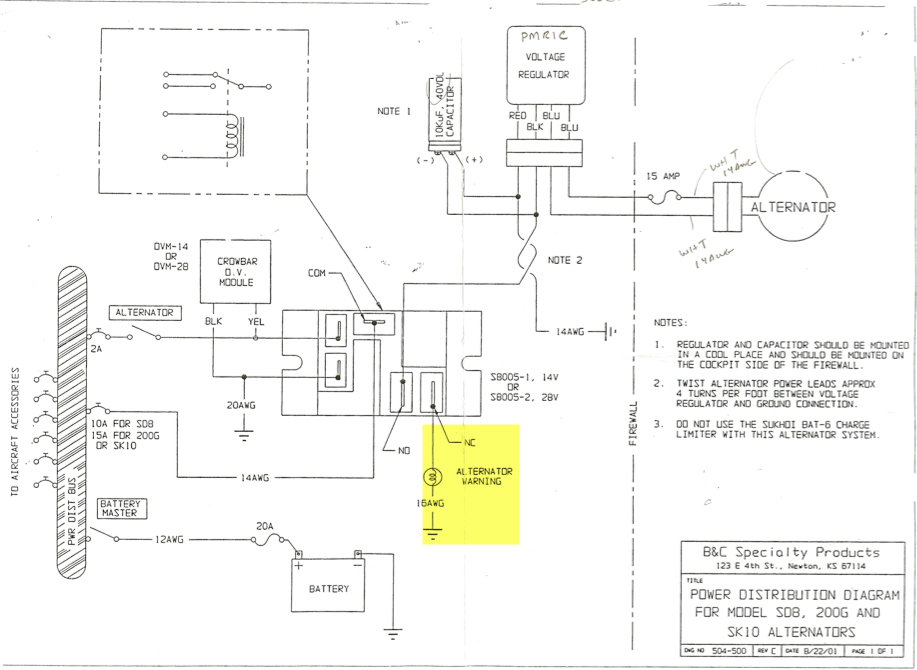
I pulled that off the B&C Power Distribution Diagram for the
SD8. I've attached it below. It shows the alternator warning light
coming off the Normally Closed tab thru the light, and then to ground.
Please don't mix/match features of multiple architecture
sources. Let's pick one Z-figure and adjust as necessary
to meet your needs. I'll suggest Z10-8
Bob, did I wire this correctly for the SD8 Low Volt LED light in my
architecture?
Do you need any more lights?
Carlos asked:
> b) Why did you connect the Fuel Primer pump to your "always hot"
main battery bus?"
I'm using the Van's Aircraft fuel priming system.
Link here:
http://www.vansaircraft.com/cgi-bin/catalog.cgi?ident=1300231865-498-318&browse=engines&product=eng-prime
That circuit would be wired to the Parker Solenoid valve, via a
2-50:OFF-ON-(ON) progressive switch. With first click up PRIMER ON,
and second click (Momentary) to give the engine a shot of primer.
Should this be moved to a different bus? Wondering why you ask.
Many moons ago, a couple of my readers installed 4-port
primer systems and add a needle valve to their
primer line such that flow to the engine was
about the same during priming as it might be for
75% power. The idea was that the primer system could
provide a po' boy's fuel injection system to back
up the normal fuel delivery pathway to a carburetor.
The topic came up again about 2006 when we talked
about ways to eliminate fuel selector valves and
their attendant risks for fuel leaks in the cockpit.
Here, the 4-port primer/injector system and a suits
of Facet pumps was proposed to eliminate all breaks
in plumbing to install valves, provide for priming,
and a second fuel delivery pathway.
http://aeroelectric.com/Pictures/Misc/All-Elect-Fuel.jpg
If your airplane is low wing and DEPENDS on a pump
for engine operation, then it seems a prudent thing
to have at least one ignition and required electric
fuel delivery to run from a battery bus. This
allows the electrical system to be configured for
'max cold' without killing the engine.
But since I confirmed that my Plasma III Ignitions are good down to
6.5V, I took this circuit out.
But you still have concerns for the avionics . . .
so the brown-out battery is the cleanest way/
Bob . . .
| | - The Matronics AeroElectric-List Email Forum - | | | Use the List Feature Navigator to browse the many List utilities available such as the Email Subscriptions page, Archive Search & Download, 7-Day Browse, Chat, FAQ, Photoshare, and much more:
http://www.matronics.com/Navigator?AeroElectric-List |
|
|
|
| Back to top |
|
|
plevyakh
Joined: 10 Jan 2011
Posts: 39
|
| Posted: Wed Mar 16, 2011 7:40 am Post subject: Re: Need help in reviewing Z10/8 arch for dual Lightspeed ig |
|
|
Bob,
Thanks for the quick reply. I'll make the tweaks.
Regarding your question on the SD8 Low Volt Warning light....
| Quote: | | "Which drawing? Warning lights shown on any of my drawings become surplus if you've got lv warning built into other systems. |
The only other LOW VOLT light I have is on the L-60 circuit.
Here's a clearer picture on my question regarding the SD8 Alternator LOW VOLT Warning light wiring. My goal here was that when running just on the SD8, I could use a low voltage warning for the SD-8 to indicate when the battery is actually carrying part of the load. At 2700 Prop RPM (SD8 (at) 3500 RPM) I get 8.4 to 10.1 amps with high fuel consumption. Having the Low Volt light allows me to make the tradeoff in flight, depending on the distance to destination.
I've sized my endurance bus to 3.7V....but if I wanted to keep some equipment on with the SD8 I'd like to be able to make that tradeoff to help get me down (assuming IFR, in the soup).
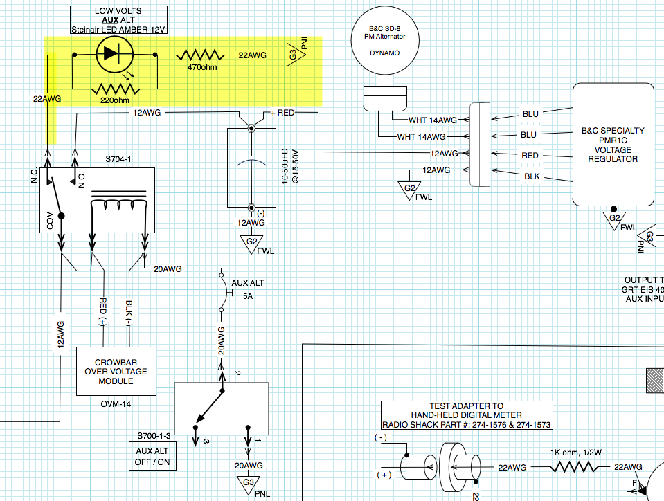
So directly my question is....by swapping in the LED light on the highlighted circuit is it wired correctly?
Since I couldn't find a Z-architecture that had this included, I used the B&C SD8 Power distribution diagram as reference on where to pull the light warning signal.
Also can you please explain how the OVM-14 module works in tripping the light to come on....or point me to one of your articles that explains that better. I'm not clear on how this works.
Thank-you,
Howard
| | - The Matronics AeroElectric-List Email Forum - | | | Use the List Feature Navigator to browse the many List utilities available such as the Email Subscriptions page, Archive Search & Download, 7-Day Browse, Chat, FAQ, Photoshare, and much more:
http://www.matronics.com/Navigator?AeroElectric-List |
|
| Description: |
| B&C Specialty SD8 Alternator Power Distribution Diagram showing how to wire with a Low Volt Warning (INCANDESCENT BULB) light. |
|
| Filesize: |
308.36 KB |
| Viewed: |
5060 Time(s) |
|
| Description: |
| Snipit of the SD8 Low Volt warning light circuit from my GlaStar schematic. |
|
| Filesize: |
171.32 KB |
| Viewed: |
5060 Time(s) |
|
_________________
Howard Plevyak
GlaStar / Cincinnati, Ohio |
|
| Back to top |
|
|
nuckolls.bob(at)aeroelect
Guest
|
| Posted: Wed Mar 16, 2011 3:57 pm Post subject: Need help in reviewing Z10/8 arch for dual Lightspeed ign. |
|
|
At 11:40 AM 3/16/2011, you wrote:
| Quote: |
Bob,
Thanks for the quick reply. I'll make the tweaks.
Regarding your question on the SD8 Low Volt Warning light....
> "Which drawing? Warning lights shown on any of my drawings become
surplus if you've got lv warning built into other systems.
The only other LOW VOLT light I have is on the L-60 circuit.
Here's a clearer picture on my question regarding the SD8 Alternator
LOW VOLT Warning light wiring. My goal here was that when running
just on the SD8, I could use a low voltage warning for the SD-8 to
indicate when the battery is actually carrying part of the load. At
2700 Prop RPM (SD8 (at) 3500 RPM) I get 8.4 to 10.1 amps with high
fuel consumption. Having the Low Volt light allows me to make the
tradeoff in flight, depending on the distance to destination.
|
These are NOT the kinds of things you want to be doing
in flight. When the big guy wanders off into the weeds,
then you should have a Plan-B for the little guy's
task. When A fails then B and continue flight to
airport of intended destination.
You don't need a light to tell you anything that
is pre-ordained by planing.
| Quote: | I've sized my endurance bus to 3.7V....but if I wanted to keep some
equipment on with the SD8 I'd like to be able to make that tradeoff
to help get me down (assuming IFR, in the soup).
|
You won't find a pilot's operating handbook anywhere that
has the crew flipping switches, taking measurements, and
crafting new plans based on real-time judgement calls
as an in-flight activity. When the main alternator fails,
craft a plan, test the plan, exercise the plan as necessary,
fly the airplane . . .
| Quote: | So directly my question is....by swapping in the LED light on the
highlighted circuit is it wired correctly?
|
That's not a "LOW VOLTS" warning light, it's an "ALT OFF"
annunciator.
| Quote: | Since I couldn't find a Z-architecture that had this included, I
used the B&C SD8 Power distribution diagram as reference on where to
pull the light warning signal.
|
Ditch that light. I was under the impression that
you had some form of Low Volts warning in one or more
of your panel mounted accessories. If not, then you need
some independent, timely, and insistent notification
like our 9005 DIY project or Eric's LV warning light
module.
| Quote: | Also can you please explain how the OVM-14 module works in tripping
the light to come on....or point me to one of your articles that
explains that better. I'm not clear on how this works.
|
See: Chapter 6 in the 'Connection.
Bob . . .
| | - The Matronics AeroElectric-List Email Forum - | | | Use the List Feature Navigator to browse the many List utilities available such as the Email Subscriptions page, Archive Search & Download, 7-Day Browse, Chat, FAQ, Photoshare, and much more:
http://www.matronics.com/Navigator?AeroElectric-List |
|
|
|
| Back to top |
|
|
|
|
You cannot post new topics in this forum
You cannot reply to topics in this forum
You cannot edit your posts in this forum
You cannot delete your posts in this forum
You cannot vote in polls in this forum
You cannot attach files in this forum
You can download files in this forum
|
Powered by phpBB © 2001, 2005 phpBB Group
|

