 |
Matronics Email Lists
Web Forum Interface to the Matronics Email Lists
|
| View previous topic :: View next topic |
| Author |
Message |
messydeer
Joined: 13 Feb 2006
Posts: 214
Location: Bellingham, WA
|
 Posted: Thu May 12, 2011 6:38 am Post subject: transponder connections, grounding and RF interference Posted: Thu May 12, 2011 6:38 am Post subject: transponder connections, grounding and RF interference |
 |
|
I've got a TDR-950 and now have the components ready for connecting it to my MGL Enigma.
Connections
I have a couple questions about where the wires connect. Bob has the pinout table here, http://www.aeroelectric.com/Installation_Data/TDR950-950L.pdf . Number 2 says 'ext suppr'. I read on VAF, http://www.vansairforce.com/community/showthread.php?t=3414, this is for DME, which I don't have so would leave open.
Number 3 is for D4. The Enigma installation manual says, 'If your transponder does not support signals D4 and D2, leave them unconnected.' The transponder doesn't have D2, so do I connect D4 or not?
Number 13 is for a 14v dimmer. I'm running a 14V system. On the front of the transponder there is an adjustable knob that says 'dim' and has a curved arrow around the knob. Would 13 go to power? If so, seems I could jump this into number 14, which says 14 volts DC in.
Number 15 says 'remote I/D'. The same thread on VAF said to ground this. Is that right?
Grounding
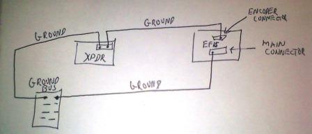
The pinout table says number 1 goes to ground and MGL says also to ground the xpdr to the encoder connection of the EFIS. The EFIS is also grounded separately from its main connector to the ground bus. Is this the way to do it? I'm concerned about ground loops. I've attached a schematic of what I think they are suggesting, showing just the ground wires.
Would 22awg be fine for any xpdr grounds? The 10 wire cable uses 24awg.
RF interference
I've also got a ferrite bead cylinder or two from MGL. Would I loop all the wires from the transponder through one of these, close to the back of the xpdr?
Thanks 
| | - The Matronics AeroElectric-List Email Forum - | | | Use the List Feature Navigator to browse the many List utilities available such as the Email Subscriptions page, Archive Search & Download, 7-Day Browse, Chat, FAQ, Photoshare, and much more:
http://www.matronics.com/Navigator?AeroElectric-List |
|
| Description: |
|
| Filesize: |
30.84 KB |
| Viewed: |
3136 Time(s) |
|
_________________
Dan |
|
| Back to top |
|
 |
messydeer
Joined: 13 Feb 2006
Posts: 214
Location: Bellingham, WA
|
| Posted: Fri May 13, 2011 7:38 am Post subject: Re: transponder connections, grounding and RF interference |
|
|
Below are some suggestions from other sources:


Pin #2 for 'ext suppr' is to be left open, since I'll have no DME.


Pin #3 for D4 could be connected to D4 or left open, since it would only be required over 30,000 ft.


Pin #14 for 14V dimmer: the 'dim' with curved arrow next to the 'reply ident' knob may be for the knob only, so an external dimmer might be needed. I hadn't planned on installing one and don't plan on night flying, so I may just wire a pigtail and leave it open.


Pin #15 for 'remote I/D' should be left open and not used as a ground connection.


The grounding schematic I posted earlier is correct, except that now that I will not be using pin #15 as a ground, I'll jumper the grounds from the ground bus and encoder to the single ground pin of the transponder, pin #1.


The 950 says it puts out 250W. I don't have the manual, but a current Becker model that puts out this power uses a 3A slow blow fuse. I've seen other transponders suggesting between 3 and 5A fuses. AC43 says a 5A fuse would protect a 20 or 22 awg wire, so unless someone has a better suggestion, I'll use these sizes.


MGL says they don't use any ferrite beads and have no RF interference problems.


Have I answered all my questions correctly?
| | - The Matronics AeroElectric-List Email Forum - | | | Use the List Feature Navigator to browse the many List utilities available such as the Email Subscriptions page, Archive Search & Download, 7-Day Browse, Chat, FAQ, Photoshare, and much more:
http://www.matronics.com/Navigator?AeroElectric-List |
|
_________________
Dan |
|
| Back to top |
|
|
|
|
You cannot post new topics in this forum
You cannot reply to topics in this forum
You cannot edit your posts in this forum
You cannot delete your posts in this forum
You cannot vote in polls in this forum
You cannot attach files in this forum
You can download files in this forum
|
Powered by phpBB © 2001, 2005 phpBB Group
|

