 |
Matronics Email Lists
Web Forum Interface to the Matronics Email Lists
|
| View previous topic :: View next topic |
| Author |
Message |
Louie928
Joined: 15 Nov 2009
Posts: 32
Location: Mosier, OR USA
|
 Posted: Thu Jul 21, 2011 2:08 pm Post subject: Airframe ground connection Posted: Thu Jul 21, 2011 2:08 pm Post subject: Airframe ground connection |
 |
|
I'm building a Zenith 601XL. The airframe is constructed of mostly 0.025" 6061. The battery will likely be mounted behind the seat and the ground connection will be made to the nearby rear spar carry through which is 0.032" 6061 riveted to the floor and side skins. The firewall is 26 ga., 0.018", galvanized steel. I've seen the battery ground connection #4 AWG terminal bolted directly to the 0.032" sheet, and the engine connected to the firewall by a short #4 or braided copper. It seems to me that the current density at either of these connections is going to be quite high during engine start. Is it recommended to have a thicker metal section under the terminal at these connections? Something like 1/8" aluminum 2" or 3" in diameter riveted with, say 8 #4 rivets, to the underlying thin aluminum or galvanized steel to distribute the current? Is a couple of thick washers on each side of the sheet metal under the bolted through terminals enough?


Or, run a +12V #4, and a ground #4, to the starter and engine thereby bypassing the airframe from the large starter current. The wire length from battery to engine is about 7 feet.
| | - The Matronics AeroElectric-List Email Forum - | | | Use the List Feature Navigator to browse the many List utilities available such as the Email Subscriptions page, Archive Search & Download, 7-Day Browse, Chat, FAQ, Photoshare, and much more:
http://www.matronics.com/Navigator?AeroElectric-List |
|
_________________
Louis W. Ott
601XL-B Corvair |
|
| Back to top |
|
 |
nuckolls.bob(at)aeroelect
Guest
|
| Posted: Fri Jul 22, 2011 4:36 am Post subject: Airframe ground connection |
|
|
| Quote: |
Or, run a +12V #4, and a ground #4, to the starter and engine
thereby bypassing the airframe from the large starter current. The
wire length from battery to engine is about 7 feet.
|
That's the 'clean' way to do it. #4 welding cable
for battery wires. Take battery (-) to firewall
feed through bolt, battery (+) through battery
contactor and then firewall to starter contactor.
Bob . . .
| | - The Matronics AeroElectric-List Email Forum - | | | Use the List Feature Navigator to browse the many List utilities available such as the Email Subscriptions page, Archive Search & Download, 7-Day Browse, Chat, FAQ, Photoshare, and much more:
http://www.matronics.com/Navigator?AeroElectric-List |
|
|
|
| Back to top |
|
|
user9253
Joined: 28 Mar 2008
Posts: 1975
Location: Riley TWP Michigan
|
| Posted: Fri Jul 22, 2011 6:23 am Post subject: Re: Airframe ground connection |
|
|
| Quote: | | Something like 1/8" aluminum 2" or 3" in diameter riveted with, say 8 #4 rivets, to the underlying thin aluminum or galvanized steel to distribute the current? |
Rivets do not make very good electrical connections unless there are many of them in parallel (electrically). Certain brands of switches are prone to fail because they use rivets to carry the current.
Joe
| | - The Matronics AeroElectric-List Email Forum - | | | Use the List Feature Navigator to browse the many List utilities available such as the Email Subscriptions page, Archive Search & Download, 7-Day Browse, Chat, FAQ, Photoshare, and much more:
http://www.matronics.com/Navigator?AeroElectric-List |
|
_________________
Joe Gores |
|
| Back to top |
|
|
Neal.George(at)hurlburt.a
Guest
|
| Posted: Fri Jul 22, 2011 7:23 am Post subject: Airframe ground connection |
|
|
The switches that we've seen fail at riveted joints didn't fail because
of the rivets, per se. They failed because rivets were used to join
grossly dissimilar materials - Bakelite/plastic sandwiched between metal
tabs - AND the leads were not supported adequately. In service,
movement of the wire leads relative to the switch body flexed the
terminal tabs, eventually loosening the riveted joint. As the riveted
joint works and loosens, the gas-tight electrical connection is
compromised. The less-than-ideal electrical connection introduces
electrical resistance which manifests as heat. The heat further damages
the loose rivet/plastic/copper interface thru corrosion and differential
thermal expansion rates, and a destructive cycle of rising resistance,
higher heat and accelerated damage results until the Bakelite cooks and
crumbles or the copper bits inside anneal and deform to the point that
the actuator can't move the rocker far enough to make/break the
connection.
Neal
| Quote: | Rivets do not make very good electrical connections unless there are
many of them in parallel (electrically). Certain brands of switches are
|
prone to fail because they use rivets to carry the current.
Joe Gores
| Quote: | > Something like 1/8" aluminum 2" or 3" in diameter riveted with, say 8
#4 rivets, to the underlying thin aluminum or galvanized steel to
|
distribute the current?
| | - The Matronics AeroElectric-List Email Forum - | | | Use the List Feature Navigator to browse the many List utilities available such as the Email Subscriptions page, Archive Search & Download, 7-Day Browse, Chat, FAQ, Photoshare, and much more:
http://www.matronics.com/Navigator?AeroElectric-List |
|
|
|
| Back to top |
|
|
nuckolls.bob(at)aeroelect
Guest
|
| Posted: Fri Jul 22, 2011 8:15 am Post subject: Airframe ground connection |
|
|
At 10:19 AM 7/22/2011, you wrote:
--> AeroElectric-List message posted by: "George, Neal Capt 505 TRS/DOJ" <Neal.George(at)hurlburt.af.mil>
The switches that we've seen fail at riveted joints didn't fail because
of the rivets, per se. They failed because rivets were used to join
grossly dissimilar materials - Bakelite/plastic sandwiched between metal
tabs - AND the leads were not supported adequately. In service,
movement of the wire leads relative to the switch body flexed the
terminal tabs, eventually loosening the riveted joint. As the riveted
joint works and loosens, the gas-tight electrical connection is
compromised. The less-than-ideal electrical connection introduces
electrical resistance which manifests as heat. The heat further damages
the loose rivet/plastic/copper interface thru corrosion and differential
thermal expansion rates, and a destructive cycle of rising resistance,
higher heat and accelerated damage results until the Bakelite cooks and
crumbles or the copper bits inside anneal and deform to the point that
the actuator can't move the rocker far enough to make/break the
connection.
An excellent recap of some extensive discussion
shared here on the List some time back.
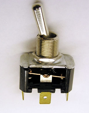
[img]cid:.0[/img]
Rivets have been used to assemble gazillions
of switches for decades. The designers of such
devices strive for rivets not to be the "weakest"
link in the chain of stresses on service life.
Let's look at the inner workings of a Carling toggle
(common to tens of thousands of Cessnas and certainly
thousands of OBAM aircraft). We observe TWO features
in the current carrying path that are more vulnerable
to wear-out or environmental failure. One is the
contacts. Resistance across the contacts is a function
of spring pressure and contact surface condition.
Resistance across the pivot-saddle is also a function
of spring force and surface condition . . . but at least
it gets "scrubbed" each operating cycle. Contacts just
get "hammered". Contacts also benefit from the cleansing
effects of electrical arcing to burn away products of
corrosion.
When installed with some attention to stresses on riveted
terminals, one can expect failure of the low-pressure,
moving-components to precede failure of the rivets by
perhaps an order of magnitude of service life.
Rivets in the switches are used in tension and they
join a stack of materials that includes a plastic.
Rivets in sheet metal are used in sheer. Further, if
properly drilled and set, they swell up in the hole to
form a metal-to-metal, gas tight fit . . . not unlike
the gas-tight fit of wires properly mashed in the
barrel of a terminal.
Riveted doublers to reduce sheet current density
around a high-current ground to airframe is probably
not a 'bad' idea . . . but if there are concerns
for getting a good ground in a thin-metal assembly,
perhaps going around it entirely with a bundle of
copper "cat-hairs" is a 'better' idea.
Bob . . .
| | - The Matronics AeroElectric-List Email Forum - | | | Use the List Feature Navigator to browse the many List utilities available such as the Email Subscriptions page, Archive Search & Download, 7-Day Browse, Chat, FAQ, Photoshare, and much more:
http://www.matronics.com/Navigator?AeroElectric-List |
|
| Description: |
|
| Filesize: |
55.32 KB |
| Viewed: |
11093 Time(s) |
|
|
|
| Back to top |
|
|
Louie928
Joined: 15 Nov 2009
Posts: 32
Location: Mosier, OR USA
|
| Posted: Fri Jul 22, 2011 9:01 am Post subject: Re: Airframe ground connection |
|
|
| Neal.George(at)hurlburt.a wrote: | The switches that we've seen fail at riveted joints didn't fail because
of the rivets, per se. They failed because rivets were used to join
grossly dissimilar materials - Bakelite/plastic sandwiched between metal
tabs - AND the leads were not supported adequately. In service,
movement of the wire leads relative to the switch body flexed the
terminal tabs, eventually loosening the riveted joint. As the riveted
joint works and loosens, the gas-tight electrical connection is
compromised. The less-than-ideal electrical connection introduces
electrical resistance which manifests as heat. The heat further damages
the loose rivet/plastic/copper interface thru corrosion and differential
thermal expansion rates, and a destructive cycle of rising resistance,
higher heat and accelerated damage results until the Bakelite cooks and
crumbles or the copper bits inside anneal and deform to the point that
the actuator can't move the rocker far enough to make/break the
connection.
Neal
| Quote: | Rivets do not make very good electrical connections unless there are
many of them in parallel (electrically). Certain brands of switches are
|
prone to fail because they use rivets to carry the current.
Joe Gores
| Quote: | > Something like 1/8" aluminum 2" or 3" in diameter riveted with, say 8
#4 rivets, to the underlying thin aluminum or galvanized steel to
|
distribute the current? |
You make a valid point regarding the riveted connectors on the switches. I've come across the exact problem you describe in my work. It can lead to intermittent problems before identification of the actual trouble spot. I bought all my switches from B&C and was dismayed to see they have the riveted connection to the push on spade connector. It takes little effort to move the connector under the rivet. These have apparently been used in a lot of airplanes over a long time so maybe no problems have surfaced. I'll need to be sure I have the wires well supported near the switch with no strain on the riveted connector.
Yes, distribute the current over a wider contact area of the thin aluminum, or steel. A simple bolted connection to 0.032" aluminum or the 0.018" galvanized steel firewall has a ridiculously small cross sectional area for the current to pass through. If it was wire it would be a very small CMA, like a fuse link. True, it is a short distance and the voltage drop won't be a lot. Heat will be generated which can contribute to problems down the road. If the bolted connection can be made through a thicker piece of material of 2 or 3 square inches area, and that thicker piece electrically connected to the thinner piece, the current will be distributed out to a much larger area of the thin metal and the current density won't be so high.
| | - The Matronics AeroElectric-List Email Forum - | | | Use the List Feature Navigator to browse the many List utilities available such as the Email Subscriptions page, Archive Search & Download, 7-Day Browse, Chat, FAQ, Photoshare, and much more:
http://www.matronics.com/Navigator?AeroElectric-List |
|
_________________
Louis W. Ott
601XL-B Corvair |
|
| Back to top |
|
|
nuckolls.bob(at)aeroelect
Guest
|
| Posted: Fri Jul 22, 2011 10:30 am Post subject: Airframe ground connection |
|
|
It takes little effort to move the connector under the rivet. These

have apparently been used in a lot of airplanes over a long time so

maybe no problems have surfaced. I'll need to be sure I have the

wires well supported near the switch with no strain on the riveted connector.


    Good practice . . . whether the terminals are riveted

    or not.


Yes, distribute the current over a wider contact area of the thin

aluminum, or steel. A simple bolted connection to 0.032" aluminum or

the 0.018" galvanized steel firewall has a ridiculously small cross

sectional area for the current to pass through.


    If you study the three sheets of Figure Z-15 found

    at http://www.aeroelectric.com/PPS/Adobe_Architecture_Pdfs/

    You will see a directed effort to minimize the use of airframe

    for any ground return currents.


If it was wire it would be a very small CMA, like a fuse link. True,

it is a short distance and the voltage drop won't be a lot. Heat will

be generated which can contribute to problems down the road. If the

bolted connection can be made through a thicker piece of material of

2 or 3 square inches area, and that thicker piece electrically

connected to the thinner piece, the current will be distributed out

to a much larger area of the thin metal and the current density won't

be so high.


    Assume a firewall ground feed-through stud is the

    central, single-point ground. Assume further that only

    a limited number of low-current remotely mounted accessories

    enjoy local airframe grounds, then current density and bonding

    issues go away. The firewall sheet carries a small percentage

    of the total system currents and never cranking current.

   Bob . . .
| | - The Matronics AeroElectric-List Email Forum - | | | Use the List Feature Navigator to browse the many List utilities available such as the Email Subscriptions page, Archive Search & Download, 7-Day Browse, Chat, FAQ, Photoshare, and much more:
http://www.matronics.com/Navigator?AeroElectric-List |
|
|
|
| Back to top |
|
|
Louie928
Joined: 15 Nov 2009
Posts: 32
Location: Mosier, OR USA
|
| Posted: Fri Jul 22, 2011 11:14 am Post subject: Re: Airframe ground connection |
|
|
Thanks very much for helping clear this up.
| | - The Matronics AeroElectric-List Email Forum - | | | Use the List Feature Navigator to browse the many List utilities available such as the Email Subscriptions page, Archive Search & Download, 7-Day Browse, Chat, FAQ, Photoshare, and much more:
http://www.matronics.com/Navigator?AeroElectric-List |
|
_________________
Louis W. Ott
601XL-B Corvair |
|
| Back to top |
|
|
user9253
Joined: 28 Mar 2008
Posts: 1975
Location: Riley TWP Michigan
|
| Posted: Sat Jul 23, 2011 5:28 am Post subject: Re: Airframe ground connection |
|
|
Neal,
That is very well put and explained. I agree with everything that you said. I wish that I could write that well.
Joe
Do not archive
| Quote: | The switches that we've seen fail at riveted joints didn't fail because
of the rivets, per se. They failed because rivets were used to join
grossly dissimilar materials - Bakelite/plastic sandwiched between metal
tabs - AND the leads were not supported adequately. In service,
movement of the wire leads relative to the switch body flexed the
terminal tabs, eventually loosening the riveted joint. As the riveted
joint works and loosens, the gas-tight electrical connection is
compromised. The less-than-ideal electrical connection introduces
electrical resistance which manifests as heat. The heat further damages
the loose rivet/plastic/copper interface thru corrosion and differential
thermal expansion rates, and a destructive cycle of rising resistance,
higher heat and accelerated damage results until the Bakelite cooks and
crumbles or the copper bits inside anneal and deform to the point that
the actuator can't move the rocker far enough to make/break the
connection.
Neal |
| | - The Matronics AeroElectric-List Email Forum - | | | Use the List Feature Navigator to browse the many List utilities available such as the Email Subscriptions page, Archive Search & Download, 7-Day Browse, Chat, FAQ, Photoshare, and much more:
http://www.matronics.com/Navigator?AeroElectric-List |
|
_________________
Joe Gores |
|
| Back to top |
|
|
n8zg(at)mediacombb.net
Guest
|
| Posted: Sat Jul 23, 2011 6:53 am Post subject: Airframe ground connection |
|
|
Thanks Joe -


Bob's an exceptional teacher, and I'm a poor student, but I'm trying...


--
| | - The Matronics AeroElectric-List Email Forum - | | | Use the List Feature Navigator to browse the many List utilities available such as the Email Subscriptions page, Archive Search & Download, 7-Day Browse, Chat, FAQ, Photoshare, and much more:
http://www.matronics.com/Navigator?AeroElectric-List |
|
|
|
| Back to top |
|
|
|
|
You cannot post new topics in this forum
You cannot reply to topics in this forum
You cannot edit your posts in this forum
You cannot delete your posts in this forum
You cannot vote in polls in this forum
You cannot attach files in this forum
You can download files in this forum
|
Powered by phpBB © 2001, 2005 phpBB Group
|

