 |
Matronics Email Lists
Web Forum Interface to the Matronics Email Lists
|
| View previous topic :: View next topic |
| Author |
Message |
user9253
Joined: 28 Mar 2008
Posts: 1961
Location: Riley TWP Michigan
|
 Posted: Sat Nov 26, 2011 9:21 am Post subject: Re: PTT Y adapter for RST intercom Posted: Sat Nov 26, 2011 9:21 am Post subject: Re: PTT Y adapter for RST intercom |
 |
|
Different manufacturers could have various names for their products.  To me, a breadboard has spring loaded sockets to plug parts into.  A perforated board is what I had in mind, similar to the Radio Shack one that you referenced. Although soldered wires on the bottom of the perf board do not look good compared to a printed circuit board, it is a quick and easy way to make a circuit.  But nobody is going to see it anyway.  The important thing is that the project is mechanically and electrically sound.

  There are also ready-made generic printed circuit boards that may or may not have traces suitable for mounting relays. Digikey sells perforated board, i.e, 3396K-ND, and V2018-ND.  See http://media.digikey.com/pdf/Data%20Sheets/Vector%20PDFs/Vectorbord%20Circbord.pdf

It appears that V2018-ND has strips of copper on the back side for soldering parts and wires that are located on the top side.  Perhaps someone who has experience with these boards will comment.  If suitable, this type of board will make a nice looking project.

  The wiring diagram that you attached looks like one that might be printed on the side of a relay.  It is a schematic to show how to connect wires.  A schematic does not necessarily show the actual physical layout.  I would be very surprised if both sets of contacts did not operate simultaneously.

Joe
| | - The Matronics AeroElectric-List Email Forum - | | | Use the List Feature Navigator to browse the many List utilities available such as the Email Subscriptions page, Archive Search & Download, 7-Day Browse, Chat, FAQ, Photoshare, and much more:
http://www.matronics.com/Navigator?AeroElectric-List |
|
_________________
Joe Gores |
|
| Back to top |
|
 |
messydeer
Joined: 13 Feb 2006
Posts: 214
Location: Bellingham, WA
|
| Posted: Sat Nov 26, 2011 9:53 am Post subject: Re: PTT Y adapter for RST intercom |
|
|
Yes, I just saw those boards at digikey. Of the two you mentioned, one is insulated, no plated holes. The other says 'continuous bus', which may not be what I need. At least I don't understand it. There's also another on the circbord.pdf link, #8029, which has plated holes. If I used the insulated non-plated one, soldering the terminals from the backside would hold the relay to the board in tension. With the plated one, I'd also have the terminals soldered directly to the plated board. Would the non-plated board connection be strong enough?
| | - The Matronics AeroElectric-List Email Forum - | | | Use the List Feature Navigator to browse the many List utilities available such as the Email Subscriptions page, Archive Search & Download, 7-Day Browse, Chat, FAQ, Photoshare, and much more:
http://www.matronics.com/Navigator?AeroElectric-List |
|
_________________
Dan |
|
| Back to top |
|
|
nuckolls.bob(at)aeroelect
Guest
|
| Posted: Sat Nov 26, 2011 10:20 am Post subject: PTT Y adapter for RST intercom |
|
|
At 11:21 AM 11/26/2011, you wrote:
| Quote: | --> AeroElectric-List message posted by: "user9253" <fran4sew(at)banyanol.com>
Different manufacturers could have various names for their products. To me, a breadboard has spring loaded sockets to plug parts into. A perforated board is what I had in mind, similar to the Radio Shack one that you referenced. Although soldered wires on the bottom of the perf board do not look good compared to a printed circuit board, it is a quick and easy way to make a circuit. But nobody is going to see it anyway. The important thing is that the project is mechanically and electrically sound. |
I've dug out the internal schematics for the RST
intercom and discovered that this is an INTERCOM
with no integration-friendly features for tying
it to one or more radios.
As an intercom, I'm mystified as to the installation
instructions that recommend opening the mic audio
leads to each mic along with the PTT signal. I.e.
a spring loaded, 2-pole, normally open push-button
DPST OFF-(ON).
If one adheres to this configuration, then it seems
that the value of an adjustable silencing
system (VOX, squelch, etc) is negated . . . the
existence of these switches in the mic audio leads
makes it a Push-to-Talk Intercom . . . not a VOX
intercom.
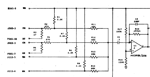
A study of the microphone input circuits to the
intercom shows that power to run the microphone's
electronics is provided internally to the intercom via
the 2.2K resistors tied to the mic leads from the
8v supply.
http://www.aeroelectric.com/Installation_Data/RST/RST-442.pdf
[img]cid:.0[/img]
However, there are PILOT MIC OUT and COPILOT MIC OUT
pins offered that "loop through" the intercom to
service any other audio need . . . ostensibly a
comm radio.
This presents a bit of a quandry for the system
integrator. To allow both mics of a two-pilot system
to access the radio, one needs to tie the two signals
together. Which puts 2 mic power sources in the
intercom arm wrestling with each other and the
third power source in the radio. Of course,
breaking the mic audio lines with the PTT switch
breaks one of those pathways while the system is
in use via the other pathway.
My suggestion:
No relays, no DPST, OFF-(ON) buttons.
Find connectors that mate with the pendant cables
coming out of the intercom (Molex or Mate-m-Lock?)
and set all that octopus of headset cables aside.
Wire microphones as always-hot signal leads to
their respective inputs on the intercom. Use the
VOX system to control background noise when not
speaking. Take the mic audio out leads from the
intercom to a SPDT, ON-ON switch so that audio
TO the DX-15 mic can be either pilot, co-pilot but
not both.
Wire as many single pole, SPST OFF-(ON) push
buttons as desired to the DX-15 PTT line. I'll
convert this description to a sketch as soon
as I get some other chores taken care of.
This is why the Dynon folks seemed to get stand-offish
when asked for advice. Without having both access
to internal working details of the intercom -AND-
time to offer what amounts to gratis, customized
system integration services, the guy didn't have
a clue as to what MIGHT work. Even my suggestion
has some risk that will have to shake out on the
bench: While talking on the radio, the 2.2K mic-power
bias resistors will be in parallel with what ever power
comes from the DX-15. I'm surprised that those
resistors are so large . . . their deleterious
effects on the DX-15 audio may well be minimal.
At the same time, it's possible that audio heard
over the intercom will take a jump in perceived
volume when transmitting. If that happens, we'll
need to go to plan-B.
In any case, I think a y-adapter only adds to
the snarl of snakes generally associated with
loose-in-the-cockpit intercom systems. It seems
prudent to simplify this wiring to the greatest
extent possible.
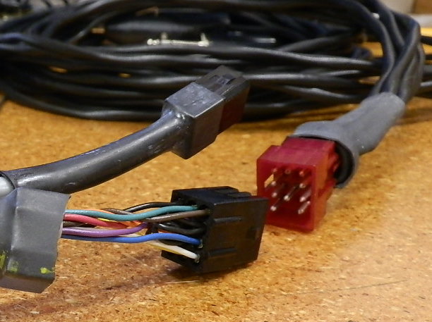
It would be helpful to know the style of connector
depicted in the RST drawing as "P101". A close-up photo
would be useful. I think Jim was fond of the
Molex mini nylon connectors back then but I
need to confirm this.
Bob . . .
| | - The Matronics AeroElectric-List Email Forum - | | | Use the List Feature Navigator to browse the many List utilities available such as the Email Subscriptions page, Archive Search & Download, 7-Day Browse, Chat, FAQ, Photoshare, and much more:
http://www.matronics.com/Navigator?AeroElectric-List |
|
| Description: |
|
| Filesize: |
50.54 KB |
| Viewed: |
13438 Time(s) |
|
|
|
| Back to top |
|
|
messydeer
Joined: 13 Feb 2006
Posts: 214
Location: Bellingham, WA
|
| Posted: Sat Nov 26, 2011 11:41 am Post subject: Re: PTT Y adapter for RST intercom |
|
|
| Quote: | As an intercom, I'm mystified as to the installation
instructions that recommend opening the mic audio
leads to each mic along with the PTT signal. I.e.
a spring loaded, 2-pole, normally open push-button
DPST OFF-(ON).
If one adheres to this configuration, then it seems
that the value of an adjustable silencing
system (VOX, squelch, etc) is negated . . . the
existence of these switches in the mic audio leads
makes it a Push-to-Talk Intercom . . . not a VOX
intercom. |
I thought this and all intercoms could function independently from the radio. Thought it would work even if there wasn't a radio connected. The vox and/or squelch of the intercom would work in a closed system between the two headsets.
I also thought placing these switches for the PTT's and mic's would not effect the intercom, since they are added between the intercom and the radio, not between the intercom and the headsets.
| Quote: | I'll
convert this description to a sketch as soon
as I get some other chores taken care of. |
This would be very helpful. I tore apart the intercom box a few days ago and plan to mount just the squelch, volume and pilot/all controls permanently to the panel. I'll cut off all the wires to the Molex connections to be able to put everything behind the panel. The only cables coming out into view would be those connecting directly with the handheld radio mounted at the corner of the instrument panel and side panel. This would be the power, mic/ptt, and headphone, along with the antenna cable.
| | - The Matronics AeroElectric-List Email Forum - | | | Use the List Feature Navigator to browse the many List utilities available such as the Email Subscriptions page, Archive Search & Download, 7-Day Browse, Chat, FAQ, Photoshare, and much more:
http://www.matronics.com/Navigator?AeroElectric-List |
|
| Description: |
|
| Filesize: |
75.96 KB |
| Viewed: |
13429 Time(s) |
|
_________________
Dan |
|
| Back to top |
|
|
user9253
Joined: 28 Mar 2008
Posts: 1961
Location: Riley TWP Michigan
|
| Posted: Sat Nov 26, 2011 11:50 am Post subject: Re: PTT Y adapter for RST intercom |
|
|
| Quote: | As an intercom, I'm mystified as to the installation instructions that recommend opening the mic audio leads to each mic along with the PTT signal. I.e. a spring loaded, 2-pole, normally open push-button DPST OFF-(ON).
If one adheres to this configuration, then it seems that the value of an adjustable silencing system (VOX, squelch, etc) is negated . . . the existence of these switches in the mic audio leads makes it a Push-to-Talk Intercom . . . not a VOX intercom. |
Bob,
The RST documentation makes it hard to understand whether it is referring to MIC audio input to the intercom or the audio output from the intercom. It took me awhile to realize that the questions that Dan was asking was about the output interface between the intercom and the hand-held radio. The headsets and MICs are plugged directly into the intercom. So as far as the intercom is concerned, the MICs are always connected.
The relay circuit that I suggested is an interface between the intercom and the hand-held radio. The relays do not open the headset MIC circuit to the intercom. The MICs are always hot. The relays choose which intercom audio output to connect to the hand-held radio.
| Quote: | | . . .set all that octopus of headset cables aside . . . . It seems prudent to simplify this wiring to the greatest extent possible. |
I agree with you. It reminds me of the rat's nest of wires behind my computer. 
Perhaps Dan will figure out a way to install it so that all wires are behind the panel except for the cable that plugs into the radio.
Joe
| | - The Matronics AeroElectric-List Email Forum - | | | Use the List Feature Navigator to browse the many List utilities available such as the Email Subscriptions page, Archive Search & Download, 7-Day Browse, Chat, FAQ, Photoshare, and much more:
http://www.matronics.com/Navigator?AeroElectric-List |
|
_________________
Joe Gores |
|
| Back to top |
|
|
user9253
Joined: 28 Mar 2008
Posts: 1961
Location: Riley TWP Michigan
|
| Posted: Sat Nov 26, 2011 12:50 pm Post subject: Re: PTT Y adapter for RST intercom |
|
|
Dan,

I just noticed that Digikey has a wiring diagram of the V2018-ND board.

http://www.vectorelect.com/Product/Circbord/Layout/8022%20Layout.pdf

The pins on a relay like Z768-ND will match the holes of the board.  Scratch a vertical line through the copper traces.  Mount the relay so that it straddles the scratched line.

Insert wires from the same side as the relay.

Solder the relays and wires to copper side of the board.

Joe
| | - The Matronics AeroElectric-List Email Forum - | | | Use the List Feature Navigator to browse the many List utilities available such as the Email Subscriptions page, Archive Search & Download, 7-Day Browse, Chat, FAQ, Photoshare, and much more:
http://www.matronics.com/Navigator?AeroElectric-List |
|
_________________
Joe Gores |
|
| Back to top |
|
|
nuckolls.bob(at)aeroelect
Guest
|
| Posted: Sun Nov 27, 2011 9:15 am Post subject: PTT Y adapter for RST intercom |
|
|
At 11:28 PM 11/25/2011, you wrote:
| Quote: |
Nice 
Hadn't thought about this before, but I think the PTT relay grounds
would go to a/c ground, and the other 4 would go to the radio jack
sleeve, right?
I also looked around Digikey.com for the relays. It was hard to
match the relays with sockets that are sold separately. I'm browsing
through Ebay, which may have something.
|
This relay . . .
http://search.digikey.com/us/en/products/G5V-2-DC12/Z768-ND/87821
is suited to the task and fits in this socket
http://search.digikey.com/us/en/products/4-1571552-2/4-1571552-2-ND/2258924
Bob . . .
| | - The Matronics AeroElectric-List Email Forum - | | | Use the List Feature Navigator to browse the many List utilities available such as the Email Subscriptions page, Archive Search & Download, 7-Day Browse, Chat, FAQ, Photoshare, and much more:
http://www.matronics.com/Navigator?AeroElectric-List |
|
|
|
| Back to top |
|
|
messydeer
Joined: 13 Feb 2006
Posts: 214
Location: Bellingham, WA
|
| Posted: Sun Nov 27, 2011 9:43 am Post subject: Re: PTT Y adapter for RST intercom |
|
|
Thanks, Bob


I understand these relays can be soldered to a perfboard. Joe had mentioned this, and I sorta forgot about the socket. Is there an advantage in using a socket, or could the relay be just as easily soldered directly onto a perfboard? I'd only be getting two of them and they're real cheap, so cost isn't an issue.
| | - The Matronics AeroElectric-List Email Forum - | | | Use the List Feature Navigator to browse the many List utilities available such as the Email Subscriptions page, Archive Search & Download, 7-Day Browse, Chat, FAQ, Photoshare, and much more:
http://www.matronics.com/Navigator?AeroElectric-List |
|
_________________
Dan |
|
| Back to top |
|
|
user9253
Joined: 28 Mar 2008
Posts: 1961
Location: Riley TWP Michigan
|
| Posted: Sun Nov 27, 2011 9:48 am Post subject: Re: PTT Y adapter for RST intercom |
|
|
Attached is a schematic that I drew of a single relay interface between RST-442 & Com radio. Only one MIC can be connected to the radio at a time.  I do not know if having the co-pilot MIC always connected to the radio hurts anything.  What do you think?

Joe
| | - The Matronics AeroElectric-List Email Forum - | | | Use the List Feature Navigator to browse the many List utilities available such as the Email Subscriptions page, Archive Search & Download, 7-Day Browse, Chat, FAQ, Photoshare, and much more:
http://www.matronics.com/Navigator?AeroElectric-List |
|
| Description: |
|
| Filesize: |
5.44 KB |
| Viewed: |
13380 Time(s) |
|
_________________
Joe Gores |
|
| Back to top |
|
|
user9253
Joined: 28 Mar 2008
Posts: 1961
Location: Riley TWP Michigan
|
| Posted: Sun Nov 27, 2011 10:19 am Post subject: Re: PTT Y adapter for RST intercom |
|
|
| Quote: | | Is there an advantage in using a socket, or could the relay be just as easily soldered directly onto a perfboard? |
I think it is a matter of personal preference. A socket will make it easy to replace a defective relay. The relay can not be damaged by heat from soldering if it is plugged into a socket. Sometimes troubleshooting is made easier by unplugging a component from a socket. But I prefer to solder parts directly to a PC board without using a socket, especially if subject to harsh environmental conditions. Then I do not have to worry about a bad connection between the part and the socket.
Joe
| | - The Matronics AeroElectric-List Email Forum - | | | Use the List Feature Navigator to browse the many List utilities available such as the Email Subscriptions page, Archive Search & Download, 7-Day Browse, Chat, FAQ, Photoshare, and much more:
http://www.matronics.com/Navigator?AeroElectric-List |
|
_________________
Joe Gores |
|
| Back to top |
|
|
user9253
Joined: 28 Mar 2008
Posts: 1961
Location: Riley TWP Michigan
|
| Posted: Sun Nov 27, 2011 1:16 pm Post subject: Re: PTT Y adapter for RST intercom |
|
|
See attached picture that shows how a perf board with copper strips can be used to make a project without having to acid etch a copper clad PC board.  While not suitable for complex circuits, simple circuits can be crafted by adding jumpers to the component side of the board.

Joe
| | - The Matronics AeroElectric-List Email Forum - | | | Use the List Feature Navigator to browse the many List utilities available such as the Email Subscriptions page, Archive Search & Download, 7-Day Browse, Chat, FAQ, Photoshare, and much more:
http://www.matronics.com/Navigator?AeroElectric-List |
|
| Description: |
|
| Filesize: |
158.32 KB |
| Viewed: |
13354 Time(s) |

|
_________________
Joe Gores |
|
| Back to top |
|
|
nuckolls.bob(at)aeroelect
Guest
|
| Posted: Mon Nov 28, 2011 6:34 pm Post subject: PTT Y adapter for RST intercom |
|
|
At 03:16 PM 11/27/2011, you wrote:
| Quote: | --> AeroElectric-List message posted by: "user9253" <fran4sew(at)banyanol.com>
See attached picture that shows how a perf board with copper strips can be used to make a project without having to acid etch a copper clad PC board. While not suitable for complex circuits, simple circuits can be crafted by adding jumpers to the component side of the board. |
Another options to consider . . .
[img]cid:.0[/img]
You could lay out a board like that shown above (actually, the
layout is already done) and order them from Express PCB.
Minimum order yields 18 boards in 3 days for about $69.
This board would accept a solder-cup D-sub along one
edge and mate to 9-pin de-sub of your choice. The board
is supported at one end on the mating connector. The other
end with a screw and spacer. Alternatively, one could
downsize the d-sub connectors like I did here
http://www.aeroelectric.com/articles/macservo/macservo.html
. . . and finish off the installation with a simple, over-all
cover of heat shrink where the relay assembly is simply tied
to a wire bundle.
In this instance, I think I'd solder the relay to the board
as opposed to setting it in a socket. This process would
yield a very compact relay assembly with robust construction,
very low assembly time and stone simple (d-sub) interface
to your radio.
Bob . . .
| | - The Matronics AeroElectric-List Email Forum - | | | Use the List Feature Navigator to browse the many List utilities available such as the Email Subscriptions page, Archive Search & Download, 7-Day Browse, Chat, FAQ, Photoshare, and much more:
http://www.matronics.com/Navigator?AeroElectric-List |
|
| Description: |
|
| Filesize: |
68.23 KB |
| Viewed: |
13334 Time(s) |

|
|
|
| Back to top |
|
|
messydeer
Joined: 13 Feb 2006
Posts: 214
Location: Bellingham, WA
|
| Posted: Tue Nov 29, 2011 9:05 am Post subject: Re: PTT Y adapter for RST intercom |
|
|
Thanks, Bob and Joe
I've ordered the relay and continuous bus perfboard. I'll post some pics when I get it assembled.
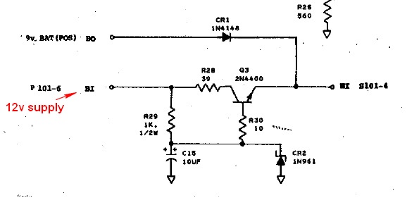
I also was wondering about the power supply. I'll wire the a/c 12v supply to the wire connected to the BI terminal on the intercom circuit board. There is also an option to add a 9v battery for backup, connected to the BO terminal. I have a 1.2 Ah 12v battery that is used for my EFIS backup supply and wonder if I could wire this to the BO terminal in place of the 9v. Would I need a resistor between my 12v backup battery and the BO terminal, to drop it down to 9v? If so, how do I figure the size?
How would I know the intercom is drawing current from the main 12v supply (BI) and not the backup (BO)? Even though the small 12v backup battery gets recharged by the main a/c 12v supply, seems I'd want the a/c 12v supply to provide power for the intercom.
| | - The Matronics AeroElectric-List Email Forum - | | | Use the List Feature Navigator to browse the many List utilities available such as the Email Subscriptions page, Archive Search & Download, 7-Day Browse, Chat, FAQ, Photoshare, and much more:
http://www.matronics.com/Navigator?AeroElectric-List |
|
| Description: |
|
| Filesize: |
23.33 KB |
| Viewed: |
13312 Time(s) |
|
_________________
Dan |
|
| Back to top |
|
|
|
|
You cannot post new topics in this forum
You cannot reply to topics in this forum
You cannot edit your posts in this forum
You cannot delete your posts in this forum
You cannot vote in polls in this forum
You cannot attach files in this forum
You can download files in this forum
|
Powered by phpBB © 2001, 2005 phpBB Group
|

