 |
Matronics Email Lists
Web Forum Interface to the Matronics Email Lists
|
| View previous topic :: View next topic |
| Author |
Message |
etienne.phillips(at)gmail
Guest
|
 Posted: Thu Feb 16, 2012 5:59 pm Post subject: Servo problem Posted: Thu Feb 16, 2012 5:59 pm Post subject: Servo problem |
 |
|
Hi All
Im hoping that an RF greybeard will be able to offer some advice
Ive built an elevator trim system for my aeroplane, using an RC servo mounted in the control surface, which is driven by a PIC18F microcontroller. This has worked flawlessly for 2 years.
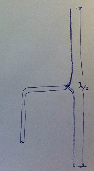
On the back of this success I built another identical one for a friend, and due to the difference in installation which Ill explain shortly, I am being plagued by a fault that I havent been able to solve. The instigator for this problem is the RF emitted by the COM antenna, which on my aircraft is between the undercarriage (taildragger), and on the friends is inside the vertical stabiliser. The design of the friends antenna is as follows:
[img]cid:image002.jpg(at)01CCECBE.AF74CAB0[/img]
The braiding of the coax is stretched out in one direction whist the core is stretched out in the other. Since its a fiberglass aeroplane, the antenna is bonded to the skin of the vertical stab, without worry of electrical problems.
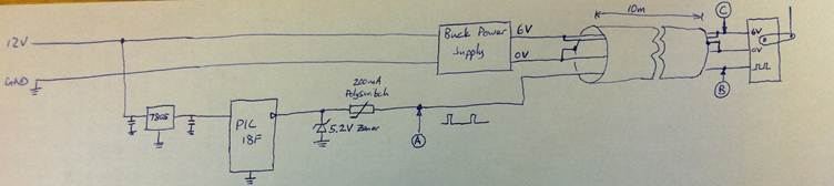
The design of the trim system is as follows:
[img]cid:image010.jpg(at)01CCECBE.AF74CAB0[/img]
Ships power is fed through a 7805 (with required smoothing caps) to the 18F4520, which generates the 1-2ms square pulse required by the servo. The output of the PIC is protected by a polyswitch and zener diode combo, resulting in a fairly low impedance output. Meanwhile, the power is fed into an off-the-shelf RC power converter, which has a 6V, 15Amp capable output. Signal and power is fed through a shielded 4-core tefzel wire to the back of the aeroplane where it breaks out into the connections required by the servo motor. The 6V power line is fed over two cores, whilst ground is connected via one core and the shield.
The problem: when transmitting on the radio at the low end of the airband spectrum 118Mhz, the servo goes bezerk. At 125MHz it twitches occasionally, but is mostly usable.
I took an oscilloscope out to the aeroplane, and tested at points A, B and C whilst both transmitting and not.
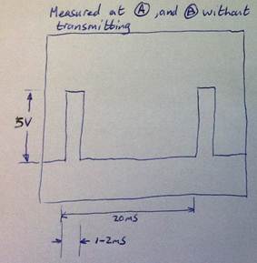
At A, the signal output by the PIC is clean, and unaffected by the noise induced by transmission. The same signal is measured at B whilst not transmitting:
[img]cid:image011.jpg(at)01CCECBE.AF74CAB0[/img]
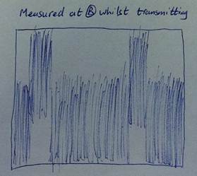
When transmitting, however, the signal at B becomes completely degraded:
[img]cid:image012.jpg(at)01CCECBE.AF74CAB0[/img]
The amplitude of the noise is approximately 5Vp-p, superimposed on the desired 5Vp-p signal. No wonder the servo doesnt know whats going on!
The power line is completely clean on both ends of the wire, at C and the output to the power converter.
I am aware that the suitability of using an RC servo in a real aircraft is a concern, but as has been proven in my aeroplane, mechanically and aerodynamically the system works well, providing enough authority to trim adequately without being so powerful that it cannot be over-ridden using excessive force. The microcontroller code and electrical design of the board has also proven to be reliable, and the installation in my aeroplane has been robust and able to withstand the noise generated from the com radio, although the distance to the antenna is much greater (not closer than 2 meters). We both have the same radio, an MGL VHF-10.
In the knowledgeable opinions of those who have RF experience, will I be able to implement a filter at the servo end of the wire to filter out the 120MHz-odd signal whilst retaining the integrity of the pulse? I tried using a 1uF electrolytic cap as a filter (this was the only cap I had on-hand, as the aeroplane is a 90min drive out of town), which had no effect on the noise, and only degraded the underlying signal further. I know that the cap isnt rated at high frequencies, so I only include it as an anecdote. Im concerned about putting a ceramic cap in a EM field will this not act as an antenna and make the problem worse?
Any advice would be appreciated!
Thanks,
Etienne
| | - The Matronics AeroElectric-List Email Forum - | | | Use the List Feature Navigator to browse the many List utilities available such as the Email Subscriptions page, Archive Search & Download, 7-Day Browse, Chat, FAQ, Photoshare, and much more:
http://www.matronics.com/Navigator?AeroElectric-List |
|
| Description: |
|
| Filesize: |
15.96 KB |
| Viewed: |
27437 Time(s) |
|
| Description: |
|
| Filesize: |
9.62 KB |
| Viewed: |
27437 Time(s) |
|
| Description: |
|
| Filesize: |
13.68 KB |
| Viewed: |
27437 Time(s) |
|
| Description: |
|
| Filesize: |
10.52 KB |
| Viewed: |
27437 Time(s) |
|
|
|
| Back to top |
|
 |
nuckolls.bob(at)aeroelect
Guest
|
| Posted: Thu Feb 16, 2012 7:27 pm Post subject: Servo problem |
|
|
In the knowledgeable opinions of those who have
RF experience, will I be able to implement a
filter at the servo end of the wire to filter out
the 120MHz-odd signal whilst retaining the integrity of the pulse?
Absolutely. The variable position pulse is about a
half light-year away from the antagonistic signal . . .
well . . . maybe not light years but certainly separated
by many decades of RF spectrum separation.
We're talking sub killohertz versus 100 mHz or about
5 decades. A filter crafted to attenuate 100 mHz is
totally transparent to your signal-of-interest.
Based on your explorations and observations, it seems
likely that the RC servo is having problems with the
stronger RF field. RF, like all electro-magnetic
propagation attenuates based on the "square-law".
If you double the distance between emitting and
detecting devices, effects on the detector are
reduced to 1/4th of the original. That's a FAR FIELD
condition where there are no, distortions to the
field as it crosses the gap.
We know that the closer proximity of antenna
to servo can offer a profound increase in potential
interference. You also have NEAR-FIELD effects airplane
and wiring geometry. Far-field effects are only slightly
affected by frequency, near-field effects include
the effects of standing waves on airframe and wiring
which can be VERY sensitive to changes of frequency
for the antagonist signal. I can show you data
gathered in the hell-hole of a Hawker 800 were standing
waves generated by a poorly designed antenna system
would offer 1000:1 variations in interfering signal
while standing in one place and moving a probe around
within arm's reach. Further, the effects varied profoundly
from airplane to airplane.
I tried using a 1uF electrolytic cap as a
filter (this was the only cap I had on-hand, as
the aeroplane is a 90min drive out of town),
which had no effect on the noise, and only
degraded the underlying signal further. I know
that the cap isnt rated at high frequencies, so
I only include it as an anecdote. Im concerned
about putting a ceramic cap in a EM field will
this not act as an antenna and make the problem worse?
Ceramic capacitors are not counter-indicated
for this task. The few R/C servos I've played
with all had plastic cases and ZERO provisions
for managing electro-magnetic compatibility.
Without taking your servos to the lab and doing
the full DO-160 work-up, I cannot offer anything
like an elegant, optimized solution.
I will suggest some sledge-and-crowbar techniques
with a high probability of success.
I would "wrap" the servo in copper tape to craft
a metallic enclosure. I would fabricate two, pi-
section filters on the outside surface right where
the wires come out of the actuator. The actuator
ground would tie to the outside copper shell.
Two capacitors for each of the two filters would also
solder directly to the shell. The schematic would
look something like this.
http://tinyurl.com/6vekr2o
The actual parts values are exceedingly un-critical.
Components spanning perhaps 1000:1 ratios of
value would do the job without degrading the
command signal. The elegant components are
driven more by physical characteristics that
lend themselves to "spider-webbing" onto the
side of a thin walled, copper box.
If you could send me one of the servos along with
a picture of the installed servo showing where
the envelope could grow some warts without hitting
anything in the airplane, I can pretty quickly
accomplish the proposed modification. I would
take pictures of the process and provide a bill
of materials.
If the mod proves successful, I'll publish the
solution to the AEC website. If there's a demand
for these filters, we could do an etched circuit
board layout and fab a Mk II filter from surface
mount components. More elegant yet.
If you'd like to take a whack at a DIY solution,
I'd start with inductors on the order of 1 uHy
and capacitors on the order of 1000 pF. And yes,
they could be ceramic disks . . . just keep the
leads short.
By the way, ferrite beads on the wires are exceedingly
unlikely to fix this. Benefits of ferrites as
over-the-bundle solutions to EMC problems are exceedingly
over-rated. Any device destined to fly on a TC aircraft
would have run the DO-160 gauntlet and enjoys necessary
filters INSIDE. Any installation instructions that
call for external fixes or prophylactics to be added
as part of the installation process says the designer
has not done their homework.
Bob . . .
| | - The Matronics AeroElectric-List Email Forum - | | | Use the List Feature Navigator to browse the many List utilities available such as the Email Subscriptions page, Archive Search & Download, 7-Day Browse, Chat, FAQ, Photoshare, and much more:
http://www.matronics.com/Navigator?AeroElectric-List |
|
|
|
| Back to top |
|
|
etienne.phillips(at)gmail
Guest
|
| Posted: Mon Feb 20, 2012 9:39 am Post subject: Servo problem |
|
|
Hi Bob
Thanks for the advice, and the solution! I installed a Pi filter only on the signal line, but with components of 100pF and 10uH, as that's what was available. The power line didn't seem to be affected by the noise, so I decided to try just the signal line first, then add the power line filter if required.
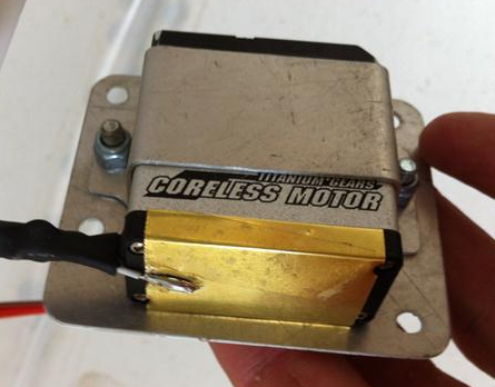
I also added a shield to the bottom of the servo using brass shimstock (I figured it was almost the same as copper foil, but somewhat more available - however not quite as solderable).
[img]cid:image005.png(at)01CCF006.F801CF80[/img]
The soldering in the photo doesn't appear to have flowed and stuck properly, but I gave it a good tug and it didn't come loose, so I just attributed it to the brass. The filter is inside the heatshrink, well supported from vibration.
The servo is a Turnigy HV-767 (http://www.hobbyking.com/hobbyking/store/uh_viewItem.asp?idProduct=9983) - a 31kg.cm monster, but is still the standard size, which makes it small enough to fit comfortably in the elevator. The casing is aluminium, save for the plastic cap at the bottom where all the electronics sits. At $60 a pop, it's a fairly cheap alternative to the Ray Allen servo, and capable of being used for much more than just trim.
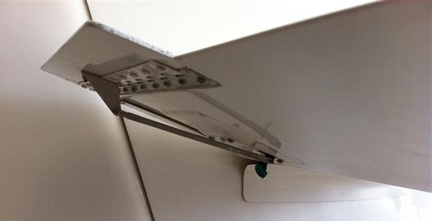
The installation space is really tight, which meant that the filter had to sit outside the cavity, which limited my options for shielding hence the small strip over the bottom of the servo.
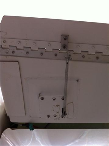
[img]cid:image002.png(at)01CCF006.95F456F0[/img]
[img]cid:image006.png(at)01CCF006.F801CF80[/img]
After adding the filter and the shielding, the signal going into the servo is absolutely clean, without a shred of noise visible on the signal line. The servo doesn't even notice the radio transmission now, so I'm very relieved!
This is what the controller up front looks like:
[img]cid:image007.png(at)01CCF006.F801CF80[/img]
There is also a stick-mounted rocker switch for easy trimming. The knob on the face allows you to save a position (such as the take-off trim), and return to it with a single click.
My current project is the autopilot side of this, which reads data in from an Efis and does the required maths, sending the resulting trimmer position to the trim controller over an RS-485 link (this is why I went for such big servos). So far, altitude hold works, whilst bank and yaw are waiting to be flight tested.
Thanks also for the offer of crafting a more elegant solution. Since the filter is so simple to fabricate, and seems to work in this really abusive environment, I wonder if it's even necessary
? With plugs and attachments it'll probably be unwieldy to install in such a small spot.
Once again, thanks!
Etienne
| | - The Matronics AeroElectric-List Email Forum - | | | Use the List Feature Navigator to browse the many List utilities available such as the Email Subscriptions page, Archive Search & Download, 7-Day Browse, Chat, FAQ, Photoshare, and much more:
http://www.matronics.com/Navigator?AeroElectric-List |
|
| Description: |
|
| Filesize: |
180.56 KB |
| Viewed: |
27424 Time(s) |
|
| Description: |
|
| Filesize: |
135.11 KB |
| Viewed: |
27424 Time(s) |
|
| Description: |
|
| Filesize: |
103.75 KB |
| Viewed: |
27424 Time(s) |
|
| Description: |
|
| Filesize: |
49.65 KB |
| Viewed: |
27424 Time(s) |

|
|
|
| Back to top |
|
|
jonlaury
Joined: 06 Nov 2006
Posts: 336
|
| Posted: Mon Feb 20, 2012 10:16 pm Post subject: Re: Servo problem |
|
|
Bob,
This sounds like a similar situation that I'm encountering with an EyeBeam that uses capacitance for on/off and for dimming. It's housed in a small ceiling mounted enclosure with my cabin speaker.
Everytime I key the mike, the EB flashes uncontrollably and the on/off and dimming functions go inop. The only way to stop it is to pull the fuse.
Wishful thinking had me try ferrite clamps over the speaker wires or the EB twisted pair shielded cable to no effect. But you knew that  . .
Would the solution you devised for Etienne be germane to solving my problem?
Not sure how I would implement the copper shield as 1/2 of the EB is enclosed with the speaker and 1/2 is exposed to the cabin.
Thanks,
John
I really like the EB and the small tidy console that houses the speaker so I hope that I don't have to give it up to use a less EM/RF sensitive source of light.
| | - The Matronics AeroElectric-List Email Forum - | | | Use the List Feature Navigator to browse the many List utilities available such as the Email Subscriptions page, Archive Search & Download, 7-Day Browse, Chat, FAQ, Photoshare, and much more:
http://www.matronics.com/Navigator?AeroElectric-List |
|
|
|
| Back to top |
|
|
enginerdy(at)gmail.com
Guest
|
| Posted: Mon Feb 20, 2012 11:03 pm Post subject: Servo problem |
|
|
I'm sorry your ferrites didn't work.
Did you ever try to see if keying the mic without the comm radio on prevents the issue?
On Feb 21, 2012, at 12:16 AM, jonlaury wrote:
| Quote: |
Bob,

This sounds like a similar situation that I'm encountering with an EyeBeam that uses capacitance for on/off and for dimming. It's housed in a small ceiling mounted enclosure with my cabin speaker.

Everytime I key the mike, the EB flashes uncontrollably and the on/off and dimming functions go inop. The only way to stop it is to pull the fuse.

Wishful thinking had me try ferrite clamps over the speaker wires or the EB twisted pair shielded cable to no effect. But you knew that .


Would the solution you devised for Etienne be germane to solving my problem?

Not sure how I would implement the copper shield as 1/2 of the EB is enclosed with the speaker and 1/2 is exposed to the cabin.


Thanks,

John


I really like the EB and the small tidy console that houses the speaker so I hope that I don't have to give it up to use a less EM/RF sensitive source of light.
Read this topic online here:
http://forums.matronics.com/viewtopic.php?p=366804#366804
|
| | - The Matronics AeroElectric-List Email Forum - | | | Use the List Feature Navigator to browse the many List utilities available such as the Email Subscriptions page, Archive Search & Download, 7-Day Browse, Chat, FAQ, Photoshare, and much more:
http://www.matronics.com/Navigator?AeroElectric-List |
|
|
|
| Back to top |
|
|
nuckolls.bob(at)aeroelect
Guest
|
| Posted: Tue Feb 21, 2012 11:39 am Post subject: Servo problem |
|
|
At 12:16 AM 2/21/2012, you wrote:
| Quote: |
Bob,
This sounds like a similar situation that I'm encountering with an
EyeBeam that uses capacitance for on/off and for dimming. It's
housed in a small ceiling mounted enclosure with my cabin speaker.
Everytime I key the mike, the EB flashes uncontrollably and the
on/off and dimming functions go inop. The only way to stop it is to
pull the fuse.
Wishful thinking had me try ferrite clamps over the speaker wires or
the EB twisted pair shielded cable to no effect. But you knew that .
Would the solution you devised for Etienne be germane to solving my problem?
|
Probably not. Touch-buttons that sense body capacity
can be really twitchy in the presence of strong RF.
Can you send me a wiring diagram for your lighting
control system? I must admit that I'm not optimistic
but we can try. Need to see the installation manual
and wiring.
Bob . . .
| | - The Matronics AeroElectric-List Email Forum - | | | Use the List Feature Navigator to browse the many List utilities available such as the Email Subscriptions page, Archive Search & Download, 7-Day Browse, Chat, FAQ, Photoshare, and much more:
http://www.matronics.com/Navigator?AeroElectric-List |
|
|
|
| Back to top |
|
|
jonlaury
Joined: 06 Nov 2006
Posts: 336
|
| Posted: Tue Feb 21, 2012 2:44 pm Post subject: Re: Servo problem |
|
|
Daniel,

No worries re the ferrites. It was easy and worth a shot. Thanks for trying. With the com off there's no problem with the EB. There's a 15' parallel run of speaker and EB wiring  and that's where the problem is. When I run non-parallel wiring to power the EB, the problem disappears. Soo...see below.


Bob,

Thank you for your willingness to give it a go, but I've decided that the simplest fix is to re-route the wires to the EB. I didn't want to do that because it means pulling out some nice upholstery work to get 2 x 22 ga wires underneath it. But I know from experimentation that it will work.

That's going to be the best use of both yours and my time.


Cheers,

John
| | - The Matronics AeroElectric-List Email Forum - | | | Use the List Feature Navigator to browse the many List utilities available such as the Email Subscriptions page, Archive Search & Download, 7-Day Browse, Chat, FAQ, Photoshare, and much more:
http://www.matronics.com/Navigator?AeroElectric-List |
|
|
|
| Back to top |
|
|
nuckolls.bob(at)aeroelect
Guest
|
| Posted: Wed Feb 22, 2012 7:12 am Post subject: Servo problem |
|
|
At 11:36 AM 2/20/2012, you wrote:
Hi Bob
Thanks for the advice, and the solution! I
installed a Pi filter only on the signal line,
but with components of 100pF and 10uH, as that's
what was available. The power line didn't seem to
be affected by the noise, so I decided to try
just the signal line first, then add the power line filter if required.
Good show.
<snip>
Thanks also for the offer of crafting a more
elegant solution. Since the filter is so simple
to fabricate, and seems to work in this really
abusive environment, I wonder if it's even
necessary
? With plugs and attachments it'll
probably be unwieldy to install in such a small spot.
It wouldn't necessarily have any plugs, only
attach pads for wires. I envision an ECB perhaps
0.7" x 1.0" that would accommodate surface mount
components on one side leaving the other flat.
Holes in the corners would let you solder-thru
to attach the board directly to the outside copper
foil on the actuator while simultaneously grounding
the filter to the foil.
Wires would come off each end. They would, of course,
be strain relieved with adhesive or perhaps tied
down with another layer of copper tape over the whole
filter/wiring installation.
Pretty small and low profile.
In any case, it looks like your dragon has been
held at bay.
Bob . . .
| | - The Matronics AeroElectric-List Email Forum - | | | Use the List Feature Navigator to browse the many List utilities available such as the Email Subscriptions page, Archive Search & Download, 7-Day Browse, Chat, FAQ, Photoshare, and much more:
http://www.matronics.com/Navigator?AeroElectric-List |
|
|
|
| Back to top |
|
|
jonlaury
Joined: 06 Nov 2006
Posts: 336
|
| Posted: Thu Feb 23, 2012 2:25 pm Post subject: Re: Servo problem |
|
|
Bob,


Before I go ripping into my headliner, I put the question to the Aveo engineers about the interference that the EyeBeam was getting from somewhere.

They suggested this:


http://www.lineagepower.com/oem/pdf/FLT012A0Z.pdf


If you think this is the right track, does it go on the antagonist wiring or the EB wiring?


Cheers,

John
| | - The Matronics AeroElectric-List Email Forum - | | | Use the List Feature Navigator to browse the many List utilities available such as the Email Subscriptions page, Archive Search & Download, 7-Day Browse, Chat, FAQ, Photoshare, and much more:
http://www.matronics.com/Navigator?AeroElectric-List |
|
|
|
| Back to top |
|
|
nuckolls.bob(at)aeroelect
Guest
|
| Posted: Thu Feb 23, 2012 3:00 pm Post subject: Servo problem |
|
|
At 04:25 PM 2/23/2012, you wrote:
| Quote: |
Bob,
Before I go ripping into my headliner, I put the question to the
Aveo engineers about the interference that the EyeBeam was getting
from somewhere.
They suggested this:
http://www.lineagepower.com/oem/pdf/FLT012A0Z.pdf
If you think this is the right track, does it go on the antagonist
wiring or the EB wiring?
|
I looked up the product and found the wiring
diagrams. THAT filter is like killing fleas
with a 12 gauge . . .
How many of these devices are installed on your
airplane?
Bob . . .
| | - The Matronics AeroElectric-List Email Forum - | | | Use the List Feature Navigator to browse the many List utilities available such as the Email Subscriptions page, Archive Search & Download, 7-Day Browse, Chat, FAQ, Photoshare, and much more:
http://www.matronics.com/Navigator?AeroElectric-List |
|
|
|
| Back to top |
|
|
Eric M. Jones
Joined: 10 Jan 2006
Posts: 565
Location: Massachusetts
|
| Posted: Fri Feb 24, 2012 7:39 am Post subject: Re: T-antennae |
|
|
Etienne drew a T-antenna on his discussion of the servo problem. This incluced stripping back the insulation on a coax, separating the shield and core, and stretching out each to form a Tee.


Clever. Actually too-clever-by-half. Would that it could be so easy! The problem lies in the termination, since the core and shield do not share the signal. In fact neither the core nor the shield even CARRY the signal.


See: periheliondesign.com/downloads/Dabbling%20with%20electricity.pdf


Then grab your SWR meter and Google any of the ham radio sites and see how to design a T-antenna.


Might it work the way Etienne shows? A little probably, but let's do it right.
| | - The Matronics AeroElectric-List Email Forum - | | | Use the List Feature Navigator to browse the many List utilities available such as the Email Subscriptions page, Archive Search & Download, 7-Day Browse, Chat, FAQ, Photoshare, and much more:
http://www.matronics.com/Navigator?AeroElectric-List |
|
_________________
Eric M. Jones
www.PerihelionDesign.com
113 Brentwood Drive
Southbridge, MA 01550
(508) 764-2072
emjones(at)charter.net |
|
| Back to top |
|
|
nuckolls.bob(at)aeroelect
Guest
|
| Posted: Sat Feb 25, 2012 5:55 am Post subject: Servo problem |
|
|
I looked up the product and found the wiring
diagrams. THAT filter is like killing fleas
with a 12 gauge . . .
How many of these devices are installed on your
airplane? How hard is it to remove them for
service/modification? If filtering the two
power lines is a solution to be explored, then
the filter components are quite small and
can be assembled right to the back of the
device were the wires emerge.
I'm disappointed but not surprised that the
folks who designed/built/marketed these
into aircraft did not fully appreciate
the potential for strong RF fields. Mobile
transmitters in vehicles of all kinds are
very strong locally . . . and they travel
around with the vehicle. You don't just
pass one occasionally.
In my earliest days of gainful employment
I worked for several two-way radio companies.
It was not uncommon to do installations of
transmitters having power outputs of 60
watts. Back then, the vehicle's other
systems were out of the copper-steel-
Bakelite (CSB) era. Exceedingly robust with
respect to RFI. In the silicon-software-
glass (SSG) era, virtually every active
component of a vehicles systems and accessories
is a potential victim for upset by local
radio energy fields.
Talk to the engineers that suggested the
boss-hog filters and see if they'll send
me a couple of these lights to play with.
If they would send a schematic of their
internals, it would be helpful too.
I'll craft a "scab-on" filter which they
can recommend for folks such as yourself
and consider for inclusion INSIDE future
production. You can encourage them to
contact me directly.
Barring their direct interest and response,
we can put the filters on your lights.
I suspect you could simply cut the lead wires
at the back of the dismounted units.
Leave me 1" pigtails. I'll send them
back with some sort of connector so
that you can re-install them in your
airplane.
Bob . . .
| | - The Matronics AeroElectric-List Email Forum - | | | Use the List Feature Navigator to browse the many List utilities available such as the Email Subscriptions page, Archive Search & Download, 7-Day Browse, Chat, FAQ, Photoshare, and much more:
http://www.matronics.com/Navigator?AeroElectric-List |
|
|
|
| Back to top |
|
|
jonlaury
Joined: 06 Nov 2006
Posts: 336
|
| Posted: Sat Feb 25, 2012 8:15 am Post subject: Re: Servo problem |
|
|
Bob,

I sent the following out this morning. Please let me know if they bite.


And thank you once AGAIN (and again, and again...!) for your generous offer to craft a solution to the RF problem with the EyeBeam. Hearing from you that this can be solved with an add-on filter, gives me confidence to go ahead and finally install the structural belly panel (with its 60+ screws, and covering the EB wiring) and move on to firing this thing up!


Cheers,

John


I regularly read, monitor and contribute to the Aerolectric List, which is monitored by Bob Nuckolls, a long time consulting electrical engineer for Piper, Beech, Cessna, Lear, Hawker, etc.

He is immensely generous and helpful to the experimental aircraft community in designing electrical architectures for the large variety of experimental aircraft and missions and enjoys solving challenging problems.


I submitted my RF problem with the EB and here is his response. I hope you will take him up on his offer. The discussion started out because someone had an RF problem with a servo, hence, "Post subject: Servo problem" I responded by asking if the solution he crafted for the servo might be appropriate for the RF problem with my EB.


Contact him directly here: http://www.aeroelectric.com/bob.nuckolls/


(Bob's response)
| | - The Matronics AeroElectric-List Email Forum - | | | Use the List Feature Navigator to browse the many List utilities available such as the Email Subscriptions page, Archive Search & Download, 7-Day Browse, Chat, FAQ, Photoshare, and much more:
http://www.matronics.com/Navigator?AeroElectric-List |
|
|
|
| Back to top |
|
|
|
|
You cannot post new topics in this forum
You cannot reply to topics in this forum
You cannot edit your posts in this forum
You cannot delete your posts in this forum
You cannot vote in polls in this forum
You cannot attach files in this forum
You can download files in this forum
|
Powered by phpBB © 2001, 2005 phpBB Group
|

