 |
Matronics Email Lists
Web Forum Interface to the Matronics Email Lists
|
| View previous topic :: View next topic |
| Author |
Message |
rv8ch
Joined: 10 Jan 2006
Posts: 250
Location: Switzerland
|
 Posted: Sat Aug 04, 2012 12:28 pm Post subject: Starter contactor leaking voltage Posted: Sat Aug 04, 2012 12:28 pm Post subject: Starter contactor leaking voltage |
 |
|
Thanks Bob, Gents, for the feedback on this. I have done it the way the plans show, and you suggested, and put the starter contactor on the FW.
New question (yes, I'm building very slowly) - I have the Van's starter contactor (Part Number = ES 24021) and when I apply 12v to the battery connection, I get about 0.4v on the starter connection. Â This is before it is energized. Â When I apply the 12v to the 'S' terminal, I get the full 12v on the starter terminal.
Is it normal for some voltage to "leak" even when the device is "idle"? Â My battery contactors don't do this, and I don't have another starter contactor to test with.
Thanks,
Mickey  Â
[quote][b]
| | - The Matronics AeroElectric-List Email Forum - | | | Use the List Feature Navigator to browse the many List utilities available such as the Email Subscriptions page, Archive Search & Download, 7-Day Browse, Chat, FAQ, Photoshare, and much more:
http://www.matronics.com/Navigator?AeroElectric-List |
|
_________________
Mickey Coggins
http://www.rv8.ch/ |
|
| Back to top |
|
 |
user9253
Joined: 28 Mar 2008
Posts: 1975
Location: Riley TWP Michigan
|
| Posted: Sun Aug 05, 2012 4:18 am Post subject: Re: Starter contactor leaking voltage |
|
|
Theoretically there should be NO leakage through the starter contactor.  But the insulation used in the contactor is not perfect.  There could be some insignificant leakage.  Digital voltmeters have a very high input impedance which allows them to measure insignificant voltage.  Try shorting the output terminal to ground with your fingers of one hand while measuring the voltage.  Or use an old analog voltmeter which will give more meaningful measurements in this situation.  Or use a very small 12v test lamp, the type used for automotive instrument illumination.

  I do not think there is enough leakage to worry about.

Joe
| | - The Matronics AeroElectric-List Email Forum - | | | Use the List Feature Navigator to browse the many List utilities available such as the Email Subscriptions page, Archive Search & Download, 7-Day Browse, Chat, FAQ, Photoshare, and much more:
http://www.matronics.com/Navigator?AeroElectric-List |
|
_________________
Joe Gores |
|
| Back to top |
|
|
Eric M. Jones
Joined: 10 Jan 2006
Posts: 565
Location: Massachusetts
|
| Posted: Sun Aug 05, 2012 6:48 am Post subject: Re: Starter contactor leaking voltage |
|
|
repost


      As others have mentioned, the problem is in how you use your tools...like the voltmeter.


      Imagine that you have a voltmeter that is infinitely sensitive (infinite impedance). Now it will measure the battery voltage even thru an open switch. In fact, it will measure 500 volts between your belt buckle and your shoe laces. And the top of your hat will be 1000 volts higher than the soles of your New Balance sneakers. You can actually extract some tiny amount of power this way.


      So meter impedance is not a lack of quality in a meter, it is a necessary and useful characteristic of the measuring device. And in a solid state circuit (like a diode), there will almost always be a voltage on the output that is similar to the input voltage even when the meter is off. And in fact the "leakage voltage" will not be able to light even the tiniest LED...so ignore it.


      I once designed a Cmos circuit where somebody (okay, me...) forgot to add the power trace to the IC. Years later, an inquisitive technician, tracing an unrelated fault discovered it, but all the shipped product had worked just fine.


      So just don't make voltage measurements like this.


      See attached for a better way.


      --------
| | - The Matronics AeroElectric-List Email Forum - | | | Use the List Feature Navigator to browse the many List utilities available such as the Email Subscriptions page, Archive Search & Download, 7-Day Browse, Chat, FAQ, Photoshare, and much more:
http://www.matronics.com/Navigator?AeroElectric-List |
|
| Description: |
|

Download |
| Filename: |
Diode test.pdf |
| Filesize: |
79.23 KB |
| Downloaded: |
549 Time(s) |
_________________
Eric M. Jones
www.PerihelionDesign.com
113 Brentwood Drive
Southbridge, MA 01550
(508) 764-2072
emjones(at)charter.net |
|
| Back to top |
|
|
nuckolls.bob(at)aeroelect
Guest
|
| Posted: Sun Aug 05, 2012 6:52 am Post subject: Starter contactor leaking voltage |
|
|
New question (yes, I'm building very slowly) - I have the Van's starter contactor (Part Number = ES 24021) and when I apply 12v to the battery connection, I get about 0.4v on the starter connection. Â This is before it is energized. Â When I apply the 12v to the 'S' terminal, I get the full 12v on the starter terminal.
Is it normal for some voltage to "leak" even when the device is "idle"? Â My battery contactors don't do this, and I don't have another starter contactor to test with.
Thanks,
Mickey
At 07:18 AM 8/5/2012, you wrote:
--> AeroElectric-List message posted by: "user9253" <fran4sew(at)banyanol.com>
Theoretically there should be NO leakage through the starter contactor. But the insulation used in the contactor is not perfect. There could be some insignificant leakage. Digital voltmeters have a very high input impedance which allows them to measure insignificant voltage. Try shorting the output terminal to ground with your fingers of one hand while measuring the voltage. Or use an old analog voltmeter which will give more meaningful measurements in this situation. Or use a very small 12v test lamp, the type used for automotive instrument illumination.
I do not think there is enough leakage to worry about.
Joe
My thoughts exactly. This thread illustrates
a measurement conundrum that has existed since
day one in the study and diagnosis of electron
flow. The ideal measurement technique should be
transparent to quantities being explored. The
earliest precision voltmeters (ammeters with resistors
in series) were excellent demonstrations of the
best-we-knew-how-to-do at the time.
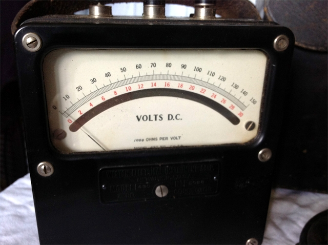
[img]cid:.0[/img]
Note the label at the bottom of the scale=plate that
says "1000 ohms per volt". This is another way of saying
that this instrument has a basic sensitivity of 1 milliampere
full scale and when making a reading on the 150 volt
scale, the instrument presents a "load" to the circuit
being measured of 1000 x 150 or 150,000 ohms. It will
"draw" 1 milliampere of current from the measurement node
at 150 volts.
These instruments were a grade trade off between
sensitivity, accuracy, linearity and calibration drift
due to temperature and age. But an instrument like
this is fitted with a 'mirrored scale'. The observer
lines up the pointer with the reflection of the pointer
so as to drive parallax error to zero. This instrument
could be both read and relied upon for readings with
certainty of 1% or better.
If you had measured the "output" from your open starter
contactor with such a device, no doubt the reading would
be zero . . . and commensurate with your expectations.
The day I got hired into Boeing (at $86/week) I
went down to Interstate Electronics and bought
a Triplett 630 multimeter. It was a 20,000 ohm/volt
instrument (50 microamp movement) and exemplary
technology for run-of-the-mill bench test
instruments. It replaced a 1000 ohm/volt meter
that somebody had given me some 5 years earlier.
I still have the 630. It was 20 times more sensitive
than the earlier instrument and offered accuracies
on the order of 2%.
But no doubt the Triplett would also say that
your contactor was working as expected.
Such devices were useless for many investigations into
the function of vacuum tubes. The source impedance of
many voltages of interest were so high that probing
the node with this voltmeter would also show zero
volts . . . and the circuit under test would cease
to function at all.
Probing through sensitive circuitry added new
requirements for sensitivity and isolation. This
was achieved with some form of amplification. A
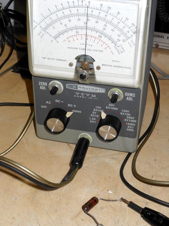
exemplar instrument is shown here:
[img]cid:.1[/img]
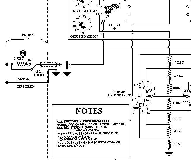
This Heathkit product has an input circuit that
looks like this:
[img]cid:.2[/img]
Notice the voltage divider of resistors that total up to
more than 9 megohms. Notice too a 1 meg resistor built
into the probe. The input impedance for this instrument
is over 10 megohms. Further, probing a node with a
combination of DC volts of interest that also carries
some signal (perhaps even high frequency RF) is only
very slightly affected by the probe. This instrument
is several hundred times more sensitive than the
device at the top of the page.
This kind of instrument may also have produced an
anomalous reading in the de-energized condition.
Modern digital voltmeters have input impedances on
the order of 20 megohms. Further, they do not provide
any isolation for probe-effects when measuring 'busy
circuits'. I have crafted a x10 probe for my Fluke
multimeter from an low capacity, oscilloscope probe
to conduct the kinds of measurements I used to do
with my Heathkit VTVM. Also, I have some load resistors
I can stack onto the voltmeter's test lead jacks that
deliberately degrade instrument sensitivity so that
readings are not influenced by small leakages.
The point of this soliloquy is to remind us
that not all observations provide good data
. . . but all data can be filtered through a
healthy level of skepticism supported by an
understanding of the circuit under test along
with the measuring device's limits.
Bob . . .
| | - The Matronics AeroElectric-List Email Forum - | | | Use the List Feature Navigator to browse the many List utilities available such as the Email Subscriptions page, Archive Search & Download, 7-Day Browse, Chat, FAQ, Photoshare, and much more:
http://www.matronics.com/Navigator?AeroElectric-List |
|
| Description: |
|
| Filesize: |
179.39 KB |
| Viewed: |
7726 Time(s) |

|
| Description: |
|
| Filesize: |
309.51 KB |
| Viewed: |
7726 Time(s) |
|
| Description: |
|
| Filesize: |
123.22 KB |
| Viewed: |
7726 Time(s) |
|
|
|
| Back to top |
|
|
rv8ch
Joined: 10 Jan 2006
Posts: 250
Location: Switzerland
|
| Posted: Sun Aug 05, 2012 10:56 am Post subject: Starter contactor leaking voltage |
|
|
Joe, Eric, Bob,
Thanks so much for the feedback - I tried the lamp, and of course it did not light up. Â Also used an older analog instrument, and it showed no indication of voltage. Â Thanks to your help and a bit of time reading up on impedance, I have a better understanding what is happening here. Â I'm really happy to have run across this "problem" as it allowed me to learn some new stuff. Â Thanks again!
Regards,
Mickey
On Sun, Aug 5, 2012 at 4:51 PM, Robert L. Nuckolls, III <nuckolls.bob(at)aeroelectric.com (nuckolls.bob(at)aeroelectric.com)> wrote:
| Quote: | New question (yes, I'm building very slowly) - I have the Van's starter contactor (Part Number = ES 24021) and when I apply 12v to the battery connection, I get about 0.4v on the starter connection. Ã This is before it is energized. Ã When I apply the 12v to the 'S' terminal, I get the full 12v on the starter terminal.
Is it normal for some voltage to "leak" even when the device is "idle"? Ã My battery contactors don't do this, and I don't have another starter contactor to test with.
Thanks,
Mickey
At 07:18 AM 8/5/2012, you wrote:
--> AeroElectric-List message posted by: "user9253" <fran4sew(at)banyanol.com (fran4sew(at)banyanol.com)>
Theoretically there should be NO leakage through the starter contactor. But the insulation used in the contactor is not perfect. There could be some insignificant leakage. Digital voltmeters have a very high input impedance which allows them to measure insignificant voltage. Try shorting the output terminal to ground with your fingers of one hand while measuring the voltage. Or use an old analog voltmeter which will give more meaningful measurements in this situation. Or use a very small 12v test lamp, the type used for automotive instrument illumination.
 I do not think there is enough leakage to worry about.
Joe
  My thoughts exactly. This thread illustrates
  a measurement conundrum that has existed since
  day one in the study and diagnosis of electron
  flow. The ideal measurement technique should be
  transparent to quantities being explored. The
  earliest precision voltmeters (ammeters with resistors
  in series) were excellent demonstrations of the
  best-we-knew-how-to-do at the time.
[img]cid:.0[/img]
   Note the label at the bottom of the scale=plate that
   says "1000 ohms per volt". This is another way of saying
   that this instrument has a basic sensitivity of 1 milliampere
   full scale and when making a reading on the 150 volt
   scale, the instrument presents a "load" to the circuit
   being measured of 1000 x 150 or 150,000 ohms. It will
   "draw" 1 milliampere of current from the measurement node
   at 150 volts.
   These instruments were a grade trade off between
   sensitivity, accuracy, linearity and calibration drift
   due to temperature and age. But an instrument like
   this is fitted with a 'mirrored scale'. The observer
   lines up the pointer with the reflection of the pointer
   so as to drive parallax error to zero. This instrument
   could be both read and relied upon for readings with
   certainty of 1% or better.
   If you had measured the "output" from your open starter
   contactor with such a device, no doubt the reading would
   be zero . . . and commensurate with your expectations.
   The day I got hired into Boeing (at $86/week) I
   went down to Interstate Electronics and bought
   a Triplett 630 multimeter. It was a 20,000 ohm/volt
   instrument (50 microamp movement) and exemplary
   technology for run-of-the-mill bench test
   instruments. It replaced a 1000 ohm/volt meter
   that somebody had given me some 5 years earlier.
   I still have the 630. It was 20 times more sensitive
   than the earlier instrument and offered accuracies
   on the order of 2%.
   But no doubt the Triplett would also say that
   your contactor was working as expected.
   Such devices were useless for many investigations into
   the function of vacuum tubes. The source impedance of
   many voltages of interest were so high that probing
   the node with this voltmeter would also show zero
   volts . . . and the circuit under test would cease
   to function at all.
   Probing through sensitive circuitry added new
   requirements for sensitivity and isolation. This
   was achieved with some form of amplification. A
   exemplar instrument is shown here:
[img]cid:.1[/img]
  This Heathkit product has an input circuit that
  looks like this:
[img]cid:.2[/img]
   Notice the voltage divider of resistors that total up to
   more than 9 megohms. Notice too a 1 meg resistor built
   into the probe. The input impedance for this instrument
   is over 10 megohms. Further, probing a node with a
   combination of DC volts of interest that also carries
   some signal (perhaps even high frequency RF) is only
   very slightly affected by the probe. This instrument
   is several hundred times more sensitive than the
   device at the top of the page.
   This kind of instrument may also have produced an
   anomalous reading in the de-energized condition.
   Modern digital voltmeters have input impedances on
   the order of 20 megohms. Further, they do not provide
   any isolation for probe-effects when measuring 'busy
   circuits'. I have crafted a x10 probe for my Fluke
   multimeter from an low capacity, oscilloscope probe
   to conduct the kinds of measurements I used to do
   with my Heathkit VTVM. Also, I have some load resistors
   I can stack onto the voltmeter's test lead jacks that
   deliberately degrade instrument sensitivity so that
   readings are not influenced by small leakages.
   The point of this soliloquy is to remind us
   that not all observations provide good data
   . . . but all data can be filtered through a
   healthy level of skepticism supported by an
   understanding of the circuit under test along
   with the measuring device's limits.
 Bob . . .
|
--
Mickey Coggins
| | - The Matronics AeroElectric-List Email Forum - | | | Use the List Feature Navigator to browse the many List utilities available such as the Email Subscriptions page, Archive Search & Download, 7-Day Browse, Chat, FAQ, Photoshare, and much more:
http://www.matronics.com/Navigator?AeroElectric-List |
|
| Description: |
|
| Filesize: |
309.51 KB |
| Viewed: |
7718 Time(s) |

|
| Description: |
|
| Filesize: |
123.22 KB |
| Viewed: |
7718 Time(s) |

|
| Description: |
|
| Filesize: |
179.39 KB |
| Viewed: |
7718 Time(s) |
|
_________________
Mickey Coggins
http://www.rv8.ch/ |
|
| Back to top |
|
|
henador_titzoff(at)yahoo.
Guest
|
| Posted: Sun Aug 05, 2012 12:00 pm Post subject: Starter contactor leaking voltage |
|
|
Eric,


 This has nothing to do with aviation other than avionics are built with ICs.  I would just like to know how not  including the power supply trace from pin to circuitry allows the chip circuitry to work as advertised (datasheet)?  I've never heard of a chip that worked  without intended power.  Since it was CMOS and CMOS is very  conservative with power, did it somehow derive its power from IO  signals?


 You must be an Analog Devices kind of guy.  I worked at Teradyne for several years. It was a lot of fun riding the train to South Station every weekday.


Henador Titzoff


--- On Sun, 8/5/12, Eric M. Jones <emjones(at)charter.net> wrote:

[quote]

From: Eric M. Jones <emjones(at)charter.net>

Subject: Re: Starter contactor leaking voltage

To: aeroelectric-list(at)matronics.com

Date: Sunday, August 5, 2012, 7:48 AM


--> AeroElectric-List message posted by: "Eric M. Jones" <[url=/mc/compose?to=emjones(at)charter.net]emjones(at)charter.net[/url]>


repost


      As others have mentioned, the problem is in how you use your tools...like the voltmeter.


       Imagine that you have a voltmeter that is infinitely sensitive (infinite impedance). Now it will measure the battery voltage even thru an open switch. In fact, it will measure 500 volts between your belt buckle and your shoe laces. And the top of your hat will be 1000 volts higher than the soles of your New Balance sneakers. You can actually extract some tiny amount of power this way.


      So meter impedance is not a lack of quality in a meter, it is a necessary and useful characteristic of the measuring device. And in a solid state circuit (like a diode), there will almost always be a voltage on the output that is similar to the input voltage even when the meter is off. And in fact the "leakage voltage" will not be able to light even the tiniest LED...so ignore it.


      I once designed a Cmos circuit where somebody (okay, me...) forgot to add the  power trace to the IC. Years later, an inquisitive technician, tracing an unrelated fault discovered it, but all the shipped product had worked just fine.


      So just don't make voltage measurements like this.


      See attached for a better way.


      --------


--------

Eric M. Jones

www.PerihelionDesign.com

113 Brentwood Drive

Southbridge, MA 01550

(508) 764-2072

emjones(at)charter.net


Read this topic online here:


http://forums.matronics.com/viewtopic.php?p=380088#380088


Attachments:


http://forums.matronics.com//files/diode_test_745.pdfhttp://www.matronics.com/Navigator=               - MATRONICS cs.com" bsp;               -Matt Dralle, List Adontribution" target="_blank">http://www.matronics.com/contribution [quote][b]
| | - The Matronics AeroElectric-List Email Forum - | | | Use the List Feature Navigator to browse the many List utilities available such as the Email Subscriptions page, Archive Search & Download, 7-Day Browse, Chat, FAQ, Photoshare, and much more:
http://www.matronics.com/Navigator?AeroElectric-List |
|
|
|
| Back to top |
|
|
nuckolls.bob(at)aeroelect
Guest
|
| Posted: Sun Aug 05, 2012 1:54 pm Post subject: Starter contactor leaking voltage |
|
|
At 01:54 PM 8/5/2012, you wrote:
| Quote: | Joe, Eric, Bob,
Thanks so much for the feedback - I tried the
lamp, and of course it did not light up. Â Also
used an older analog instrument, and it showed
no indication of voltage. Â Thanks to your help
and a bit of time reading up on impedance, I
have a better understanding what is happening
here. Â I'm really happy to have run across this
"problem" as it allowed me to learn some new stuff. Â Thanks again!
Regards,
Mickey
|
I've taken this posting to the List and fixed
some syntax/spelling issues, converted to a pdf
and posted it to AeroElectric.com article archives.
The cleaned up document is available at:
http://tinyurl.com/8oe5wbj
Bob . . .
| | - The Matronics AeroElectric-List Email Forum - | | | Use the List Feature Navigator to browse the many List utilities available such as the Email Subscriptions page, Archive Search & Download, 7-Day Browse, Chat, FAQ, Photoshare, and much more:
http://www.matronics.com/Navigator?AeroElectric-List |
|
|
|
| Back to top |
|
|
user9253
Joined: 28 Mar 2008
Posts: 1975
Location: Riley TWP Michigan
|
| Posted: Sun Aug 05, 2012 4:32 pm Post subject: Re: Starter contactor leaking voltage |
|
|
Many troubleshooters have come to the wrong conclusion when testing a circuit with a voltmeter without the circuit being loaded.  The troubleshooter might think, "The voltmeter reads 12 volts.  Therefore everything up to this point must be OK."  Without a load, that hypothesis could be incorrect.  No load means no current.  No current means no voltage drop.  So a voltmeter will read normal voltage even if there is unwanted high resistance in the circuit.  The high resistance could be due to a bad switch or a loose connection or corrosion or whatever.  Without current flowing through that resistance, there will be no voltage drop across it.  A voltmeter could read normal voltage when no current is flowing in a problem circuit.

Joe
| | - The Matronics AeroElectric-List Email Forum - | | | Use the List Feature Navigator to browse the many List utilities available such as the Email Subscriptions page, Archive Search & Download, 7-Day Browse, Chat, FAQ, Photoshare, and much more:
http://www.matronics.com/Navigator?AeroElectric-List |
|
_________________
Joe Gores |
|
| Back to top |
|
|
|
|
You cannot post new topics in this forum
You cannot reply to topics in this forum
You cannot edit your posts in this forum
You cannot delete your posts in this forum
You cannot vote in polls in this forum
You cannot attach files in this forum
You can download files in this forum
|
Powered by phpBB © 2001, 2005 phpBB Group
|

