 |
Matronics Email Lists
Web Forum Interface to the Matronics Email Lists
|
| View previous topic :: View next topic |
| Author |
Message |
bobnoffs
Joined: 04 Jul 2012
Posts: 137
Location: northern wi.
|
 Posted: Wed Aug 28, 2013 2:45 am Post subject: led trim display Posted: Wed Aug 28, 2013 2:45 am Post subject: led trim display |
 |
|
i have a ray allen trim display. it has a vertical row of led's. when i keey the mike [pilot or passenger ptt] the led that was lit brightly goes out and the top led lights up but dimly. is this wiring or interference from transmission? radio and indicator otherwise work perfect.


  bob noffs


  [quote][b]
| | - The Matronics AeroElectric-List Email Forum - | | | Use the List Feature Navigator to browse the many List utilities available such as the Email Subscriptions page, Archive Search & Download, 7-Day Browse, Chat, FAQ, Photoshare, and much more:
http://www.matronics.com/Navigator?AeroElectric-List |
|
|
|
| Back to top |
|
 |
Eric M. Jones
Joined: 10 Jan 2006
Posts: 565
Location: Massachusetts
|
| Posted: Wed Aug 28, 2013 7:29 am Post subject: Re: led trim display |
|
|
I like Ray Allen stuff, but the RP3 indicator and the trim boxes have limitations. One of them is that the full-scale voltage returned from the trim box pot is 1.2V. This is an issue when the wiring is close to the transmitter because the voltages are way down in the RFI/EMI mud. The other is the nature of the LED bar graph, which is an old design that can only get so bright, and updates to the design, like an LCD aren't happening.


See attached schematic.


My approach was to eliminate the indicator and turn the "trim box" into a true servo. I designed the TSCMR, true servo control to do that. Alternatively, I designed a more advanced version, BUT DON'T SELL IT, that uses 12V full-scale voltage at the trim box potentiometer, the bar graph, an "In Transit" led, a "locked" led and a setting knob.
| | - The Matronics AeroElectric-List Email Forum - | | | Use the List Feature Navigator to browse the many List utilities available such as the Email Subscriptions page, Archive Search & Download, 7-Day Browse, Chat, FAQ, Photoshare, and much more:
http://www.matronics.com/Navigator?AeroElectric-List |
|
| Description: |
|

Download |
| Filename: |
TSCMR_Installation Manual.pdf |
| Filesize: |
416.51 KB |
| Downloaded: |
522 Time(s) |
| Description: |
| RAC Trim Box and display schematic |
|
Download |
| Filename: |
RAC Trim and Trim Indicator Schematics.pdf |
| Filesize: |
110.35 KB |
| Downloaded: |
612 Time(s) |
_________________
Eric M. Jones
www.PerihelionDesign.com
113 Brentwood Drive
Southbridge, MA 01550
(508) 764-2072
emjones(at)charter.net |
|
| Back to top |
|
|
bobnoffs
Joined: 04 Jul 2012
Posts: 137
Location: northern wi.
|
| Posted: Wed Aug 28, 2013 11:27 pm Post subject: led trim display |
|
|
thanks for the replys. all in all i guess it is good news compared to improper wiring.


 bob noffs


On Wed, Aug 28, 2013 at 10:29 AM, Eric M. Jones <emjones(at)charter.net (emjones(at)charter.net)> wrote:

 [quote]--> AeroElectric-List message posted by: "Eric M. Jones" <emjones(at)charter.net (emjones(at)charter.net)>


 I like Ray Allen stuff, but the RP3 indicator and the trim boxes have limitations. One of them is that the full-scale voltage returned from the trim box pot is 1.2V. This is an issue when the wiring is close to the transmitter because the voltages are way down in the RFI/EMI mud. The other is the nature of the LED bar graph, which is an old design that can only get so bright, and updates to the design, like an LCD aren't happening.


 See attached schematic.


 My approach was to eliminate the indicator and turn the "trim box" into a true servo. I designed the TSCMR, true servo control to do that. Alternatively, I designed a more advanced version, BUT DON'T SELL IT, that uses 12V full-scale voltage at the trim box potentiometer, the bar graph, an "In Transit" led, a "locked" led and a setting knob.


 --------

 Eric M. Jones

 www.PerihelionDesign.com

 113 Brentwood Drive

 Southbridge, MA 01550

 [url=tel:%28508%29%20764-2072](508) 764-2072[/url]

 emjones(at)charter.net


 Read this topic online here:


 http://forums.matronics.com/viewtopic.php?p=407633#407633


 Attachments:


 http://forums.matronics.com//files/tscmr_installation_manual_416.pdf

 http://forums.matronics.com//files/rac_trim_and_trim_indicator_schematics_433.pdf


 ===========

 -List" target="_blank">http://www.matronics.com/Navigator?AeroElectric-List

 ===========

 http://forums.matronics.com

 ===========

 le, List Admin.

 ="_blank">http://www.matronics.com/contribution

 ===========


 [b]
| | - The Matronics AeroElectric-List Email Forum - | | | Use the List Feature Navigator to browse the many List utilities available such as the Email Subscriptions page, Archive Search & Download, 7-Day Browse, Chat, FAQ, Photoshare, and much more:
http://www.matronics.com/Navigator?AeroElectric-List |
|
|
|
| Back to top |
|
|
rparigoris
Joined: 24 Nov 2009
Posts: 812
|
| Posted: Thu Aug 29, 2013 4:20 am Post subject: led trim display |
|
|
Hi Bob

 	The Europa that I am building uses a Ray Allen for pitch trimming. I have read over the years that some folks have the same problem you are experiencing when transmitting. It seems that the greatest success is keeping the wire run as far from antenna and associated wires as you can. I installed 5 conductor twisted with shielding from ACS:

 	http://www.europaowners.org/main.php?g2_itemId=30484

 	Ron Parigoris    [quote][b]
| | - The Matronics AeroElectric-List Email Forum - | | | Use the List Feature Navigator to browse the many List utilities available such as the Email Subscriptions page, Archive Search & Download, 7-Day Browse, Chat, FAQ, Photoshare, and much more:
http://www.matronics.com/Navigator?AeroElectric-List |
|
|
|
| Back to top |
|
|
bobnoffs
Joined: 04 Jul 2012
Posts: 137
Location: northern wi.
|
| Posted: Thu Aug 29, 2013 12:08 pm Post subject: led trim display |
|
|
it is a very minor thing. if fact i saw it 6 months ago and it wasn't until last week i keyed the mike and say the led display dance that i remembered it happened before. guess i don't look at my trim while talking! there! i am used to it already. now, it it changed the trim that would be something else.
bob noffs
On Thu, Aug 29, 2013 at 7:18 AM, <rparigor(at)suffolk.lib.ny.us (rparigor(at)suffolk.lib.ny.us)> wrote:
[quote]
Hi Bob
The Europa that I am building uses a Ray Allen for pitch trimming. I have read over the years that some folks have the same problem you are experiencing when transmitting. It seems that the greatest success is keeping the wire run as far from antenna and associated wires as you can. I installed 5 conductor twisted with shielding from ACS:
http://www.europaowners.org/main.php?g2_itemId=30484
Ron Parigoris | Quote: |
ist" target="_blank">http://www.matronics.com/Navigator?AeroElectric-List
ttp://forums.matronics.com
_blank">http://www.matronics.com/contribution
|
[b]
| | - The Matronics AeroElectric-List Email Forum - | | | Use the List Feature Navigator to browse the many List utilities available such as the Email Subscriptions page, Archive Search & Download, 7-Day Browse, Chat, FAQ, Photoshare, and much more:
http://www.matronics.com/Navigator?AeroElectric-List |
|
|
|
| Back to top |
|
|
nuckolls.bob(at)aeroelect
Guest
|
| Posted: Fri Aug 30, 2013 8:34 am Post subject: led trim display |
|
|
At 07:18 AM 8/29/2013, you wrote:
| Quote: | Hi Bob
The Europa that I am building uses a Ray Allen for pitch trimming. I have read over the years that some folks have the same problem you are experiencing when transmitting. It seems that the greatest success is keeping the wire run as far from antenna and associated wires as you can. I installed 5 conductor twisted with shielding from ACS:
http://www.europaowners.org/main.php?g2_itemId=30484
Ron Parigoris |
After pondering schematics for the trim indicator,
the reason for it's sensitivity to RF becomes
apparent. The design was never evaluated and
crafted for immunity to RF interference. There
are critical components missing from the design.
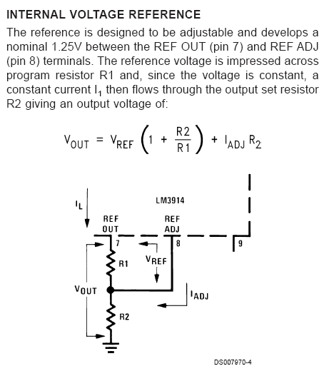
I note further that voltage used to excite the
potentiometer in the actuator is the rudimentary
1.2 volts supplied by the internal reference
regulator. An excerpt from the LM3914 specifications
states . . .
[img]cid:.0[/img]
A higher reference voltage increases noise immunity
for the A/D conversion and less jitter or uncertainty
in the bar-to-bar transitions for the display. I would
have considered at least a 5v reference and probably
some higher value still by adding R1/R2 as described
above.
Referring to the data sheet again we see that bias (or
input load) current at the signal pin (5) is 100nA or
less.
[img]cid:.1[/img]
This means that we could put a resistor in series with
pin (5) of say 10,000 ohms and exert less than 1 millivolt
of error in the signal voltage. At the same time we would
add say 1000pF capacitor from pin 5 to ground (pin 2).
This mod alone might fix the RF sensitivity problem. As
a matter of good design practice I would bypass the power
input pin (3) to ground as well.
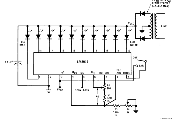
The designers also missed a great opportunity to make
their product truly 'universal' by not exploiting the
expanded scale voltmeter example in the specifications.
[img]cid:.2[/img]
Adding a few components and a couple of pots would
allow the indicator to be tailored to a specific installation
such that full down trim would illuminate the bottom led,
full up trim the top led . . . irrespective of the actuator's
as-installed stroke.
I offered to help these guys with this product line at
OSH about 20 years ago but they weren't interested. They
also appear to have learned nothing new by way of feedback
from the field as to how their product has been performing.
Getting back to the original query for driving two indicators
from one actuator pot, a study of the schematics and data
suggests that two indicators running in parallel on one pot
will not significantly 'load' the signal. Hence, you can wire
one indicator to the actuator per installation instructions.
Then wire the second indicator wire for wire in parallel
with the first but leave its potentiometer excitation voltage
wire (orange) floating.
Bottom line is that this indicator would benefit greatly
from due diligence to rudimentary operating characteristics
and limitations. Adding the resistor and capacitor described
above may fix the RF sensitivity issue. The idea that an
installer should be burdened with careful positioning of
wires to mitigate design flaws is decidedly un-cool.
Bob . . .
| | - The Matronics AeroElectric-List Email Forum - | | | Use the List Feature Navigator to browse the many List utilities available such as the Email Subscriptions page, Archive Search & Download, 7-Day Browse, Chat, FAQ, Photoshare, and much more:
http://www.matronics.com/Navigator?AeroElectric-List |
|
| Description: |
|
| Filesize: |
97.74 KB |
| Viewed: |
7978 Time(s) |
|
| Description: |
|
| Filesize: |
10.74 KB |
| Viewed: |
7978 Time(s) |

|
| Description: |
|
| Filesize: |
65.94 KB |
| Viewed: |
7978 Time(s) |
|
|
|
| Back to top |
|
|
spcialeffects
Joined: 29 Aug 2012
Posts: 306
Location: Kent
|
| Posted: Tue Dec 13, 2016 11:57 am Post subject: Re: led trim display |
|
|
| nuckolls.bob(at)aeroelect wrote: | At 07:18 AM 8/29/2013, you wrote:
| Quote: | Hi Bob
The Europa that I am building uses a Ray Allen for pitch trimming. I have read over the years that some folks have the same problem you are experiencing when transmitting. It seems that the greatest success is keeping the wire run as far from antenna and associated wires as you can. I installed 5 conductor twisted with shielding from ACS:
http://www.europaowners.org/main.php?g2_itemId=30484
Ron Parigoris |
After pondering schematics for the trim indicator,
the reason for it's sensitivity to RF becomes
apparent. The design was never evaluated and
crafted for immunity to RF interference. There
are critical components missing from the design.
I note further that voltage used to excite the
potentiometer in the actuator is the rudimentary
1.2 volts supplied by the internal reference
regulator. An excerpt from the LM3914 specifications
states . . .
[img]cid:.0[/img]
A higher reference voltage increases noise immunity
for the A/D conversion and less jitter or uncertainty
in the bar-to-bar transitions for the display. I would
have considered at least a 5v reference and probably
some higher value still by adding R1/R2 as described
above.
Referring to the data sheet again we see that bias (or
input load) current at the signal pin (5) is 100nA or
less.
[img]cid:.1[/img]
This means that we could put a resistor in series with
pin (5) of say 10,000 ohms and exert less than 1 millivolt
of error in the signal voltage. At the same time we would
add say 1000pF capacitor from pin 5 to ground (pin 2).
This mod alone might fix the RF sensitivity problem. As
a matter of good design practice I would bypass the power
input pin (3) to ground as well.
The designers also missed a great opportunity to make
their product truly 'universal' by not exploiting the
expanded scale voltmeter example in the specifications.
[img]cid:.2[/img]
Adding a few components and a couple of pots would
allow the indicator to be tailored to a specific installation
such that full down trim would illuminate the bottom led,
full up trim the top led . . . irrespective of the actuator's
as-installed stroke.
I offered to help these guys with this product line at
OSH about 20 years ago but they weren't interested. They
also appear to have learned nothing new by way of feedback
from the field as to how their product has been performing.
Getting back to the original query for driving two indicators
from one actuator pot, a study of the schematics and data
suggests that two indicators running in parallel on one pot
will not significantly 'load' the signal. Hence, you can wire
one indicator to the actuator per installation instructions.
Then wire the second indicator wire for wire in parallel
with the first but leave its potentiometer excitation voltage
wire (orange) floating.
Bottom line is that this indicator would benefit greatly
from due diligence to rudimentary operating characteristics
and limitations. Adding the resistor and capacitor described
above may fix the RF sensitivity issue. The idea that an
installer should be burdened with careful positioning of
wires to mitigate design flaws is decidedly un-cool.
Bob . . . |
Hi bob. I have this problem. When I press the PTT the ray Allen led flickers and dims. I've read your post above but don't really understand what is need to rectify the problem. In the simplest of language how would I go about to resolve the problem?
Many thanks Frank
| | - The Matronics AeroElectric-List Email Forum - | | | Use the List Feature Navigator to browse the many List utilities available such as the Email Subscriptions page, Archive Search & Download, 7-Day Browse, Chat, FAQ, Photoshare, and much more:
http://www.matronics.com/Navigator?AeroElectric-List |
|
|
|
| Back to top |
|
|
|
|
You cannot post new topics in this forum
You cannot reply to topics in this forum
You cannot edit your posts in this forum
You cannot delete your posts in this forum
You cannot vote in polls in this forum
You cannot attach files in this forum
You can download files in this forum
|
Powered by phpBB © 2001, 2005 phpBB Group
|

