 |
Matronics Email Lists
Web Forum Interface to the Matronics Email Lists
|
| View previous topic :: View next topic |
| Author |
Message |
Fred Klein
Joined: 26 Mar 2012
Posts: 503
|
 Posted: Fri Oct 11, 2013 10:36 pm Post subject: EXP 2 Bus workaround Posted: Fri Oct 11, 2013 10:36 pm Post subject: EXP 2 Bus workaround |
 |
|
Guys...electrical wizards...
With full knowledge of my ignorance of all things electric but with only scant knowledge of the challenges which lay ahead, some time ago I purchased an EXP 2 Bus, thinking that having one would simplify many issues and offset some of the novelty inherent with my auto engine conversion, a MPEFIed derivative of a EA81 Subaru built by RAM Performance Aero Engines which is liquid cooled. Aircraft is a Europa XS monowheel which is typically powered w/ a 912S or 914.
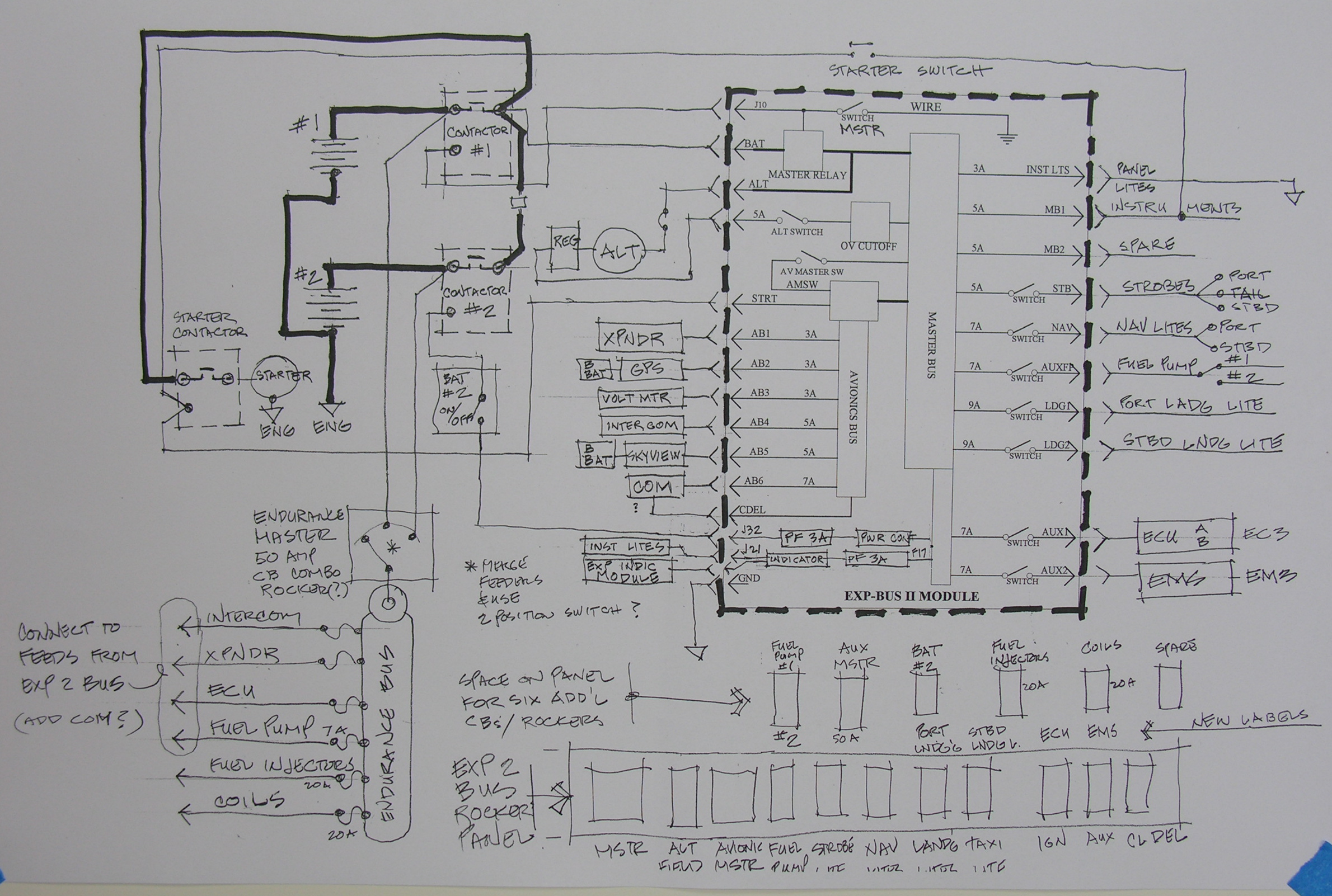
I've been struggling to layout a circuit diagram which combines the EXP 2 BUS configured for an external solenoid with the dual battery / single alternator diagram Z-19 in the "Connection".
I have made a number of decisions which have committed me to the digital world including:
- an engine w/ electronic ignition, fuel injection, and an ECU (EC3, Real World Systems) which came w/ the engine,
- a digital EMS (EM3, Real World Systems) which "talks" w/ the ECU,
- a digital EFIS (Skyview) including moving map, digital terrain, Transponder, COM, and Intercom.
By selecting an auto engine conversion, I have committed to:
- one alternator, belt driven,
- one coolant pump, belt driven,
- single spark plug in each cylinder.
Additionally, in order to provide redundancy, the engine and control system includes:
- dual batteries, presently planned to be Odyssey 680's,
- two independent high pressure fuel pumps, each w/ their own filter,
- independent back up battery for Skyview,
- independent back up battery for stand-alone GPS, Garmin 396,
- redundant motherboards (A and B) for the ECU which are toggled from the panel.
OK...about the EXP BUS...I've now read many reports (including the VAF threads) which point out its shortcomings...but having spent $550 for it and its companion Indicator Module, and given my inexperience and lack of knowledge of things electrical, I still believe it has a place in my panel, so I hope any critique of what I'm up to doesn't focus on simply getting rid of it.
The main problem I'm having with the EXP BUS is that it simply does not have the two 20 amp circuits my engine guy sez are essential...one for the fuel injectors, and one for the coils. On my circuit diagram, I attempt to address it by running those two circuits off an Endurance bus which avoids the EXP BUS entirely.
I do use available circuits in the EXP BUS for the ECU, the EMS, and the fuel pumps; these components are also fed from the Endurance bus.
I have space on my panel (just above the EXP BUS, and below the Skyview flat screen) for a row of 6 - CB / switches which are presently planned to be:
- rocker or toggle between Fuel Pump #1 and Fuel Pump #2,
- Endurance Master Switch / 50 amp CB,
- Battery #2 ON / OFF,
- 20 amp CB for Fuel Injectors,
- 20 amp CB for Coils,
- spare
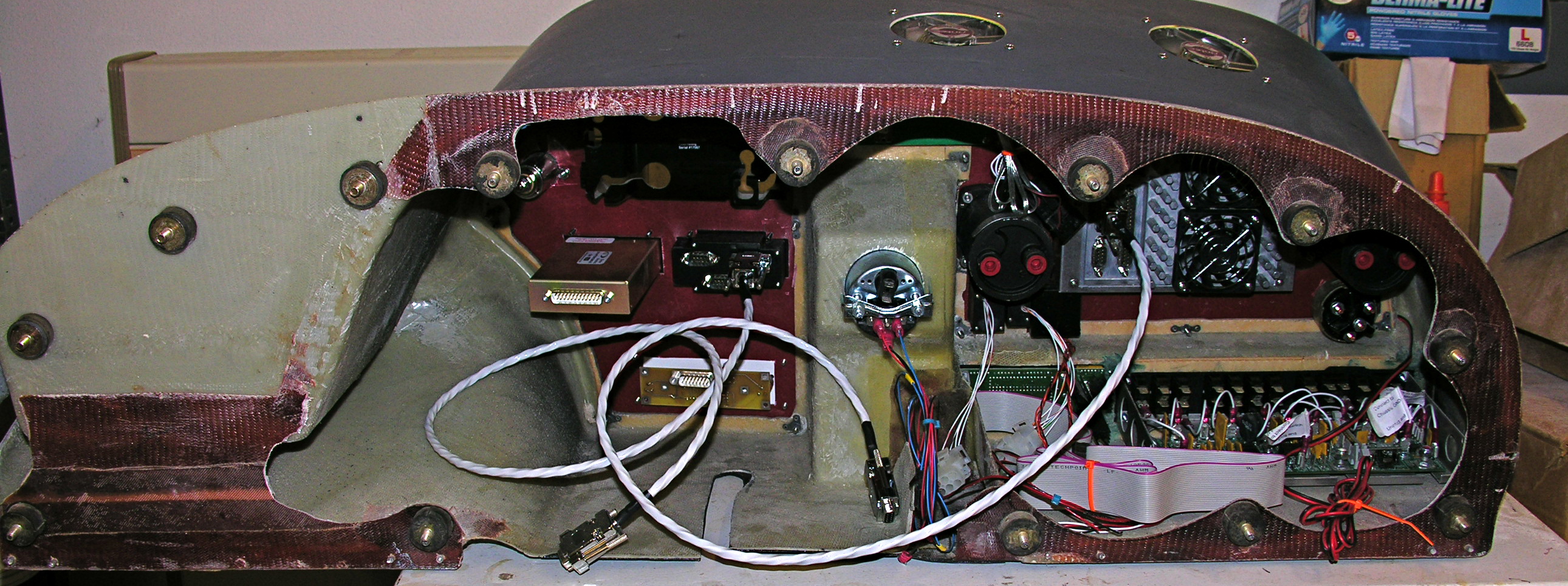
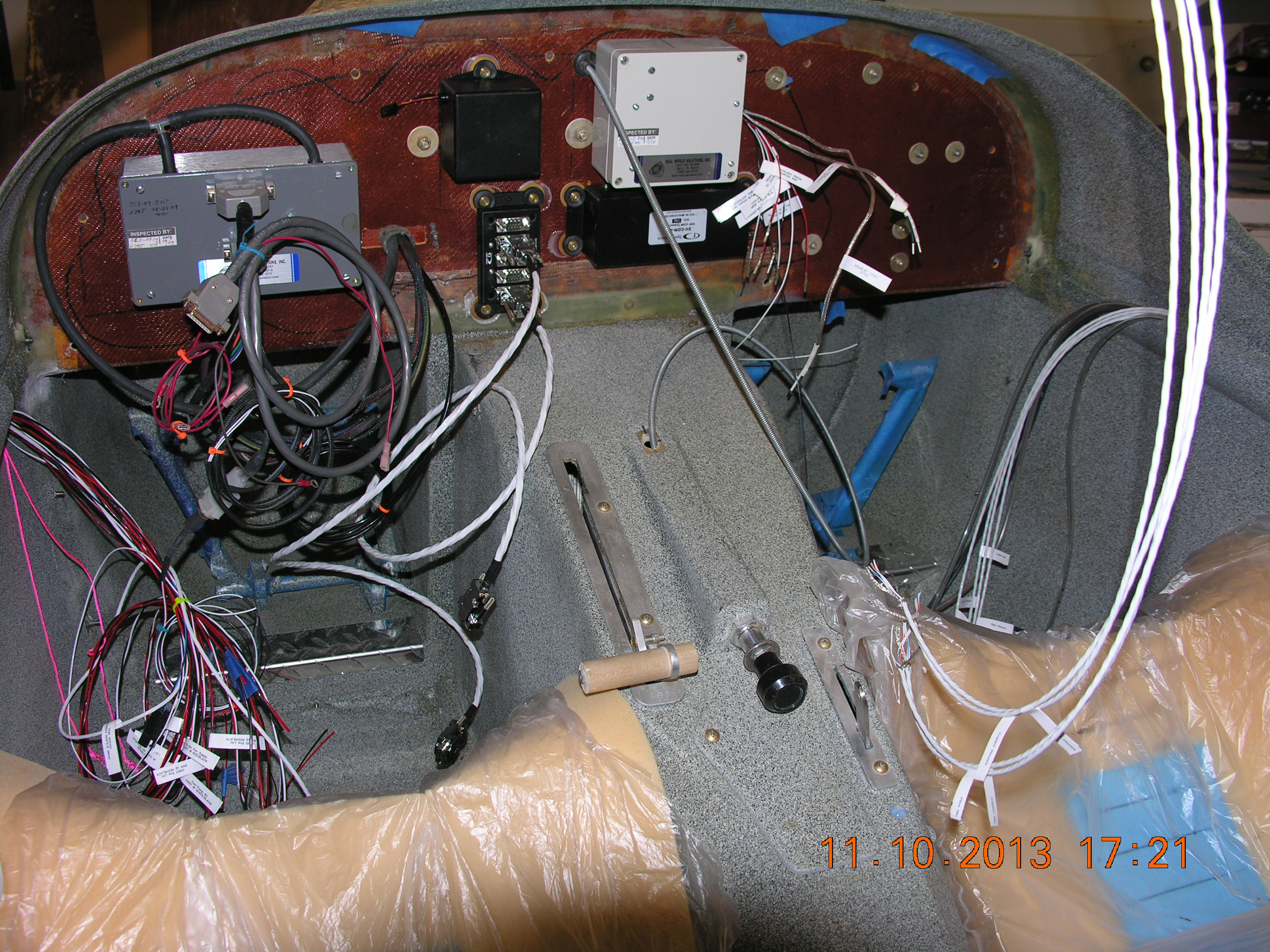
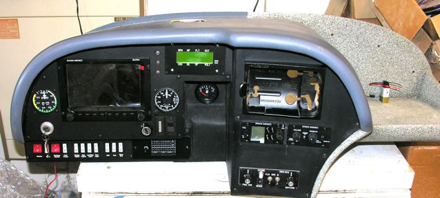
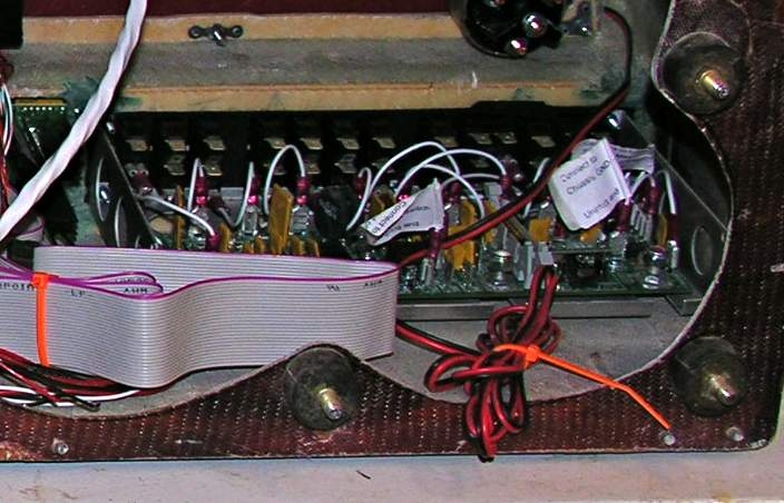
Attached are pixs of my instrument panel in its present state, and a proposed circuit diagram.
I'd be most appreciative of any comments, and particularly those which point our errors or weakness in the diagram.
Fred
| | - The Matronics AeroElectric-List Email Forum - | | | Use the List Feature Navigator to browse the many List utilities available such as the Email Subscriptions page, Archive Search & Download, 7-Day Browse, Chat, FAQ, Photoshare, and much more:
http://www.matronics.com/Navigator?AeroElectric-List |
|
| Description: |
|
| Filesize: |
922.48 KB |
| Viewed: |
17751 Time(s) |

|
| Description: |
|
| Filesize: |
1.22 MB |
| Viewed: |
17750 Time(s) |
|
| Description: |
|
| Filesize: |
1.62 MB |
| Viewed: |
17750 Time(s) |
|
| Description: |
|
| Filesize: |
1.16 MB |
| Viewed: |
17750 Time(s) |
|
|
|
| Back to top |
|
 |
user9253
Joined: 28 Mar 2008
Posts: 1972
Location: Riley TWP Michigan
|
| Posted: Sat Oct 12, 2013 7:07 am Post subject: Re: EXP 2 Bus workaround |
|
|
Having an avionics master switch is a bad idea.  It is a single point of failure.

The endurance master switch is another single point of failure.  It is more likely to fail than a battery.  50 amps seems too big.

  The cost of the EXP BUS should not influence the decision to use or not use it.  "inexperience and lack of knowledge of things electrical" is a good reason NOT to use the  EXP BUS.  Discrete components are easier to troubleshoot and replace.

  You are better off using one of Bob Nuckolls well proven designs, perhaps Z-19/RB (with E-Bus Relay) modified to meet the unique engine requirements.

Joe
| | - The Matronics AeroElectric-List Email Forum - | | | Use the List Feature Navigator to browse the many List utilities available such as the Email Subscriptions page, Archive Search & Download, 7-Day Browse, Chat, FAQ, Photoshare, and much more:
http://www.matronics.com/Navigator?AeroElectric-List |
|
_________________
Joe Gores |
|
| Back to top |
|
|
nuckolls.bob(at)aeroelect
Guest
|
| Posted: Sat Oct 12, 2013 7:43 am Post subject: EXP 2 Bus workaround |
|
|
I've been struggling to layout a circuit diagram which combines the EXP 2 BUS configured for an external solenoid with the dual battery / single alternator diagram Z-19 in the "Connection".


     I understand the conditions that are a basis

     for your struggles. You've purchased a lot of 'stuff',

     cut holes in then panel and mounted it . . . and

     you're only now beginning to sift the bits and

     pieces in a quest for the elegant solution.


     It's not clear to me how the List can be a great deal

     of help . . . many options available to you at the

     clean-sheet-of-paper stage for your planning are no

     longer applicable.


     The EXP-Bus architecture which was already pretty

     busy is going to get still more complicated . . .

     not a very pilot or maintenance friendly situation.


 I have made a number of decisions which have committed me to the digital world including:


 - an engine w/ electronic ignition, fuel injection, and an ECU (EC3, Real World Systems) which came w/ the engine,


 Additionally, in order to provide redundancy, the engine and control system includes:


 - dual batteries, presently planned to be Odyssey 680's,


        What are the energy demands to run the engine? If

        you were powering nothing but the engine, how many

        amps are required to keep the fires lit? What are

        your design goals for battery only endurance? Will

        one battery meet those goals or will you be taxing

        both?


 - independent back up battery for Skyview,


 - independent back up battery for stand-alone GPS, Garmin 396,


        With two fat batteries on board, backing up these items

        with still more batteries seems excessively 'redundant'.

        If the ship's batteries are depleted, the value

        of having the panel lit seems contrary to the

        purpose of having an 'endurance mode' of flight.


        The idea is to have a carefully crafted Plan-B

        that gets wheels on the ground before you (a)

        run out of fuel and/or (b) run out of electrons.

        Critical LOADS multiplied by TIME are the driving

        factor. Do you know what those numbers are?


 - redundant motherboards (A and B) for the ECU which are toggled from the panel.


        This architecture is not clear from your drawings.

        How do TWO motherboards get switched into and out

        of service?


 OK...about the EXP BUS...I've now read many reports (including the VAF threads) which point out  its shortcomings...but having spent $550 for it and its companion Indicator Module, and given my inexperience and lack of knowledge of things electrical, I still believe it has a place in my panel, so I hope any critique of what I'm up to doesn't focus on simply getting rid of it.


         Won't do that  . . . but at the same time, be aware

         that contributions from the List will be adjustments

         to make do with what already exists as opposed

         the artfully tailored design. The end result

         would not be a candidate for a new z-figure . . .

         in other words, not recommended for new design.


 The main problem I'm having with the EXP BUS is that it simply does not have the two 20 amp circuits my engine guy sez are essential...one for the fuel injectors, and one for the coils. On my circuit diagram, I attempt to address it by running those two circuits off an Endurance bus which avoids the EXP BUS entirely.


         That seems reasonable. Z-19 suggests two

         battery busses with options to run the engine

         from either bus.


 I do use available circuits in the EXP BUS for the ECU, the EMS, and the fuel pumps; these components

 are also fed from the Endurance bus.


         I suggest you divorce the engine from the EXP-Bus

         entirely and plan on running the engine from its

         own battery with an option for running it from the

         main battery. You show three feeders to coils, injectors

         and ECU. What is the recommended protection level for

         each of these feeders?


 I have space on my panel (just above the EXP BUS, and below the Skyview flat screen)

 for a row of 6 - CB / switches which are presently planned to be:


 - rocker or toggle between Fuel Pump #1 and Fuel Pump #2,

 - Endurance Master Switch / 50 amp CB,

 - Battery #2 ON / OFF,

 - 20 amp CB for Fuel Injectors,

 - 20 amp CB for Coils,

 - spare


        That's a LOT of controls with risks for not

        getting the right combination of switches open/closed

        when things are not going well under the cowl . . .


 Attached are pixs of my instrument panel in its present state, and a proposed circuit diagram.

 I'd be most appreciative of any comments, and particularly those which point our errors or weakness in the diagram.


         We'll do what we can but your meatloaf is already

         in then pan and we're only now joining the conversation

         about ways to make it taste better.


   Bob . . .    [quote][b]
| | - The Matronics AeroElectric-List Email Forum - | | | Use the List Feature Navigator to browse the many List utilities available such as the Email Subscriptions page, Archive Search & Download, 7-Day Browse, Chat, FAQ, Photoshare, and much more:
http://www.matronics.com/Navigator?AeroElectric-List |
|
|
|
| Back to top |
|
|
Fred Klein
Joined: 26 Mar 2012
Posts: 503
|
| Posted: Sat Oct 12, 2013 8:03 am Post subject: EXP 2 Bus workaround |
|
|
On Oct 12, 2013, at 8:07 AM, user9253 wrote:
| Quote: |
Having an avionics master switch is a bad idea. It is a single point of failure.
The endurance master switch is another single point of failure. It is more likely to fail than a battery. 50 amps seems too big.
The cost of the EXP BUS should not influence the decision to use or not use it. "inexperience and lack of knowledge of things electrical" is a good reason NOT to use the EXP BUS. Discrete components are easier to troubleshoot and replace.
You are better off using one of Bob Nuckolls well proven designs, perhaps Z-19/RB (with E-Bus Relay) modified to meet the unique engine requirements.
|
Joe...I thank you for your succinct and prompt assessment...much to ponder...as I wrote, I've struggled in my efforts to integrate the EXP Bus w/ Z-19 and to overcome the limitations of the EXP Bus w/ respect to my "unique engine requirements".
As you point out, the 50 amp size of the endurance master switch is too big...after reviewing my notes, I see that the injectors draw 1 to 2 amps each as do the coils...I'd misread a note calling for separate 20 amp circuits for both injectors and coils.
As for the EXP Bus, I could bring myself to discard it completely if I can conclude that by doing so, it would solve more problems than it would create. My decision to buy it was based upon seeing it in a friend's CAM 125 powered Europa; a retired RCAF senior test pilot, he admitted electronic ignorance and believed it saved him a lot of time and trouble.
Thanks again,
Fred
| | - The Matronics AeroElectric-List Email Forum - | | | Use the List Feature Navigator to browse the many List utilities available such as the Email Subscriptions page, Archive Search & Download, 7-Day Browse, Chat, FAQ, Photoshare, and much more:
http://www.matronics.com/Navigator?AeroElectric-List |
|
|
|
| Back to top |
|
|
nuckolls.bob(at)aeroelect
Guest
|
| Posted: Sat Oct 12, 2013 8:38 am Post subject: EXP 2 Bus workaround |
|
|
At 10:07 AM 10/12/2013, you wrote:
| Quote: |
Having an avionics master switch is a bad idea. It is a single
point of failure.
|
Let's ponder the possibility of making the AV master
switch the e-bus alternate feed. This would require that
the upstream side of the switch be fed from the ship's
battery bus . . . and a diode feed be added from main
bus to the avionics cum e-bus.
| Quote: | The endurance master switch is another single point of failure. It
is more likely to fail than a battery. 50 amps seems too big.
|
Yeah . . . if we can get all the numbers for running
the engine, perhaps we can move toward a Z-19 configuration
that eliminates the need for a single switch to manage
all engine power feeders.
| Quote: | The cost of the EXP BUS should not influence the decision to use
or not use it. "inexperience and lack of knowledge of things
electrical" is a good reason NOT to use the EXP BUS. Discrete
components are easier to troubleshoot and replace.
You are better off using one of Bob Nuckolls well proven designs,
perhaps Z-19/RB (with E-Bus Relay) modified to meet the unique
engine requirements.
|
It may be possible/practical to get there without taking
a chain-saw to the panel. I don't know what the switches
are like on the EXP-Bus but they can't be any worse than
those used on the C-150 for a decade or so . . . and while
a significant maintenance item for the TC world with
$50 shop labor rates, many of those switches did just
fine for a long time.
How can we eliminate single points of failure and leave
the EXP-Bus largely intact?
Another point I've pondered is the idea of taking the
alternator b-lead to the battery or starter contactors
through a current limiter and not bringing the feeder
into the cockpit.
Bob . . .
| | - The Matronics AeroElectric-List Email Forum - | | | Use the List Feature Navigator to browse the many List utilities available such as the Email Subscriptions page, Archive Search & Download, 7-Day Browse, Chat, FAQ, Photoshare, and much more:
http://www.matronics.com/Navigator?AeroElectric-List |
|
|
|
| Back to top |
|
|
bbradburry(at)bellsouth.n
Guest
|
| Posted: Sat Oct 12, 2013 8:43 am Post subject: EXP 2 Bus workaround |
|
|
Fred,

Z-19 has a battery buss for each of the batteries.  If you have an

electrically dependent engine, you should run everything that the engine

needs to keep operating off of those battery busses.  I am talking about the

engine controller, fuel pumps, injector power, igniter power, etc..


You should be able to shut off the master and never have a hiccup from your

engine.  I would not put anything you need to remain in the air thru that

EXP BUS.


Bill B


--
| | - The Matronics AeroElectric-List Email Forum - | | | Use the List Feature Navigator to browse the many List utilities available such as the Email Subscriptions page, Archive Search & Download, 7-Day Browse, Chat, FAQ, Photoshare, and much more:
http://www.matronics.com/Navigator?AeroElectric-List |
|
|
|
| Back to top |
|
|
nuckolls.bob(at)aeroelect
Guest
|
| Posted: Sat Oct 12, 2013 8:48 am Post subject: EXP 2 Bus workaround |
|
|
| Quote: |
As you point out, the 50 amp size of the endurance master switch is
too big...after reviewing my notes, I see that the injectors draw 1
to 2 amps each as do the coils...I'd misread a note calling for
separate 20 amp circuits for both injectors and coils.
|
Aha! that's good to hear . . . What's the
ECU draw?
| Quote: | As for the EXP Bus, I could bring myself to discard it completely if
I can conclude that by doing so, it would solve more problems than
it would create. My decision to buy it was based upon seeing it in a
friend's CAM 125 powered Europa; a retired RCAF senior test pilot,
he admitted electronic ignorance and believed it saved him a lot of
time and trouble.
|
These things DO save a lot of time if you can
use them plug-n-play with the architecture around
which the panel was designed. The EXP-Bus is
tailored to the legacy TC aircraft systems with
avionics bus, no battery buss(es), b-lead coming
into the cockpit, etc.
There are tens of thousands of airplanes carrying
happy pilots around with that architecture so there's
noting 'wrong' with it. But incorporating alternative
design goals into a cookie-cutter product can be
a challenge . . . let's see what we can do with it.
Fred, is your alternator internally regulated? Are
you amenable to modifying it for compatibility with
external management of over-voltage events?
Bob . . .
| | - The Matronics AeroElectric-List Email Forum - | | | Use the List Feature Navigator to browse the many List utilities available such as the Email Subscriptions page, Archive Search & Download, 7-Day Browse, Chat, FAQ, Photoshare, and much more:
http://www.matronics.com/Navigator?AeroElectric-List |
|
|
|
| Back to top |
|
|
Fred Klein
Joined: 26 Mar 2012
Posts: 503
|
| Posted: Sat Oct 12, 2013 8:57 am Post subject: EXP 2 Bus workaround |
|
|
On Oct 12, 2013, at 8:43 AM, Robert L. Nuckolls, III wrote:
| Quote: | I've been struggling to layout a circuit diagram which combines the EXP 2 BUS configured for an external solenoid with the dual battery / single alternator diagram Z-19 in the "Connection".
I understand the conditions that are a basis for your struggles. |
Bob,
Thank you for your thoughtful, point by point dissection of my posting...you raise a number of questions which I know I need to have answered...and I appreciate your restraint and good humor.
It may take a while to sort out things...you're quite correct in writing that I am on "a quest for the elegant solution" for what goes on behind the panel as well in as all other aspects of my aircraft.
Certainly my intention when purchasing an EMS designed to compliment my ECU, an integrated avionics suite like Skyview, and the EXP Bus for that matter, was to eliminate as many "seams" as possible.
With utmost respect,
Fred
[quote][b]
| | - The Matronics AeroElectric-List Email Forum - | | | Use the List Feature Navigator to browse the many List utilities available such as the Email Subscriptions page, Archive Search & Download, 7-Day Browse, Chat, FAQ, Photoshare, and much more:
http://www.matronics.com/Navigator?AeroElectric-List |
|
|
|
| Back to top |
|
|
Fred Klein
Joined: 26 Mar 2012
Posts: 503
|
| Posted: Sat Oct 12, 2013 9:21 am Post subject: EXP 2 Bus workaround |
|
|
On Oct 12, 2013, at 9:48 AM, Robert L. Nuckolls, III wrote:
| Quote: | | Quote: | As you point out, the 50 amp size of the endurance master switch is too big...after reviewing my notes, I see that the injectors draw 1 to 2 amps each as do the coils...I'd misread a note calling for separate 20 amp circuits for both injectors and coils.
|
Aha! that's good to hear . . . What's the ECU draw?
|
Bob...ECU draws 1/2 amp...(exclusive of fuel injectors and coils)
| Quote: |
| Quote: | As for the EXP Bus, I could bring myself to discard it completely if I can conclude that by doing so, it would solve more problems than it would create. My decision to buy it was based upon seeing it in a friend's CAM 125 powered Europa; a retired RCAF senior test pilot, he admitted electronic ignorance and believed it saved him a lot of time and trouble.
|
These things DO save a lot of time if you can
use them plug-n-play with the architecture around
which the panel was designed.
|
...which indeed was my intention...and, I might add, that pulling the EXP from my instrument panel module and replacing it w/ a blank plate is a 15 min. job...no hack saw req'd...
| Quote: | The EXP-Bus is tailored to the legacy TC aircraft systems with
avionics bus, no battery buss(es), b-lead coming
into the cockpit, etc.
There are tens of thousands of airplanes carrying
happy pilots around with that architecture so there's
noting 'wrong' with it. But incorporating alternative
design goals into a cookie-cutter product can be
a challenge . . . let's see what we can do with it.
|
...I'm reluctant to throw the baby out w/ the bathwater...
| Quote: |
Fred, is your alternator internally regulated?
|
...yes...
| Quote: | Are you amenable to modifying it for compatibility with
external management of over-voltage events?
|
...the very thought of doing so fills me w/ dread, and first I'd like to research and determine to what extent it manages over-voltage events internally...
Fred
[quote][b]
| | - The Matronics AeroElectric-List Email Forum - | | | Use the List Feature Navigator to browse the many List utilities available such as the Email Subscriptions page, Archive Search & Download, 7-Day Browse, Chat, FAQ, Photoshare, and much more:
http://www.matronics.com/Navigator?AeroElectric-List |
|
|
|
| Back to top |
|
|
Fred Klein
Joined: 26 Mar 2012
Posts: 503
|
| Posted: Sat Oct 12, 2013 9:35 am Post subject: EXP 2 Bus workaround |
|
|
On Oct 12, 2013, at 8:43 AM, Robert L. Nuckolls, III wrote:
| Quote: | Additionally, in order to provide redundancy, the engine and control system includes:
- redundant motherboards (A and B) for the ECU which are toggled from the panel.
This architecture is not clear from your drawings.
How do TWO motherboards get switched into and out
of service? |
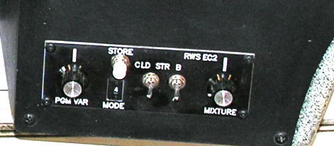
Bob...in the center of the ECU control panel are 2 toggle switches...the one at right toggles between "A" and "B"...the "A" is hidden by the switch...using the LCD screen for the EMS, the ECU is programmable from the cockpit...Fred
[img]cid:EABF179C-5720-4B18-AC4E-8FB026BA1FC5[/img]
[img]cid:DE63BB4E-74F4-470B-89D4-2E0B3205093D[/img]
| | - The Matronics AeroElectric-List Email Forum - | | | Use the List Feature Navigator to browse the many List utilities available such as the Email Subscriptions page, Archive Search & Download, 7-Day Browse, Chat, FAQ, Photoshare, and much more:
http://www.matronics.com/Navigator?AeroElectric-List |
|
| Description: |
|
| Filesize: |
54.63 KB |
| Viewed: |
17731 Time(s) |
|
| Description: |
|
| Filesize: |
45.38 KB |
| Viewed: |
17731 Time(s) |
|
|
|
| Back to top |
|
|
user9253
Joined: 28 Mar 2008
Posts: 1972
Location: Riley TWP Michigan
|
| Posted: Sat Oct 12, 2013 10:55 am Post subject: Re: EXP 2 Bus workaround |
|
|
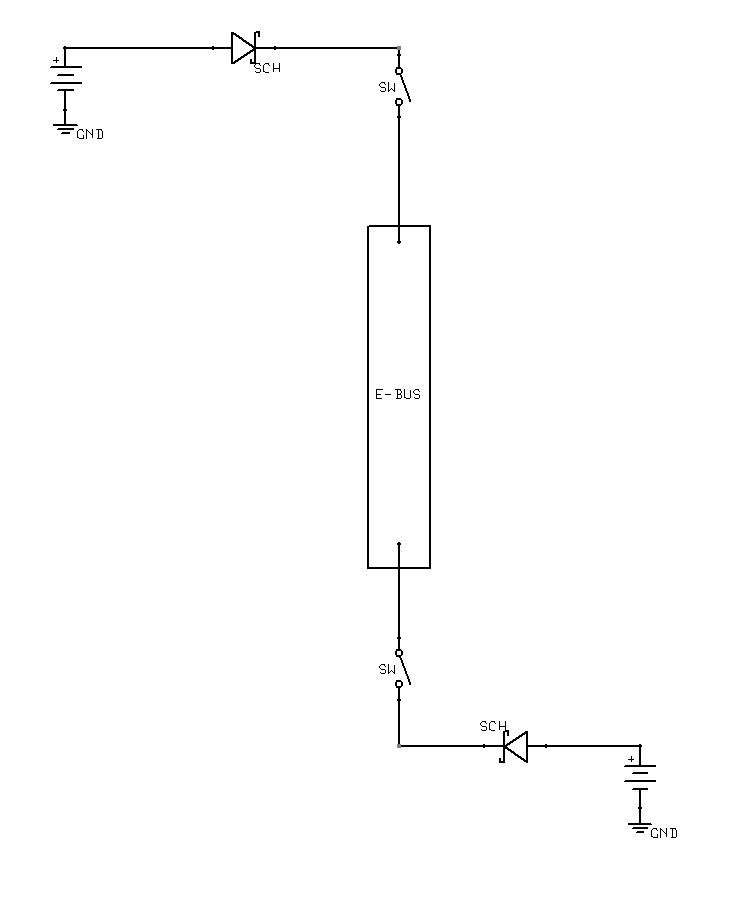
Assuming that the EXP 2 Bus is utilized, how about feeding the E-Bus from each end, one end from battery #1 and the other end from battery #2?  Then the failure of any one wire or connection will not open power going to the E-Bus.  30 amp fuses could be inserted near the batteries.  Diodes prevent starting or fault current from flowing from one battery to the other through the E-Bus.  See schematic attached.

Joe
| | - The Matronics AeroElectric-List Email Forum - | | | Use the List Feature Navigator to browse the many List utilities available such as the Email Subscriptions page, Archive Search & Download, 7-Day Browse, Chat, FAQ, Photoshare, and much more:
http://www.matronics.com/Navigator?AeroElectric-List |
|
| Description: |
|
| Filesize: |
29.02 KB |
| Viewed: |
17724 Time(s) |
|
_________________
Joe Gores |
|
| Back to top |
|
|
Fred Klein
Joined: 26 Mar 2012
Posts: 503
|
| Posted: Sat Oct 12, 2013 11:15 am Post subject: EXP 2 Bus workaround |
|
|
On Oct 12, 2013, at 11:55 AM, user9253 wrote:
| Quote: | | Assuming that the EXP 2 Bus is utilized, how about feeding the E-Bus from each end, one end from battery #1 and the other end from battery #2? |
Thanks Joe...by coincidence, I've just sent off an email to the makers of the EXP asking almost the very same thing...stay tuned, Fred
[quote][b]
| | - The Matronics AeroElectric-List Email Forum - | | | Use the List Feature Navigator to browse the many List utilities available such as the Email Subscriptions page, Archive Search & Download, 7-Day Browse, Chat, FAQ, Photoshare, and much more:
http://www.matronics.com/Navigator?AeroElectric-List |
|
|
|
| Back to top |
|
|
Fred Klein
Joined: 26 Mar 2012
Posts: 503
|
| Posted: Sat Oct 12, 2013 12:03 pm Post subject: EXP 2 Bus workaround |
|
|
On Oct 12, 2013, at 8:43 AM, Robert L. Nuckolls, III wrote:
| Quote: | - independent back up battery for Skyview,
- independent back up battery for stand-alone GPS, Garmin 396,
With two fat batteries on board, backing up these items
with still more batteries seems excessively 'redundant'.
If the ship's batteries are depleted, the value
of having the panel lit seems contrary to the
purpose of having an 'endurance mode' of flight.
|
Bob...my reasoning behind the individual little back up batteries for Skyview EFIS and my back up GPS was not to address an immediate concern for main battery life, but rather to provide continued operation independent of the aircraft electrical system, be it powered by the "main bus" or the "endurance bus".
On the other hand, I thought that given the degree of my engine's dependence on electricity, it would be a good thing to lessen the load going thru the endurance bus...I've yet to quantify the implications of this, but conceptually, I thought it was a good move.
No question in my mind that I want to incorporate a robust endurance bus...a couple of years ago, a Europa pal, Paul McCallister, was struck by lightning, and continued flying for 90 minutes to your design which he'd followed which included an endurance bus as part of your Rotax 9XX diagram.
Fred
[quote][b]
| | - The Matronics AeroElectric-List Email Forum - | | | Use the List Feature Navigator to browse the many List utilities available such as the Email Subscriptions page, Archive Search & Download, 7-Day Browse, Chat, FAQ, Photoshare, and much more:
http://www.matronics.com/Navigator?AeroElectric-List |
|
|
|
| Back to top |
|
|
peter(at)sportingaero.com
Guest
|
| Posted: Sat Oct 12, 2013 12:11 pm Post subject: EXP 2 Bus workaround |
|
|
Fred,
I had an Exp Bus 2 in my airplane for several years. The original builder fitted it after a similar thought process to your friend's. Thinking about its good points and not so good.
Good things:
It has a good instrument light dimmer
Not so good things:
It is difficult to expand
The current sensing lights on the indicator module aren't that accurate (cause more concern than they are worth)
It is difficult to add additional services
I found I had an intermittent fault that cut power to the avionics momentarily, which took the txpdr off line for long enough that ATC would give me a hard time, but I could not talk back to them as the radio was going through its self test. Never did find out what the problem was.
I would use it to power those items that you could fly without.
I would route the power to the ECUs well away from it (for that matter, anything to do with the engine/fuel pumps) and would also power the radio, txpdr & Skyview from the Endurance bus only (with 2 batteries you don't really need a skyview battery as well).
I would have an individual switch to connect each battery to the endurance bus (one switch is a single point failure), and an individual switch for each fuel pump - perhaps gated to stop inadvertent switching off.
If comm, txpdr & Skyview remain powered from Av bus on Exp2 I would not use the avionics master switch on the board (another potential single point failure) - can it be jumpered? If it only powers the GPS (with internal battery) & intercom there is not much point in a jumper, leave it in.
Peter
On 12/10/2013 07:29, Fred Klein wrote:
[quote] | Quote: | Guys...electrical wizards...
With full knowledge of my ignorance of all things electric but with only scant knowledge of the challenges which lay ahead, some time ago I purchased an EXP 2 Bus, thinking that having one would simplify many issues and offset some of the novelty inherent with my auto engine conversion, a MPEFIed derivative of a EA81 Subaru built by RAM Performance Aero Engines which is liquid cooled. Aircraft is a Europa XS monowheel which is typically powered w/ a 912S or 914.
I've been struggling to layout a circuit diagram which combines the EXP 2 BUS configured for an external solenoid with the dual battery / single alternator diagram Z-19 in the "Connection".
I have made a number of decisions which have committed me to the digital world including:
- an engine w/ electronic ignition, fuel injection, and an ECU (EC3, Real World Systems) which came w/ the engine,
- a digital EMS (EM3, Real World Systems) which "talks" w/ the ECU,
- a digital EFIS (Skyview) including moving map, digital terrain, Transponder, COM, and Intercom.
By selecting an auto engine conversion, I have committed to:
- one alternator, belt driven,
- one coolant pump, belt driven,
- single spark plug in each cylinder.
Additionally, in order to provide redundancy, the engine and control system includes:
- dual batteries, presently planned to be Odyssey 680's,
- two independent high pressure fuel pumps, each w/ their own filter,
- independent back up battery for Skyview,
- independent back up battery for stand-alone GPS, Garmin 396,
- redundant motherboards (A and B) for the ECU which are toggled from the panel.
OK...about the EXP BUS...I've now read many reports (including the VAF threads) which point out its shortcomings...but having spent $550 for it and its companion Indicator Module, and given my inexperience and lack of knowledge of things electrical, I still believe it has a place in my panel, so I hope any critique of what I'm up to doesn't focus on simply getting rid of it.
The main problem I'm having with the EXP BUS is that it simply does not have the two 20 amp circuits my engine guy sez are essential...one for the fuel injectors, and one for the coils. On my circuit diagram, I attempt to address it by running those two circuits off an Endurance bus which avoids the EXP BUS entirely.
I do use available circuits in the EXP BUS for the ECU, the EMS, and the fuel pumps; these components are also fed from the Endurance bus.
I have space on my panel (just above the EXP BUS, and below the Skyview flat screen) for a row of 6 - CB / switches which are presently planned to be:
- rocker or toggle between Fuel Pump #1 and Fuel Pump #2,
- Endurance Master Switch / 50 amp CB,
- Battery #2 ON / OFF,
- 20 amp CB for Fuel Injectors,
- 20 amp CB for Coils,
- spare
Attached are pixs of my instrument panel in its present state, and a proposed circuit diagram.
I'd be most appreciative of any comments, and particularly those which point our errors or weakness in the diagram.
Fred
|
[b]
| | - The Matronics AeroElectric-List Email Forum - | | | Use the List Feature Navigator to browse the many List utilities available such as the Email Subscriptions page, Archive Search & Download, 7-Day Browse, Chat, FAQ, Photoshare, and much more:
http://www.matronics.com/Navigator?AeroElectric-List |
|
|
|
| Back to top |
|
|
Fred Klein
Joined: 26 Mar 2012
Posts: 503
|
| Posted: Sat Oct 12, 2013 12:51 pm Post subject: EXP 2 Bus workaround |
|
|
On Oct 12, 2013, at 1:11 PM, Peter Pengilly wrote:
| Quote: | I had an Exp Bus 2 in my airplane for several years. The original builder fitted it after a similar thought process to your friend's. Thinking about its good points and not so good.
Good things:
It has a good instrument light dimmer
|
Peter...what a ringing endorsement...!...LOL...
Thanks much for your thoughtful suggestions...I am indeed back at the drawing board.
Fred
[quote][b]
| | - The Matronics AeroElectric-List Email Forum - | | | Use the List Feature Navigator to browse the many List utilities available such as the Email Subscriptions page, Archive Search & Download, 7-Day Browse, Chat, FAQ, Photoshare, and much more:
http://www.matronics.com/Navigator?AeroElectric-List |
|
|
|
| Back to top |
|
|
nuckolls.bob(at)aeroelect
Guest
|
| Posted: Sun Oct 13, 2013 6:41 am Post subject: EXP 2 Bus workaround |
|
|
| Quote: |
Bob...my reasoning behind the individual little back up batteries
for Skyview EFIS and my back up GPS was not to address an immediate
concern for main battery life, but rather to provide continued
operation independent of the aircraft electrical system, be it
powered by the "main bus" or the "endurance bus".
|
Yes, that's what backup batteries do . . .
| Quote: | On the other hand, I thought that given the degree of my engine's
dependence on electricity, it would be a good thing to lessen the
load going thru the endurance bus...I've yet to quantify
the implications of this, but conceptually, I thought it was a good move.
|
In a two-battery system, the engine never sees
the endurance bus; in a one-battery system, ditto.
The engine should run from a battery bus, preferably
one dedicated to the task.
| Quote: | No question in my mind that I want to incorporate a robust endurance
bus...a couple of years ago, a Europa pal, Paul McCallister, was
struck by lightning, and continued flying for 90 minutes to your
design which he'd followed which included an endurance bus as part
of your Rotax 9XX diagram.
|
90 minutes . . . that's the first NUMBER that
has popped up in this discussion. Last week we had
some conversation here on the List with a fellow
who was going through much of the same questions
you are now . . . but with no answers based on
analysis and preventative maintenance as opposed
to "good moves".
The point being that the elegant system design
starts with energy budgets . . . we had some
discussion here on the List about the Dreaded
Downwind Turn and I promised to finish an
article on the topic. That problem also yields
to an analysis that identifies, quantifies and
then distributes a finite amount of energy to
a series of activities that produce the desired
end goal.
The outcome of that analysis promises to dispel
useless if not dangerous myths and gives us
opportunity to be better pilots based on the
numbers.
I used to occupy a booth at OSH right across
the isle from the guy selling EXP-Bus . . . or
something similar . . . I don't recall now. That
was 20 years ago. But I could hear his 'pitch'.
Even at that stage of advancement in my career,
I had to cringe at some of the superlatives
he used first to hook then reel in a prospective
customer. The word "emergency" was used with some
frequency along with claims for automation, labor
reduction, cost reduction, etc. etc. . . . all
GOOD things. But not once did he speak to sizing
batteries, alternators and particularly ARCHITECTURE
to a task, then knowing what the limits were for
expecting that task to terminate comfortably.
After all, he didn't sell alternators or batteries
(we were doing that across the isle). He was selling
architecture . . . and if he had any notion of how
is cookie-cutter architecture would tie the hands
of his customer's design process . . . that was not
part of the 'pitch.'
When we learn to fly, we're encourage to know, use
and respect numbers for Vx, Vy, Best Glide, Vne,
Stall Clean, Stall Dirty, Flap and gear extension
speeds, C.G., weight, mixture, manifold pressures,
increased drag in a turn, . . . all those numbers spread out
across the panel. But my instructor never mentioned
the value of KNOWING just how long I could fly
battery only and MAINTAINING that capability through
design and preventative maintenance.
For my instructor, the BEST notion for detecting
alternator failure was to pick up on the ammeter
reading . . . yeah, we all scan that thing, right?
For him, first notice that the alternator was dead
triggered an emergency situation . . . because he
wasn't sure how long it had been dead and he had
not the foggiest notion of how many minutes of
battery-only endurance was available. The best he
could hope for is to extend an unknown number by
turning off switches and pulling breakers . . .
in-flight systems analysis when the pilot SHOULD be
flying and navigating. It's the stuff from which
really good dark-n-stormy-night stories are
made.
I'll suggest that the EXP-Bus offers at most
a challenge for working around some relatively
minor architecture issues. But like the guy
who sits down to design a new airplane, we're
wrestling with the same quest for setting
design goals and then meeting them based on
the numbers.
The first number that would be of interest to
me in your airplane is how long can I run this
engine on a battery that who's service life is
25% used up? The next number is to deduce the
time you can run a minimalist list of electro-
whizzies that will get you to a comfortable
arrival . . . if not at your original destination
at least some place with convenient maintenance
services . . . not at Dead Cow International
50 miles from everywhere else.
The guy who sold you the engine should KNOW
how much energy it takes to run his product.
Not recommended wire or breaker size but WATTS
of total power consumption at full throttle . . .
and if draw is RPM dependent, then current
demands at throttle settings for maximum
endurance as well. Knowing those numbers at
both normal (14.6v) and end of battery life
(10.5v) would be required if I were designing
a TC aircraft . . . but no less important in
the OBAM aircraft.
These are the functional equivalents of "Vx, Vy
and Best Glide" numbers for your engine . . .
numbers a flight instructor would never be
expected to know but of intense interest to
somebody in your position.
A backup battery is a band-aid for not KNOWING
the capabilities of and demands on the main
battery. This is a kind of confession for saying
that while we can FLY the airplane with due
diligence to Vx, Vy and Best Glide . . . but
ignorant of battery-only endurance for the
engine or other accessories. Features necessary
us to demonstrate our skills as pilots.
My suggestion is to see how we can do a minimalist
effort to incorporate the EXP-Bus into something
like Z-19. Those are things we can discuss here
on the List because they deal with the architecture.
But whether or not you can toss out the notion of
'backup batteries' depends on your acquiring good
numbers and then folding those numbers into your
POH with as much confidence as you have for putting
the wheels down when and where you wanted them every
time.
QUESTION: Is there any value in having separate,
independent controls for ECU, Pumps and/or Ignition
in planning the partition between normal flight and
Plan-B? In other words, could Plan-A and Plan-B
configurations be controlled by a single switch?
In other words, let us consider switches. Under what
conditions would you want to turn any one thing ON
or OFF independently of other switches . . . or can
we combine functionality much like that which happens
when you turn the key in your car?
Bob . . .
| | - The Matronics AeroElectric-List Email Forum - | | | Use the List Feature Navigator to browse the many List utilities available such as the Email Subscriptions page, Archive Search & Download, 7-Day Browse, Chat, FAQ, Photoshare, and much more:
http://www.matronics.com/Navigator?AeroElectric-List |
|
|
|
| Back to top |
|
|
nuckolls.bob(at)aeroelect
Guest
|
| Posted: Sun Oct 13, 2013 10:31 am Post subject: EXP 2 Bus workaround |
|
|
| Quote: | 90 minutes . . . that's the first NUMBER that
has popped up in this discussion. Last week we had
some conversation here on the List with a fellow
who was going through much of the same questions
you are now . . . but with no answers based on
analysis and preventative maintenance as opposed
to "good moves".
|
Some bullet points to touch on in the quest
for an elegant solution:
(1) See if the present avionics bus and it's associated
master switch can be re-configured for the master switch
to become an e-bus alternate feed switch by taking
the upstream-end of that switch to a fuse on the main
battery bus. Then jeep some flying leads onto the EXP-Bus
assembly to add a diode feed from the Main bus to the
new E-Bus.
(2) Explore the value of an Engine Bus Option A
and an Engine Bus Option B . . . an organization
of normal and standby engine loads that can be
controlled by a switch dedicated to each option. (a) Determine whether or not it is unhealthy or dangerous for both busses to be powered at the same time.
(b) If so, what kind of mechanism would allowing either option to be selected OFF or ON indiviudally but never simultaneously. (c) Conduct a failure modes effects analysis to
deduce the single point failure items for engine
operation.
(3) Get real life numbers on the power required to
power either of these options.
(4) Consider bringing the alternator B-Lead to a stud on
a fire wall mounted contactor.
Answer to (2) will drive further suggestions for
eliminating a number of switches and improving on
the probability for smooth conversion of a failure
event to be no-big-deal.
Bob . . . [quote][b]
| | - The Matronics AeroElectric-List Email Forum - | | | Use the List Feature Navigator to browse the many List utilities available such as the Email Subscriptions page, Archive Search & Download, 7-Day Browse, Chat, FAQ, Photoshare, and much more:
http://www.matronics.com/Navigator?AeroElectric-List |
|
|
|
| Back to top |
|
|
Fred Klein
Joined: 26 Mar 2012
Posts: 503
|
| Posted: Sun Oct 13, 2013 10:54 am Post subject: EXP 2 Bus workaround |
|
|
Bob...thank you so much for your continued assistance in sorting out my ship's electrical issues...I have some unrelated things to do today, but will continue this conversation tomorrow after I've been able to quantify at least some of the considerations you've raised...and if it makes sense to throw the EXP Bus under the bus, I'm certainly willing to do so.
Cheers,
Fred
| Quote: | > 90 minutes . . . that's the first NUMBER that
> has popped up in this discussion. Last week we had
> some conversation here on the List with a fellow
> who was going through much of the same questions
> you are now . . . but with no answers based on
> analysis and preventative maintenance as opposed
> to "good moves".
Some bullet points to touch on in the quest
for an elegant solution:
|
| | - The Matronics AeroElectric-List Email Forum - | | | Use the List Feature Navigator to browse the many List utilities available such as the Email Subscriptions page, Archive Search & Download, 7-Day Browse, Chat, FAQ, Photoshare, and much more:
http://www.matronics.com/Navigator?AeroElectric-List |
|
|
|
| Back to top |
|
|
Fred Klein
Joined: 26 Mar 2012
Posts: 503
|
| Posted: Sun Oct 13, 2013 11:26 am Post subject: EXP 2 Bus workaround |
|
|
On Oct 13, 2013, at 7:40 AM, Robert L. Nuckolls, III wrote:
| Quote: | The engine should run from a battery bus, preferably
one dedicated to the task.
|
Bob...I accept this without reservation...and I regret that in my attempts to work out a scheme which put my EPS Bus to good use and honored the concepts embedded in your Z-19 resulted in a circuit diagram which led me so far astray from this concept.
As I study Z-19, I'm noting the multiple busses fed from the two battery contactors and the nominal sizing of the wires (12 AWG, w/ the caveat that they be no longer than 6 inches) to the 2 battery busses.
I will determine the connected load on each of 2 battery busses which would be devoted to keeping the engine running...(fuel pumps, ECU, fuel injectors, coils) and the required size of their feeders.
Feeding these multiple busses w/ my 2 batteries in the tailcone seems problematic if the contactors are adjacent to the batteries. I'd queried you a while back about the implications of mounting the contactors on the fire wall w/ the batteries in the rear...about 10 feet away...you mentioned this is not common practice and (I believe you said that) it poses unwanted risks.
Can those risks be mitigated by some kind of fusible links back at the batteries?...or is it just plainly a dumb idea to separate bat from contactor?
Would not the feeders to the (hot) battery busses carry the same risks?
Fred
[quote][b]
| | - The Matronics AeroElectric-List Email Forum - | | | Use the List Feature Navigator to browse the many List utilities available such as the Email Subscriptions page, Archive Search & Download, 7-Day Browse, Chat, FAQ, Photoshare, and much more:
http://www.matronics.com/Navigator?AeroElectric-List |
|
|
|
| Back to top |
|
|
nuckolls.bob(at)aeroelect
Guest
|
| Posted: Sun Oct 13, 2013 1:51 pm Post subject: EXP 2 Bus workaround |
|
|
At 01:53 PM 10/13/2013, you wrote:
| Quote: | --> AeroElectric-List message posted by: Fred Klein <fklein(at)orcasonline.com>
Bob...thank you so much for your continued assistance in sorting out my ship's electrical issues...I have some unrelated things to do today, but will continue this conversation tomorrow after I've been able to quantify at least some of the considerations you've raised...and if it makes sense to throw the EXP Bus under the bus, I'm certainly willing to do so. |
Let's not get too carried away . . . as
far as I know, the EXP-Bus performs as
advertised.
Many of its features could not be qualified
onto TC aircraft. Other features are just
plain awkward from a cost of ownership
perspective.
However, unlike other 'flashes in the
pan' of OBAM aviation history, the EXP-Bus is
still with us . . . and to my knowledge, it's not
set anyone's airplane on fire or played the
staring character in a dark-n-stormy night story.
The exercise for sifting of FMEA bits and
adding up all the numbers is 90% common to
any other suite of hardware. So before we
abandon the $time$ you already have invested,
let's consider ways to round off the rough
edges without pushing your fly-date out
unnecessarily.
By the way, does anyone on the List have an
EXP-Bus 2 that is un-installed that they
could photograph from all perspectives to
share with the List? Don't need pictures
of the remote boxes . . . just the power
distribution and switching assembly.
Fred, your lighting and image quality was
excellent but this view . . .
[img]cid:.0[/img]
is a bit cluttered in the foreground. I'd liked to see
how this puppy is assembled and wired . . . If anyone
is taking new pictures, avoid flash and/or direct lighting,
sky-light shaded from direct sun provides excellent, shadow
and high-light free illumination for illustrating the deeper
secrets.
No hurry, we don't have a dragon to slay. I need to
spend some time on Carlos' V-Power system integration
questions.
Bob . . .
| | - The Matronics AeroElectric-List Email Forum - | | | Use the List Feature Navigator to browse the many List utilities available such as the Email Subscriptions page, Archive Search & Download, 7-Day Browse, Chat, FAQ, Photoshare, and much more:
http://www.matronics.com/Navigator?AeroElectric-List |
|
| Description: |
|
| Filesize: |
180.41 KB |
| Viewed: |
17673 Time(s) |
|
|
|
| Back to top |
|
|
|
|
You cannot post new topics in this forum
You cannot reply to topics in this forum
You cannot edit your posts in this forum
You cannot delete your posts in this forum
You cannot vote in polls in this forum
You cannot attach files in this forum
You can download files in this forum
|
Powered by phpBB © 2001, 2005 phpBB Group
|

