 |
Matronics Email Lists
Web Forum Interface to the Matronics Email Lists
|
| View previous topic :: View next topic |
| Author |
Message |
user9253
Joined: 28 Mar 2008
Posts: 1972
Location: Riley TWP Michigan
|
 Posted: Sun Nov 10, 2013 5:59 am Post subject: Minimizing audio interference Posted: Sun Nov 10, 2013 5:59 am Post subject: Minimizing audio interference |
 |
|
I was going to post on VansAirforce in a thread about audio strobe noise, but decided to post here first to make sure that my post is accurate and correct.  Let me know if it's not.

Thanks, Joe


Whenever current from separate loads shares the same conductor (wire or metal airframe), the current from one load can affect the current from another load.  The interference can be minimized by:

1. Keeping the shared conductors as short as possible

2. Increasing the wire size of the shared conductor

3. Do not share a conductor with more than one load.

4. Keep the positive and negative conductors of the offending circuit together and twisted.

 If the microphone jack is not isolated from ground with insulating washers, then part of the mic current flows though the airframe which also carries current from other aircraft loads.  This violates rule 3 above.  The mic circuit is especially vulnerable because its signal gets amplified.

  If the strobe uses the airframe for the negative current path, this also violates rule 3 above.  It is better to power the strobe with twisted positive and negative wires instead of using the airframe for the negative conductor.
| | - The Matronics AeroElectric-List Email Forum - | | | Use the List Feature Navigator to browse the many List utilities available such as the Email Subscriptions page, Archive Search & Download, 7-Day Browse, Chat, FAQ, Photoshare, and much more:
http://www.matronics.com/Navigator?AeroElectric-List |
|
_________________
Joe Gores |
|
| Back to top |
|
 |
nuckolls.bob(at)aeroelect
Guest
|
| Posted: Sun Nov 10, 2013 8:01 am Post subject: Minimizing audio interference |
|
|
At 07:59 AM 11/10/2013, you wrote:


I was going to post on VansAirforce in a thread about audio strobe

noise, but decided to post here first to make sure that my post is

accurate and correct.  Let me know if it's not.

Thanks, Joe


Whenever current from separate loads shares the same conductor (wire

or metal airframe), the current from one load can affect the current

from another load.  The interference can be minimized by:

1. Keeping the shared conductors as short as possible


    Generally speaking, the only conductors that

    might be shared by an antagonist and potential

    victim are grounds . . . and grounding a victim

    onto a location already polluted with antagonistic

    perturbations is easily avoided with attention to

    the architecture of the ground system. See Figure Z-15


2. Increasing the wire size of the shared conductor


    Better yet . . . do not share . . .


3. Do not share a conductor with more than one load.


    . . . high on the list of design goals for the

    elegantly crafted airframe.


4. Keep the positive and negative conductors of the offending circuit

together and twisted.


    Twisting speaks to magnetic coupling between antagonistic

    stimulus and potential victims. This coupling mode is

    weak. Further, it's unlikely that one finds it mechanically

    advantageous to route the wires for antagonists (generally

    airframe bundles) along with wires belonging to potential

    victims . . . generally situated on the panel.


  If the microphone jack is not isolated from ground with insulating

washers, then part of the mic current flows though the airframe which

also carries current from other aircraft loads.  This violates rule 3

above.  The mic circuit is especially vulnerable because its signal

gets amplified.


    Yes


If the strobe uses the airframe for the negative current path, this

also violates rule 3 above.  It is better to power the strobe with

twisted positive and negative wires instead of using the airframe for

the negative conductor.


    Not a great sin . . . the BIG guys ground nasty

    loads to airframes all the time. It's easy to craft

    TWO ground systems wherein the second is attentive to

    risks to potential victims.


    Noises from strobe systems heard on headphones and/or

    transmitted signals are almost always conducted by

    virtue of poor grounding choices for audio system

    wiring and rarely, radiated noises from strobe tubes into

    the co-located antennas. Wingtip mounted comm and vor antennas

    share this risk.


    Some avionics not designed in the spirit and intent

    of DO160 suggestions for immunity to bus noises may

    also exhibit vulnerability to strobes or other sources.

    This condition calls for adding filters to the victim's

    14v supply.

   Bob . . .
| | - The Matronics AeroElectric-List Email Forum - | | | Use the List Feature Navigator to browse the many List utilities available such as the Email Subscriptions page, Archive Search & Download, 7-Day Browse, Chat, FAQ, Photoshare, and much more:
http://www.matronics.com/Navigator?AeroElectric-List |
|
|
|
| Back to top |
|
|
mrspudandcompany(at)veriz
Guest
|
| Posted: Sun Nov 10, 2013 8:53 am Post subject: Minimizing audio interference |
|
|
| Quote: | 3. Do not share a conductor with more than one load.
. . . high on the list of design goals for the
elegantly crafted airframe.
|
Am I right in assuming that this refers to properly
fused wires from one of the busses and does not
include the fat wires wich carry most if not all the
loads in the aircraft.
Roger
--
Do you have a slow PC? Try a Free scan http://www.spamfighter.com/SLOW-PCfighter?cid=sigen
| | - The Matronics AeroElectric-List Email Forum - | | | Use the List Feature Navigator to browse the many List utilities available such as the Email Subscriptions page, Archive Search & Download, 7-Day Browse, Chat, FAQ, Photoshare, and much more:
http://www.matronics.com/Navigator?AeroElectric-List |
|
|
|
| Back to top |
|
|
nuckolls.bob(at)aeroelect
Guest
|
| Posted: Sun Nov 10, 2013 11:17 am Post subject: Minimizing audio interference |
|
|
At 10:52 AM 11/10/2013, you wrote:


<mrspudandcompany(at)verizon.net>


3. Do not share a conductor with more than one load.

    . . . high on the list of design goals for the

    elegantly crafted airframe.

        Am I right in assuming that this refers to

properly        fused wires from one of the busses and does

not        include the fat wires wich carry most if not all

the        loads in the aircraft.

     Obviously, everything in the airplane

     requiring power and ground will have

     a lot of conductors in common.


     It's known that some accessories tend to

     be antagonists (high currents, noisy,

     trashy voltage transients, strong RF

     emitters, etc.) while other things tend

     to be potential victims (stuff that processes

     tiny signals).


     We're getting off into the weeds with the

     'shared conductors' terminology. When it comes

     to power distribution, all things

     electric 'share' conductors with each other.

     DO-160 or similar qualification protocols suggest

     means by which the most vulnerable of victims

     can get power from the noisiest of busses with

     little risk of difficulty.


     99% of noise problems are founded on

     a very limited range of installation issues

     NONE of which have to do with twisting feeders,

     co-location of coax cables in wire bundles,

     or failure to include any sort of 'filter' on

     either a victim or antagonist . . .


     We've discussed the high order probabilities for

     noise in either transmitted or received signals

     when victim grounds that should be centralized

     on the panel get tied down somewhere else.


     A second order risk is seen when levels of

     transmitted RF rise to unusual levels in the

     vicinity of tha panel. This condition can present

     when the antenna is too close to the equipment

     installed . . . or a coax shield has detached

     in a connector causing the entire feedline to

     become a radiator.


     "Shared conductors" is not a good way to talk

     about a noise issue. You have a victim, an

     antagonist and a PROPAGATION MODE. Breaking

     the propagation mode is the path to noise-free

     Nirvana.


   Bob . . .
| | - The Matronics AeroElectric-List Email Forum - | | | Use the List Feature Navigator to browse the many List utilities available such as the Email Subscriptions page, Archive Search & Download, 7-Day Browse, Chat, FAQ, Photoshare, and much more:
http://www.matronics.com/Navigator?AeroElectric-List |
|
|
|
| Back to top |
|
|
user9253
Joined: 28 Mar 2008
Posts: 1972
Location: Riley TWP Michigan
|
| Posted: Sun Nov 10, 2013 7:46 pm Post subject: Re: Minimizing audio interference |
|
|
| Quote: | "Shared conductors" is not a good way to talk
about a noise issue. |
What if we say that audio signals should not share conductors with other loads? An audio signal is unlikely to share a positive 12 volt wire. But many audio signals use ground as a common path in their circuit. A problem arises when other loads share the same ground conductor as the audio circuit.
Joe
| | - The Matronics AeroElectric-List Email Forum - | | | Use the List Feature Navigator to browse the many List utilities available such as the Email Subscriptions page, Archive Search & Download, 7-Day Browse, Chat, FAQ, Photoshare, and much more:
http://www.matronics.com/Navigator?AeroElectric-List |
|
_________________
Joe Gores |
|
| Back to top |
|
|
nuckolls.bob(at)aeroelect
Guest
|
| Posted: Sun Nov 10, 2013 8:27 pm Post subject: Minimizing audio interference |
|
|
At 09:46 PM 11/10/2013, you wrote:
| Quote: | --> AeroElectric-List message posted by: "user9253" <fransew(at)gmail.com>
> "Shared conductors" is not a good way to talk
> about a noise issue.
What if we say that audio signals should not share conductors with other loads? An audio signal is unlikely to share a positive 12 volt wire. But many audio signals use ground as a common path in their circuit. A problem arises when other loads share the same ground conductor as the audio circuit.
Joe |
"Audio signals" are not "loads". All devices
in the airplane share a common 12v supply bus.
Eventually, ALL grounds come together too.
Study up on the 'ground loop' phenomenon illustrated
in part here.
http://tinyurl.com/6w87rvb
The design task is to re-ground those devices
marked
[img]cid:.0[/img]
such that their shared grounds do not inject
noises. Everybody needs a ground that's
ultimately common with all other grounds.
It's WHERE the grounds are placed and
how they come together that produces the
recipe for success.
In the targets we used to build at Beech
there were three ground systems. Power,
analog and digital. Just as everything
comes to ground at the forest of tabs in
Figure Z-15, so too did all the grounds
in the target come to a common point in the
power distribution box . . . but what happened
to them along the way determines their
probability of offering in ingress point
for noise into a potential victim.
Bob . . .
Bob . . .
| | - The Matronics AeroElectric-List Email Forum - | | | Use the List Feature Navigator to browse the many List utilities available such as the Email Subscriptions page, Archive Search & Download, 7-Day Browse, Chat, FAQ, Photoshare, and much more:
http://www.matronics.com/Navigator?AeroElectric-List |
|
| Description: |
|
| Filesize: |
8.57 KB |
| Viewed: |
8334 Time(s) |

|
|
|
| Back to top |
|
|
user9253
Joined: 28 Mar 2008
Posts: 1972
Location: Riley TWP Michigan
|
| Posted: Mon Nov 11, 2013 6:30 am Post subject: Re: Minimizing audio interference |
|
|
I like it that Z15-3.1 shows not only the right way, but also the wrong way to ground devices.  I understand that earphones and microphones should not be grounded locally, but should only be grounded at the panel end (intercom or radio).

  I am a little confused with the engine sensors.  Grounding might be different for different types of sensors and their display (EMS or steam gauge).  Some sensors are grounded automatically by nature of their construction and mounting.  But for sensors that have isolated ground, I assume that the ground  wire should terminate at the EMS or display device and not at the engine case.  Of course always follow the manufactures installation instructions.

Joe
| | - The Matronics AeroElectric-List Email Forum - | | | Use the List Feature Navigator to browse the many List utilities available such as the Email Subscriptions page, Archive Search & Download, 7-Day Browse, Chat, FAQ, Photoshare, and much more:
http://www.matronics.com/Navigator?AeroElectric-List |
|
_________________
Joe Gores |
|
| Back to top |
|
|
nuckolls.bob(at)aeroelect
Guest
|
| Posted: Mon Nov 11, 2013 11:07 am Post subject: Minimizing audio interference |
|
|
At 08:30 AM 11/11/2013, you wrote:
| Quote: | --> AeroElectric-List message posted by: "user9253" <fransew(at)gmail.com>
I like it that Z15-3.1 shows not only the right way, but also the wrong way to ground devices. I understand that earphones and microphones should not be grounded locally, but should only be grounded at the panel end (intercom or radio).
I am a little confused with the engine sensors. Grounding might be different for different types of sensors and their display (EMS or steam gauge). Some sensors are grounded automatically by nature of their construction and mounting. |
Yes. Many oil pressure, oil temperature, CHT, EGT sensors are
guilty of 'local grounding' . . . and for the manner in which they
were originally intended to be used . . . it didnt' matter.
| Quote: | | But for sensors that have isolated ground, I assume that the ground wire should terminate at the EMS or display device and not at the engine case. Of course always follow the manufactures installation instructions. |
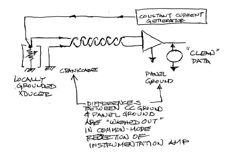
Oh, absolutely. But absent a end-to-end design goal,
one has to play the DIY integration game. One useful
way to deal with a locally grounded signal source
looks like this:
[img]cid:.0[/img]
There are low cost integrated circuits that do the
task of making remote voltage measurements across
hostile environments. Alternatively, one can take all
grounds for the instrument to the crankcase. The same
game is played in audio systems. I did the specification
for design of an intercom system on the Lears that
coupled all stations together by way of a transformer
coupled, twisted pair . . . Intercoms scattered about
the airplane could be grounded locally for power and
control without the worry of noises on the ground-
differences finding their way into the audio.
Bob . . .
| | - The Matronics AeroElectric-List Email Forum - | | | Use the List Feature Navigator to browse the many List utilities available such as the Email Subscriptions page, Archive Search & Download, 7-Day Browse, Chat, FAQ, Photoshare, and much more:
http://www.matronics.com/Navigator?AeroElectric-List |
|
| Description: |
|
| Filesize: |
123.9 KB |
| Viewed: |
8301 Time(s) |

|
|
|
| Back to top |
|
|
bob.verwey(at)gmail.com
Guest
|
| Posted: Mon Nov 11, 2013 11:44 pm Post subject: Minimizing audio interference |
|
|
Bob N, for us neophytes, please enlighten us on the triangular device in your sketch.
Best...
Bob Verwey
IO 470 A35 Bonanza ZU-DLW
On 11 November 2013 21:05, Robert L. Nuckolls, III <nuckolls.bob(at)aeroelectric.com (nuckolls.bob(at)aeroelectric.com)> wrote:
| Quote: | At 08:30 AM 11/11/2013, you wrote:
| Quote: | --> AeroElectric-List message posted by: "user9253" <fransew(at)gmail.com (fransew(at)gmail.com)>
I like it that Z15-3.1 shows not only the right way, but also the wrong way to ground devices. I understand that earphones and microphones should not be grounded locally, but should only be grounded at the panel end (intercom or radio).
I am a little confused with the engine sensors. Grounding might be different for different types of sensors and their display (EMS or steam gauge). Some sensors are grounded automatically by nature of their construction and mounting. |
Yes. Many oil pressure, oil temperature, CHT, EGT sensors are
guilty of 'local grounding' . . . and for the manner in which they
were originally intended to be used . . . it didnt' matter.
| Quote: | | But for sensors that have isolated ground, I assume that the ground wire should terminate at the EMS or display device and not at the engine case. Of course always follow the manufactures installation instructions. |
Oh, absolutely. But absent a end-to-end design goal,
one has to play the DIY integration game. One useful
way to deal with a locally grounded signal source
looks like this:
[img]cid:.0[/img]
There are low cost integrated circuits that do the
task of making remote voltage measurements across
hostile environments. Alternatively, one can take all
grounds for the instrument to the crankcase. The same
game is played in audio systems. I did the specification
for design of an intercom system on the Lears that
coupled all stations together by way of a transformer
coupled, twisted pair . . . Intercoms scattered about
the airplane could be grounded locally for power and
control without the worry of noises on the ground-
differences finding their way into the audio.
Bob . . .
|
| | - The Matronics AeroElectric-List Email Forum - | | | Use the List Feature Navigator to browse the many List utilities available such as the Email Subscriptions page, Archive Search & Download, 7-Day Browse, Chat, FAQ, Photoshare, and much more:
http://www.matronics.com/Navigator?AeroElectric-List |
|
| Description: |
|
| Filesize: |
123.9 KB |
| Viewed: |
8298 Time(s) |
|
|
|
| Back to top |
|
|
nuckolls.bob(at)aeroelect
Guest
|
| Posted: Tue Nov 12, 2013 7:29 am Post subject: Minimizing audio interference |
|
|
At 03:43 AM 11/12/2013, you wrote:
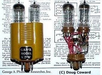
Jay is correct. The "operational amplifier" has a rich
history in the evolution of electronics. Check out
the articles on Wikipedia about George Philbrick,
Bob Widlar, Jim Williams, and Bob Pease just to
name a few of the colorful pioneers of the electronic
arts and sciences.
The op-amp comes in many flavors and sizes tailored
to a constellation of tasks. I cut my op-amp teeth about
1962 on this vacuum tube version that sold for a couple hundred
dollars in 2013 money . . .
[img]cid:.0[/img]

I doubt that there were more than a few dozen
products available.
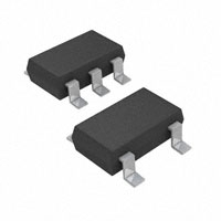
The last op-amp I stuck to a board looked like
a little brick of plastic about the size of a match
head . . .
[img]cid:.1[/img]
. . . and costs about $2. The Digikey site offers
over 30,000 variations on the theme. We've come
a long way baby . . .
Bob . . .
| | - The Matronics AeroElectric-List Email Forum - | | | Use the List Feature Navigator to browse the many List utilities available such as the Email Subscriptions page, Archive Search & Download, 7-Day Browse, Chat, FAQ, Photoshare, and much more:
http://www.matronics.com/Navigator?AeroElectric-List |
|
| Description: |
|
| Filesize: |
88.91 KB |
| Viewed: |
8293 Time(s) |
|
| Description: |
|
| Filesize: |
10.69 KB |
| Viewed: |
8293 Time(s) |
|
|
|
| Back to top |
|
|
|
|
You cannot post new topics in this forum
You cannot reply to topics in this forum
You cannot edit your posts in this forum
You cannot delete your posts in this forum
You cannot vote in polls in this forum
You cannot attach files in this forum
You can download files in this forum
|
Powered by phpBB © 2001, 2005 phpBB Group
|

