 |
Matronics Email Lists
Web Forum Interface to the Matronics Email Lists
|
| View previous topic :: View next topic |
| Author |
Message |
nuckolls.bob(at)aeroelect
Guest
|
 Posted: Wed Nov 27, 2013 9:25 am Post subject: kitfox /rotax 912 wiring diagram (variation on Z-16) Posted: Wed Nov 27, 2013 9:25 am Post subject: kitfox /rotax 912 wiring diagram (variation on Z-16) |
 |
|
At 08:41 AM 11/27/2013, you wrote:
--> AeroElectric-List message posted by: "user9253" <fransew(at)gmail.com>
Sacha,
I was looking at the wrong schematic, Kitfox Diagram 0.6.pdf, my mistake.
I should have been looking at Kitfox_Proposed_Diagram_1.23.pdf.
Even so, the dynamo output is still going though a 5 amp breaker. And the start switch is still on the control stick.
Joe
Joe offers some salient observations. I'm pleased that you've
taken a run at the AutoCAD flavored gauntlet!
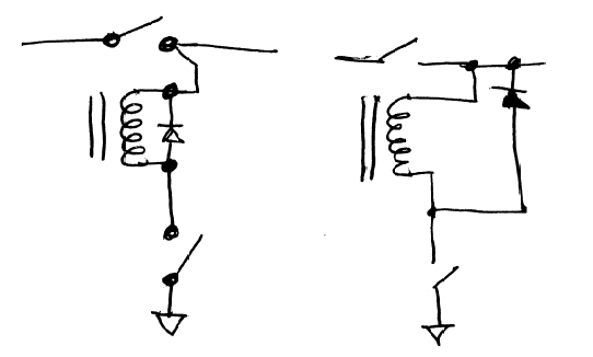
As you evolve your plan for this airplane, consider refining
your drawings to be less like schematics and more like wiring
diagrams. If you study the drawings I've posted you will discover
that they look more like the sketch on the left where the
END of each wire, i.e. the location of each termination is defined
both electrically and physically.
Schematics are entirely suited to describing how a
thing works but its a good idea to include information
on just how it all goes together too.
[img]cid:.0[/img]
Additional points of interest from your draft:
The battery bus is generally located very close to the
battery contactor. Feeder from the battery to battery
bus is short and no protection is necessary.
Your e-bus loads include a lot of stuff that seems
to go beyond the needs for en route, battery only
endurance. In other words, what is the minimalist
suite of electro-whizzies needed to navigate to
a point of destination airport in sight. After that,
your arrival in one piece is assured . . . you
can close the battery contactor and tax what ever
energy remains in the battery without adding to
your risks.
Consider re-assigning supply points for some
of the items on the avionics bus.
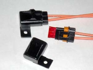
The breaker in the alternator b-lead can be
replaced with an in-line, fuse holder . . .
[img]cid:.1[/img]
and 30A fuse. The b-lead fuse can then
be located right next to the battery's
connection with the battery contactor.
The 5A "alternator breaker" is actually
a CONTROL breaker included to accommodate
the crowbar OV protection system.
Not sure stick-grip starter buttons are a good
idea . . . but if you do incorporate them
into the system, make sure your starter
contactor coil currents are not overly
antagonistic to the switches. As I outlined
in my essay on two-stage, starter-mounted
solenoids, the pull-in currents carried
buy the starter button are pretty scary . . .
hence the advice for a stand-alone, automotive
starter contactor with MUCH more benign
current draws . . . but even these are on
the order of 5A . . . and should probably
be wired with 20AWG wire to insure strong
pull-in. Contactors are most abused by soggy
pull-in current. More contactors have been
burned up by nearly dead batteries than by
healthy, fully charged batteries.
Recommend you use panel mounted, robust
button only and wire with 20AWG wire from
a protected feeder . . . you don't show a
'starter' breaker or fuse.
Looks like a great starting point . . . let's
continue to discuss its refinement.
Bob . . .
| | - The Matronics AeroElectric-List Email Forum - | | | Use the List Feature Navigator to browse the many List utilities available such as the Email Subscriptions page, Archive Search & Download, 7-Day Browse, Chat, FAQ, Photoshare, and much more:
http://www.matronics.com/Navigator?AeroElectric-List |
|
| Description: |
|
| Filesize: |
32.48 KB |
| Viewed: |
6667 Time(s) |
|
| Description: |
|
| Filesize: |
23.73 KB |
| Viewed: |
6667 Time(s) |

|
|
|
| Back to top |
|
 |
uuccio(at)gmail.com
Guest
|
| Posted: Thu Nov 28, 2013 2:12 pm Post subject: kitfox /rotax 912 wiring diagram (variation on Z-16) |
|
|
Joe and Bob,
Thanks a lot for your comments.
I'm pleased that you've taken a run at the AutoCAD flavored gauntlet!
Yup, it was worth it in the end… not just for my personal education, but also when you have to re-draw the same diagram several times.
As you evolve your plan for this airplane, consider refining
your drawings to be less like schematics and more like wiring
diagrams. If you study the drawings I've posted you will discover
that they look more like the sketch on the left where the
END of each wire, i.e. the location of each termination is defined
both electrically and physically.
Good point – it had occurred to me that that was a good idea but I haven’t got around to doing it yet.
The battery bus is generally located very close to the
battery contactor. Feeder from the battery to battery
bus is short and no protection is necessary.
OK, will remove the fuselink.
Your e-bus loads include a lot of stuff that seems
to go beyond the needs for en route, battery only
endurance. In other words, what is the minimalist
suite of electro-whizzies needed to navigate to
a point of destination airport in sight. After that,
your arrival in one piece is assured . . . you
can close the battery contactor and tax what ever
energy remains in the battery without adding to
your risks.
I thought about this a lot before I stuck all that stuff on the E-bus… strictly speaking I don’t need:
<![if !supportLists]>- <![endif]>Transponder/Alt encoder
<![if !supportLists]>- <![endif]>Autopilot
<![if !supportLists]>- <![endif]>AHRS
<![if !supportLists]>- <![endif]>Cigar Lighter 12V and USB supplies
But it’s nice to be able to have them (e.g. if you’re going to be landing in a field that’s new to you, you can have the A/P on while you look at the chart, etc), so I figured I would leave them there and turn them off if necessary (except for the AHRS but that only consumes 0.3A). Is this not advisable? (I’m a low time PPL so I’m completely open to suggestions in this area).
Consider re-assigning supply points for some
of the items on the avionics bus.
The breaker in the alternator b-lead can be
replaced with an in-line, fuse holder . . .
By replaced, do you mean I should add a fuse between the Dynamo and the Voltage regulator? I don’t currently have a fuse on the b-lead, I don’t think.
[img]cid:image002.jpg(at)01CEEBA9.E05DD810[/img]
and 30A fuse. The b-lead fuse can then
be located right next to the battery's
connection with the battery contactor.
I’m confused… I thought the b-lead is wire that goes between the dynamo and the voltage regulator. How can it be connected to the battery contactor?
The 5A "alternator breaker" is actually
a CONTROL breaker included to accommodate
the crowbar OV protection system.
That was the idea. I think I was looking at Z-17 when I positioned the ALT breaker. But as Joe correctly remarks, it seems to limiting the current that the dynamo can supply to the battery, which is not a good idea. I need to re-think this part of the diagram.
Not sure stick-grip starter buttons are a good
idea . . .
I incorporated them following the suggestions on the Infinity Grip order form (http://www.infinityaerospace.com/gripwire.pdf) and against the better judgment of my expert friend who helped me with the wiring. I thought it might be a good idea to have them handy in case of an engine failure in order to attempt a restart. But in hindsight, it was maybe not such a great idea. There is also the potential, any time the master is on on the ground, to accidentally hit the starter button and swing the prop.
Joe> It is only a matter of time before the start button is accidentally pushed when the engine is already running.
I’m not so concerned about this. It seems to happen on cars every now and then and not do much in terms of damage.
but if you do incorporate them
into the system, make sure your starter
contactor coil currents are not overly
antagonistic to the switches. As I outlined
in my essay on two-stage, starter-mounted
solenoids, the pull-in currents carried
buy the starter button are pretty scary . . .
hence the advice for a stand-alone, automotive
starter contactor with MUCH more benign
current draws . . . but even these are on
the order of 5A . . . and should probably
be wired with 20AWG wire to insure strong
pull-in. Contactors are most abused by soggy
pull-in current. More contactors have been
burned up by nearly dead batteries than by
healthy, fully charged batteries.
My diagram shows two stages: the pushbutton(s) which closes the starter contactor coil circuit which activates the starter. Is this not as per your recommendation?
Recommend you use panel mounted, robust
button only and wire with 20AWG wire from
a protected feeder . . . you don't show a
'starter' breaker or fuse.
I will include a starter breaker/fuse.
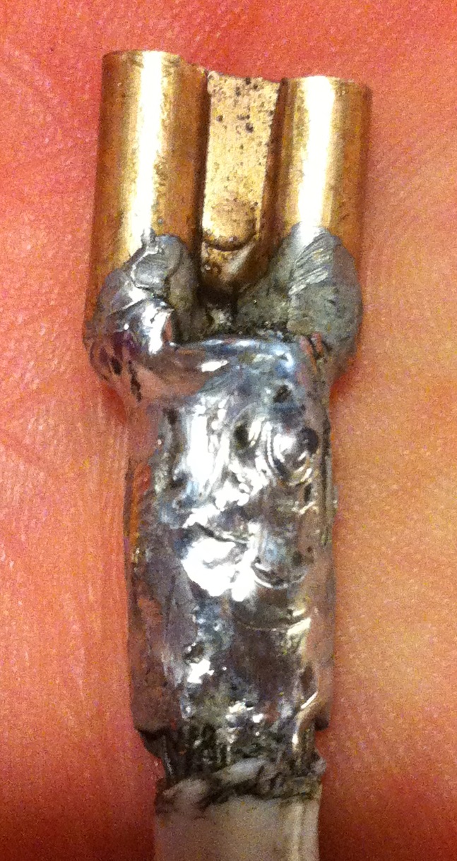
By the way, (this is a followup from a previous thread on contactors), I managed to solder some 4AWG wire onto the 3/8” faston female connectors so that I can connect my battery to the automotive cube relay and use it as a master relay as per the proposed diagram. Attached is a picture of the result…
it’s not the best example of workmanship, but it seems robust enough to me (though this may be difficult to judge from the picture). It will now be covered in shrink tubing for strain relief.
Looks like a great starting point . . . let's
continue to discuss its refinement.
Thank you… as usual your help is much appreciated.
Sacha
Bob . . .
| | - The Matronics AeroElectric-List Email Forum - | | | Use the List Feature Navigator to browse the many List utilities available such as the Email Subscriptions page, Archive Search & Download, 7-Day Browse, Chat, FAQ, Photoshare, and much more:
http://www.matronics.com/Navigator?AeroElectric-List |
|
| Description: |
|
| Filesize: |
23.73 KB |
| Viewed: |
6656 Time(s) |
|
| Description: |
|
| Filesize: |
342.28 KB |
| Viewed: |
6656 Time(s) |
|
|
|
| Back to top |
|
|
nuckolls.bob(at)aeroelect
Guest
|
| Posted: Mon Dec 02, 2013 6:51 am Post subject: kitfox /rotax 912 wiring diagram (variation on Z-16) |
|
|
At 03:32 PM 11/30/2013, you wrote:
| Quote: |
> To reduce electrical noise from the fuel pump, the capacitor
should be located at the fuel pump and connected to the positive
and negative wires of the fuel pump. I assume that is what you
have done in the winmail.dat file. Joe Gores
Yes it is. But I thought that the capacitor in parallel with the
fuel pump was to facilitate the starting of the pump not to reduce noise.
Sacha
|
Have there been any reported instances of noise from
a fuel pump?
Bob . . .
| | - The Matronics AeroElectric-List Email Forum - | | | Use the List Feature Navigator to browse the many List utilities available such as the Email Subscriptions page, Archive Search & Download, 7-Day Browse, Chat, FAQ, Photoshare, and much more:
http://www.matronics.com/Navigator?AeroElectric-List |
|
|
|
| Back to top |
|
|
nuckolls.bob(at)aeroelect
Guest
|
| Posted: Mon Dec 02, 2013 7:09 am Post subject: kitfox /rotax 912 wiring diagram (variation on Z-16) |
|
|
At 09:30 PM 11/29/2013, you wrote:
| Quote: |
OK, you have the dynamo working now. I see no other major
mistakes. I would not have all of those buttons on the control
stick because I know that I would get them mixed up and push the
wrong one. But that is a matter of personal preference. In the
lower right hand corner of the drawing is a 22,000 microfarad
capacitor that is connected between ground and the contactors. I do
not think that capacitor is needed. It does not hurt anything, but
is one more thing that could fail.
|
The large electrolytic capacitors common to
most PM/Rectifier-Regulator installations
is problematic. We know that these capacitors
have little benefit for smoothing ripple
voltage on the rectified output of the rectifier/
regulator.
There's no demonstrated benefit for reduction
of observable noise in headsets/radios.
The presence of this capacitor MIGHT be of
benefit when operating the system alternator-only
but I've not accomplished any testing to explore
or demonstrate this feature.
In any case, they've been installed on most if
not all PM alternator systems and certainly
don't hurt anything. But their benefits are
not yet qualified.
Bob . . .
| | - The Matronics AeroElectric-List Email Forum - | | | Use the List Feature Navigator to browse the many List utilities available such as the Email Subscriptions page, Archive Search & Download, 7-Day Browse, Chat, FAQ, Photoshare, and much more:
http://www.matronics.com/Navigator?AeroElectric-List |
|
|
|
| Back to top |
|
|
user9253
Joined: 28 Mar 2008
Posts: 1973
Location: Riley TWP Michigan
|
| Posted: Tue Dec 03, 2013 7:22 am Post subject: Re: kitfox /rotax 912 wiring diagram (variation on Z-16) |
|
|
| Quote: | Have there been any reported instances of noise from
a fuel pump? Bob . . . |
The Van's RV-12 kits comes with a capacitor and instructions for installing at the electric fuel pump. See note in the middle of this page:
http://www.vansaircraft.com/pdf/revisions/RV-12/31-05.pdf
I have not heard reports of audio noise from fuel pumps, but installed the capacitor per instructions for my RV-12.
Joe
| | - The Matronics AeroElectric-List Email Forum - | | | Use the List Feature Navigator to browse the many List utilities available such as the Email Subscriptions page, Archive Search & Download, 7-Day Browse, Chat, FAQ, Photoshare, and much more:
http://www.matronics.com/Navigator?AeroElectric-List |
|
_________________
Joe Gores |
|
| Back to top |
|
|
user9253
Joined: 28 Mar 2008
Posts: 1973
Location: Riley TWP Michigan
|
| Posted: Tue Dec 03, 2013 7:36 am Post subject: Re: kitfox /rotax 912 wiring diagram (variation on Z-16) |
|
|
| Quote: | In any case, they've been installed on most if
not all PM alternator systems and certainly
don't hurt anything. But their benefits are
not yet qualified. Bob . . . |
Sacha's schematic has two of those 22,000 microfarad capacitors, one on each side of the alternator relay. I questioned the need for two of them.
Bob, when you said the large electrolytic capacitor is problematic, did you mean that they are prone to fail?
Thanks, Joe
| | - The Matronics AeroElectric-List Email Forum - | | | Use the List Feature Navigator to browse the many List utilities available such as the Email Subscriptions page, Archive Search & Download, 7-Day Browse, Chat, FAQ, Photoshare, and much more:
http://www.matronics.com/Navigator?AeroElectric-List |
|
_________________
Joe Gores |
|
| Back to top |
|
|
uuccio(at)gmail.com
Guest
|
| Posted: Tue Dec 03, 2013 10:12 am Post subject: kitfox /rotax 912 wiring diagram (variation on Z-16) |
|
|
On Dec 2, 2013, at 16:08, "Robert L. Nuckolls, III" <nuckolls.bob(at)aeroelectric.com> wrote:
| Quote: | The presence of this capacitor MIGHT be of
benefit when operating the system alternator-only
but I've not accomplished any testing to explore
or demonstrate this feature.
|
This is what the Rotax installation manual says, that the capacitor protects the regulator in case the battery is taken offline.
| | - The Matronics AeroElectric-List Email Forum - | | | Use the List Feature Navigator to browse the many List utilities available such as the Email Subscriptions page, Archive Search & Download, 7-Day Browse, Chat, FAQ, Photoshare, and much more:
http://www.matronics.com/Navigator?AeroElectric-List |
|
|
|
| Back to top |
|
|
nuckollsr
Joined: 24 Mar 2009
Posts: 95
Location: Medicine Lodge, KS
|
| Posted: Wed Dec 04, 2013 7:00 am Post subject: Re: kitfox /rotax 912 wiring diagram (variation on Z-16) |
|
|
| Quote: | | Sacha's schematic has two of those 22,000 microfarad capacitors, one on each side of the alternator relay. I questioned the need for two of them. |
Good eye. I should have seen that too. Yeah, if any capacitor is needed, one is probably enough!
| Quote: |
Bob, when you said the large electrolytic capacitor is problematic, did you mean that they are prone to fail? |
No, I intended 'problematic' in that it's not clear that the capacitor is necessary or functions as the various assertions suggest. I have run bench tests on the B&C SD-8 alternator and found that adding the capacitor demonstrates no measurable benefit.
The schematic for the B&C PM regulator-rectifier is not materially different than the last one I saw for the Rotax-Ducatti R-R . . . the notion that adding a capacitor 'protects' the regulator if the battery becomes disconnected is not clear. I'm not suggesting that folks stop installing them . . . but given demonstrated inability/unwillingness of proponents for adding the capacitor to explain its function in demonstrable physics gives one pause to wonder.
I'd love to put one of the larger PM machines on the test bench with a Rotax-Ducatti R-R and explore details of its performance . . . but I've got a lot of more pressing goals right now.[/quote]
| | - The Matronics AeroElectric-List Email Forum - | | | Use the List Feature Navigator to browse the many List utilities available such as the Email Subscriptions page, Archive Search & Download, 7-Day Browse, Chat, FAQ, Photoshare, and much more:
http://www.matronics.com/Navigator?AeroElectric-List |
|
|
|
| Back to top |
|
|
|
|
You cannot post new topics in this forum
You cannot reply to topics in this forum
You cannot edit your posts in this forum
You cannot delete your posts in this forum
You cannot vote in polls in this forum
You cannot attach files in this forum
You can download files in this forum
|
Powered by phpBB © 2001, 2005 phpBB Group
|

