 |
Matronics Email Lists
Web Forum Interface to the Matronics Email Lists
|
| View previous topic :: View next topic |
| Author |
Message |
kenryan
Joined: 20 Oct 2009
Posts: 429
|
 Posted: Mon Dec 15, 2014 12:46 pm Post subject: voltage drop across relay Posted: Mon Dec 15, 2014 12:46 pm Post subject: voltage drop across relay |
 |
|
I have scanned chapter 11 but was not able to find the answer to this question: What would be the typical voltage drop across a relay in a 12 volt system using 10 gauge wire to carry about 20 amps?

  [quote][b]
| | - The Matronics AeroElectric-List Email Forum - | | | Use the List Feature Navigator to browse the many List utilities available such as the Email Subscriptions page, Archive Search & Download, 7-Day Browse, Chat, FAQ, Photoshare, and much more:
http://www.matronics.com/Navigator?AeroElectric-List |
|
|
|
| Back to top |
|
 |
ceengland7(at)gmail.com
Guest
|
| Posted: Mon Dec 15, 2014 1:12 pm Post subject: voltage drop across relay |
|
|
Should be in the range of a few millivolts, at most, if the contacts are in good shape. Wire size isn't relevant to voltage drop across the relay contacts.
Sent from my iPhone
On Dec 15, 2014, at 2:44 PM, Ken Ryan <keninalaska(at)gmail.com (keninalaska(at)gmail.com)> wrote:
[quote]I have scanned chapter 11 but was not able to find the answer to this question: What would be the typical voltage drop across a relay in a 12 volt system using 10 gauge wire to carry about 20 amps?
[b]
| | - The Matronics AeroElectric-List Email Forum - | | | Use the List Feature Navigator to browse the many List utilities available such as the Email Subscriptions page, Archive Search & Download, 7-Day Browse, Chat, FAQ, Photoshare, and much more:
http://www.matronics.com/Navigator?AeroElectric-List |
|
|
|
| Back to top |
|
|
nuckolls.bob(at)aeroelect
Guest
|
| Posted: Mon Dec 15, 2014 3:09 pm Post subject: voltage drop across relay |
|
|
At 14:44 2014-12-15, you wrote:
| Quote: | I have scanned chapter 11 but was not able to find the answer to this question: What would be the typical voltage drop across a relay in a 12 volt system using 10 gauge wire to carry about 20 amps?
|
Charlie's right . . . but I'm curious as
to what prompted the question.
In the best of all worlds, two pieces of
metal brought together to carry current
(switch and relay contacts) would produce
a zero-ohms joint but alas, we don't live
in a perfect world.
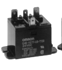
A relay in the same 'class' as you describe
[img]cid:7.1.0.9.0.20141215165823.01fc4710(at)aeroelectric.com.0[/img] [img]cid:7.1.0.9.0.20141215165823.01fc4710(at)aeroelectric.com.1[/img]
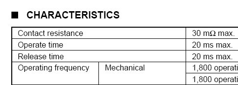
. . . has a published maximum resistance of 0.030 ohms
[img]cid:7.1.0.9.0.20141215165823.01fc4710(at)aeroelectric.com.2[/img]
according to specs . . . a drop of 20A x 0.030 ohms = 600 millivolts
or about 1.2 watts of dissipation at the contacts. I can
guarantee that contacts of that mass dumping that much
heat would not be long for this earth.
As a practical matter, any time you measure more than
100 millivolts across any set of switch or small relay
contacts at these kinds of loads, it's worth your time
to see if the critter is getting into trouble.
Bob . . .
| | - The Matronics AeroElectric-List Email Forum - | | | Use the List Feature Navigator to browse the many List utilities available such as the Email Subscriptions page, Archive Search & Download, 7-Day Browse, Chat, FAQ, Photoshare, and much more:
http://www.matronics.com/Navigator?AeroElectric-List |
|
| Description: |
|
| Filesize: |
631 Bytes |
| Viewed: |
16863 Time(s) |

|
| Description: |
|
| Filesize: |
18.55 KB |
| Viewed: |
16863 Time(s) |
|
| Description: |
|
| Filesize: |
42.9 KB |
| Viewed: |
16863 Time(s) |
|
|
|
| Back to top |
|
|
kenryan
Joined: 20 Oct 2009
Posts: 429
|
| Posted: Mon Dec 15, 2014 3:32 pm Post subject: voltage drop across relay |
|
|
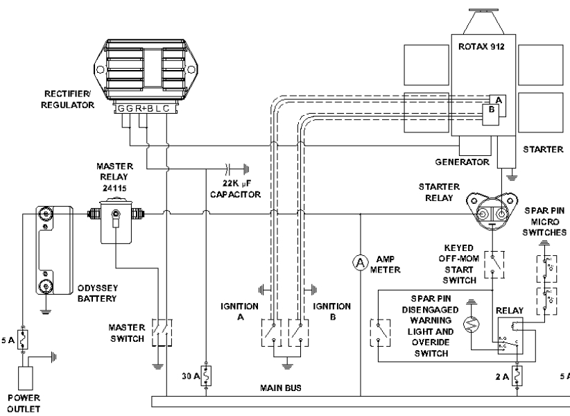
The answer to "what prompted the question" as to typical voltage drop across a 12 volt relay is:Â
The Rotax schematic has the regulator C wire (which measures voltage) going through a couple of relays on its way back to the battery. The text says that there should be no more than 0.2 volt difference between the battery and the C terminal. I was trying to get a handle on how much drop to expect from the two relays.
On Mon, Dec 15, 2014 at 2:08 PM, Robert L. Nuckolls, III <nuckolls.bob(at)aeroelectric.com (nuckolls.bob(at)aeroelectric.com)> wrote: | Quote: | At 14:44 2014-12-15, you wrote:
| Quote: | I have scanned chapter 11 but was not able to find the answer to this question: What would be the typical voltage drop across a relay in a 12 volt system using 10 gauge wire to carry about 20 amps?
|
  Charlie's right . . . but I'm curious as
  to what prompted the question.
  In the best of all worlds, two pieces of
  metal brought together to carry current
  (switch and relay contacts) would produce
  a zero-ohms joint but alas, we don't live
  in a perfect world.
  A relay in the same 'class' as you describe
Â
[img]cid:7.1.0.9.0.20141215165823.01fc4710(at)aeroelectric.com.0[/img] [img]cid:7.1.0.9.0.20141215165823.01fc4710(at)aeroelectric.com.1[/img]
 . . . has a published maximum resistance of 0.030 ohms
[img]cid:7.1.0.9.0.20141215165823.01fc4710(at)aeroelectric.com.2[/img]
 according to specs . . . a drop of 20A x 0.030 ohms = 600 millivolts
 or about 1.2 watts of dissipation at the contacts. I can
 guarantee that contacts of that mass dumping that much
 heat would not be long for this earth.
 As a practical matter, any time you measure more than
 100 millivolts across any set of switch or small relay
 contacts at these kinds of loads, it's worth your time
 to see if the critter is getting into trouble.
 Bob . . .
|
| | - The Matronics AeroElectric-List Email Forum - | | | Use the List Feature Navigator to browse the many List utilities available such as the Email Subscriptions page, Archive Search & Download, 7-Day Browse, Chat, FAQ, Photoshare, and much more:
http://www.matronics.com/Navigator?AeroElectric-List |
|
| Description: |
|
| Filesize: |
42.9 KB |
| Viewed: |
16863 Time(s) |

|
| Description: |
|
| Filesize: |
18.55 KB |
| Viewed: |
16863 Time(s) |

|
| Description: |
|
| Filesize: |
631 Bytes |
| Viewed: |
16863 Time(s) |

|
|
|
| Back to top |
|
|
nuckolls.bob(at)aeroelect
Guest
|
| Posted: Mon Dec 15, 2014 5:03 pm Post subject: voltage drop across relay |
|
|
At 17:30 2014-12-15, you wrote:
| Quote: | The answer to "what prompted the question" as to
typical voltage drop across a 12 volt relay is:Â
The Rotax schematic has the regulator C wire
(which measures voltage) going through a couple
of relays on its way back to the battery. The
text says that there should be no more than 0.2
volt difference between the battery and the C
terminal. I was trying to get a handle on how
much drop to expect from the two relays.
|
Oh . . . yeah . . .
Suggest you consider an architecture like
Z-16 that places no switches or relay
contacts in series with the regulator's
output (B&R) or sense lead (C) and
the bus.
Bob . . .
| | - The Matronics AeroElectric-List Email Forum - | | | Use the List Feature Navigator to browse the many List utilities available such as the Email Subscriptions page, Archive Search & Download, 7-Day Browse, Chat, FAQ, Photoshare, and much more:
http://www.matronics.com/Navigator?AeroElectric-List |
|
|
|
| Back to top |
|
|
nuckolls.bob(at)aeroelect
Guest
|
| Posted: Mon Dec 15, 2014 5:07 pm Post subject: voltage drop across relay |
|
|
At 17:30 2014-12-15, you wrote:
| Quote: | The answer to "what prompted the question" as to typical voltage drop across a 12 volt relay is:Â
The Rotax schematic has the regulator C wire (which measures voltage) going through a couple of relays on its way back to the battery. The text says that there should be no more than 0.2 volt difference between the battery and the C terminal. I was trying to get a handle on how much drop to expect from the two relays. |
I'm surprised they did that. Here's an excerpt from
another Rotax document that seems to avoid that
pitfall nicely . . .
[img]cid:7.1.0.9.0.20141215190447.01fd1770(at)aeroelectric.com.3[/img]
Bob . . .
| | - The Matronics AeroElectric-List Email Forum - | | | Use the List Feature Navigator to browse the many List utilities available such as the Email Subscriptions page, Archive Search & Download, 7-Day Browse, Chat, FAQ, Photoshare, and much more:
http://www.matronics.com/Navigator?AeroElectric-List |
|
| Description: |
|
| Filesize: |
157.69 KB |
| Viewed: |
16862 Time(s) |
|
|
|
| Back to top |
|
|
user9253
Joined: 28 Mar 2008
Posts: 1969
Location: Riley TWP Michigan
|
| Posted: Tue Dec 16, 2014 8:56 am Post subject: Re: voltage drop across relay |
|
|
The Rotax Installation Manual http://www.flyrotax.com/portaldata/5/dokus/d04967.pdf
shows a battery contactor between the battery and main bus and a 25 amp circuit breaker between the main bus and the regulator. There are no small relays used in the regulator circuit. During normal flight, only battery charging current flows through the battery contactor. Any voltage drop across the battery contactor does not affect the output of the voltage regulator. The Rotax wiring diagram has a couple of issues: the master switch does NOT shut off the dynamo, and the starter contactor is connected directly to the battery instead of being in series with the master contactor like many E-AB aircraft are wired.
The schematic that Bob posted is not from Rotax but is actually from Van's Aircraft RV-12. I recommend NOT using the Rotax schematic. Instead, wire the rectifier/regulator per Van's schematic with the addition of a 5 amp fuse in the terminal "C" circuit at the main bus. The regulator "C" sense circuit and "R+B" output circuit should be wired with separate paths to the main bus. Then the voltage drop to the "C" terminal will be minimized because only milliamps will flow in its circuit. Less current results in less voltage drop. Bob, please correct me if anything that I said is wrong.
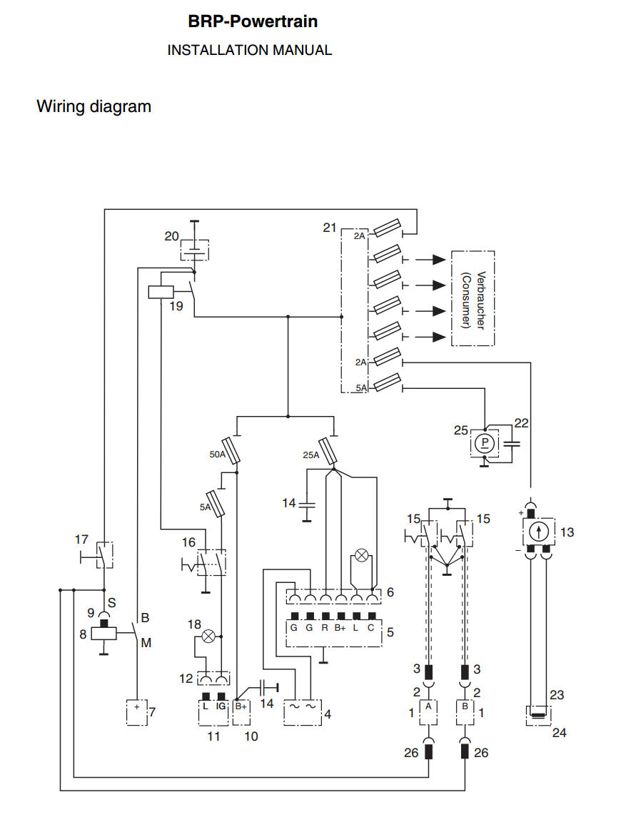
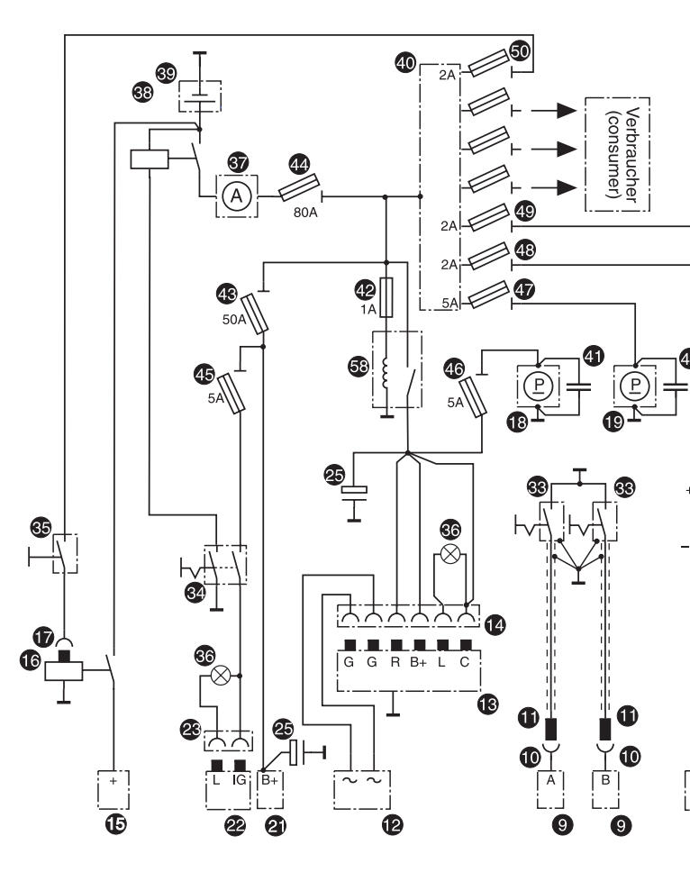
See attached picture of the Rotax wiring diagram.
Below is the key to reference numbers on the Rotax wiring diagram:
1. Electronic modules (A and B)
2-3. plug connection for ignition switch
4. Integrated generator
5-6. External regulator - rectifier with plug connections
7. Electric starter
8-9. Starter relay with plug connection
10-12. External alternator with connections
13. Electric rev-counter
14. Capacitor 22,000 microfarad
15. Ignition switches
16. Master switch
17. Starter switch
18. Control lamp
19. Battery relay (contactor)
20. Battery
21. Bus bar
22. Capacitor
23. Plug connection for trigger coil assy.
24. Trigger coil assy. (tachometer)
25. Electrical fuel pump
26. Starting equipment at the electronic modules
| | - The Matronics AeroElectric-List Email Forum - | | | Use the List Feature Navigator to browse the many List utilities available such as the Email Subscriptions page, Archive Search & Download, 7-Day Browse, Chat, FAQ, Photoshare, and much more:
http://www.matronics.com/Navigator?AeroElectric-List |
|
| Description: |
|
| Filesize: |
93.43 KB |
| Viewed: |
16837 Time(s) |
|
_________________
Joe Gores |
|
| Back to top |
|
|
kenryan
Joined: 20 Oct 2009
Posts: 429
|
| Posted: Tue Dec 16, 2014 9:18 am Post subject: voltage drop across relay |
|
|
Joe, The Rotax diagram I'm looking at is for the 914 and it has the C wire going through one relay plus the battery contactor. [Reference Link]


On Tue, Dec 16, 2014 at 7:56 AM, user9253 <fransew(at)gmail.com (fransew(at)gmail.com)> wrote:[quote]--> AeroElectric-List message posted by: "user9253" <fransew(at)gmail.com (fransew(at)gmail.com)>


 The Rotax Installation Manual http://www.flyrotax.com/portaldata/5/dokus/d04967.pdf

 shows a battery contactor between the battery and main bus and a 25 amp circuit breaker between the main bus and the regulator.  There are no small relays used in the regulator circuit.  During normal flight, only battery charging current flows through the battery contactor.  Any voltage drop across the battery contactor does not affect the output of the voltage regulator.  The Rotax wiring diagram has a couple of issues: the master switch does NOT shut off the dynamo, and the starter contactor is connected directly to the battery instead of being in series with the master contactor like many E-AB aircraft are wired.

   The schematic that Bob posted is not from Rotax but is actually from Van's Aircraft RV-12.  I recommend NOT using the Rotax schematic.  Instead, wire the rectifier/regulator per Van's schematic with the addition of a 5 amp fuse in the terminal "C" circuit at the main bus.  The regulator "C" sense circuit and "R+B" output circuit should be wired with separate paths to the main bus.  Then the voltage drop to the "C" terminal will be minimized because only milliamps will flow in its circuit.  Less current results in less voltage drop.  Bob, please correct me if anything that I said is wrong.


 See attached  picture of the Rotax wiring diagram.

 Below is the key to reference numbers on the Rotax wiring diagram:

 1.  Electronic modules (A and B)

 2-3. plug connection for ignition switch

 4. Integrated generator

 5-6.  External regulator - rectifier with plug connections

 7.  Electric starter

 8-9.  Starter relay with plug connection

 10-12.  External alternator with connections

 13.  Electric rev-counter

 14.  Capacitor 22,000 microfarad

 15.  Ignition switches

 16.  Master switch

 17.  Starter switch

 18.  Control lamp

 19.  Battery relay (contactor)

 20.  Battery

 21.  Bus bar

 22.  Capacitor

 23.  Plug connection for trigger coil assy.

 24.  Trigger coil assy. (tachometer)

 25.  Electrical fuel pump

 26.  Starting equipment at the electronic modules


 --------

 Joe Gores


 Read this topic online here:


 http://forums.matronics.com/viewtopic.php?p=435773#435773


 Attachments:


 http://forums.matronics.com//files/rotax_wiring_diagram_102.jpg


 ===========

 br> fts!)

 r> > com" target="_blank">www.aeroelectric.com

 w.buildersbooks.com" target="_blank">www.buildersbooks.com

 p.com" target="_blank">www.homebuilthelp.com

 e.com" target="_blank">www.mypilotstore.com

 " target="_blank">www.mrrace.com

 target="_blank">http://www.matronics.com/contribution

           -Matt Dralle, List Admin.

 ===========

  -

 Electric-List" target="_blank">http://www.matronics.com/Navigator?AeroElectric-List

 ===========

  FORUMS -

 _blank">http://forums.matronics.com

 ===========


 [b]
| | - The Matronics AeroElectric-List Email Forum - | | | Use the List Feature Navigator to browse the many List utilities available such as the Email Subscriptions page, Archive Search & Download, 7-Day Browse, Chat, FAQ, Photoshare, and much more:
http://www.matronics.com/Navigator?AeroElectric-List |
|
|
|
| Back to top |
|
|
user9253
Joined: 28 Mar 2008
Posts: 1969
Location: Riley TWP Michigan
|
| Posted: Tue Dec 16, 2014 2:19 pm Post subject: Re: voltage drop across relay |
|
|
| Quote: | | Joe, The Rotax diagram I'm looking at is for the 914 and it has the C wire going through one relay plus the battery contactor. |
Ken,
You are right. I was looking at the Rotax 912 schematic, not the 914 which has fuel injection. I can understand why the regulator "C" terminal is connected directly to the "R+B" terminals. They want the dynamo to supply power to the fuel pump with no way for the pilot to shut off the regulator. Therefore, I take back what I wrote about connecting terminal "C" according to the RV-12 schematic (unless all scenarios have been considered). If you wire the regulator according to Rotax's schematic and are concerned about the voltage drop across the regulator relay, then consider a double pole relay with the the poles connected in parallel. http://tinyurl.com/DPST-Relay
| | - The Matronics AeroElectric-List Email Forum - | | | Use the List Feature Navigator to browse the many List utilities available such as the Email Subscriptions page, Archive Search & Download, 7-Day Browse, Chat, FAQ, Photoshare, and much more:
http://www.matronics.com/Navigator?AeroElectric-List |
|
| Description: |
|
| Filesize: |
91.48 KB |
| Viewed: |
16823 Time(s) |
|
_________________
Joe Gores |
|
| Back to top |
|
|
kenryan
Joined: 20 Oct 2009
Posts: 429
|
| Posted: Tue Dec 16, 2014 2:35 pm Post subject: voltage drop across relay |
|
|
Joe, thanks for the DPST relay tip. The Rotax 914 isn't fuel injected (it's turbocharged) but like a fuel injected engine it must have the electrical fuel pump working in order to run.


On Tue, Dec 16, 2014 at 1:19 PM, user9253 <fransew(at)gmail.com (fransew(at)gmail.com)> wrote:[quote]--> AeroElectric-List message posted by: "user9253" <fransew(at)gmail.com (fransew(at)gmail.com)>


 > Joe, The Rotax diagram I'm looking at is for the 914 and it has the C wire going through one relay plus the battery contactor.


 Ken,

 You are right.  I was looking at the Rotax 912 schematic, not the 914 which has fuel injection.  I can understand why the regulator  "C" terminal is connected directly to the "R+B" terminals.  They want the dynamo to supply power to the fuel pump with no way for the pilot to shut off the regulator. Therefore, I take back what I wrote about connecting terminal "C" according to the RV-12 schematic (unless all scenarios have been considered).  If you wire the regulator according to Rotax's schematic and are concerned about the voltage drop across the regulator relay, then consider a double pole relay with the the poles connected in parallel. http://tinyurl.com/DPST-Relay


 --------

 Joe Gores


 Read this topic online here:


 http://forums.matronics.com/viewtopic.php?p=435785#435785


 ===========

 br> fts!)

 r> > com" target="_blank">www.aeroelectric.com

 w.buildersbooks.com" target="_blank">www.buildersbooks.com

 p.com" target="_blank">www.homebuilthelp.com

 e.com" target="_blank">www.mypilotstore.com

 " target="_blank">www.mrrace.com

 target="_blank">http://www.matronics.com/contribution

           -Matt Dralle, List Admin.

 ===========

  -

 Electric-List" target="_blank">http://www.matronics.com/Navigator?AeroElectric-List

 ===========

  FORUMS -

 _blank">http://forums.matronics.com

 ===========


 [b]
| | - The Matronics AeroElectric-List Email Forum - | | | Use the List Feature Navigator to browse the many List utilities available such as the Email Subscriptions page, Archive Search & Download, 7-Day Browse, Chat, FAQ, Photoshare, and much more:
http://www.matronics.com/Navigator?AeroElectric-List |
|
|
|
| Back to top |
|
|
|
|
You cannot post new topics in this forum
You cannot reply to topics in this forum
You cannot edit your posts in this forum
You cannot delete your posts in this forum
You cannot vote in polls in this forum
You cannot attach files in this forum
You can download files in this forum
|
Powered by phpBB © 2001, 2005 phpBB Group
|

