 |
Matronics Email Lists
Web Forum Interface to the Matronics Email Lists
|
| View previous topic :: View next topic |
| Author |
Message |
user9253
Joined: 28 Mar 2008
Posts: 1967
Location: Riley TWP Michigan
|
 Posted: Wed Jan 14, 2015 7:35 pm Post subject: Re: UN-FUSED MAIN BUS FEEDER Posted: Wed Jan 14, 2015 7:35 pm Post subject: Re: UN-FUSED MAIN BUS FEEDER |
 |
|
| Quote: | | What does Van's factory wiring dictate? |
All RV-12s, that are intended to be registered as E-LSA, MUST be built exactly according to plans using every part supplied by Van's Aircraft. No modifications or substitutions are allowed. Van's advertises that every part needed to build the plane is included in the kit except fluids. That is pretty much true with few exceptions. The wires are supplied already cut to length and terminated. It is plug and play, kind of like assembling a desk top computer. Some builders have wired their RV-12s in a few days, possibly one weekend. The kit does not come with any protection for the #12 AWG main power feeder. The good news is that after receiving the airworthiness certificate and competing the flight test phase, modifications to E-LSA aircraft ARE allowed. However, factory-built S-LSA aircraft can not be modified without written permission from the factory.
Joe
| | - The Matronics AeroElectric-List Email Forum - | | | Use the List Feature Navigator to browse the many List utilities available such as the Email Subscriptions page, Archive Search & Download, 7-Day Browse, Chat, FAQ, Photoshare, and much more:
http://www.matronics.com/Navigator?AeroElectric-List |
|
_________________
Joe Gores |
|
| Back to top |
|
 |
jluckey(at)pacbell.net
Guest
|
| Posted: Wed Jan 14, 2015 7:58 pm Post subject: UN-FUSED MAIN BUS FEEDER |
|
|
Bob,

I think there's been a slight mis-communication:


ok, here we go, follow me down into the weeds...


"The ASTM specs that the RV-12 is certificated under specifically >prohibit the use of of a circuit protector that is not resetable by the pilot."

That quote is someone's interpretation of the ASTM Standard - NOT an actual quote from the Standard.

I was looking for wording in the ASTM document that supported that claim and after reading the  excerpt


you provided, I think we both concluded that the above statement is not supported by the words in the


Standard.

This is the kind of detail that  can be difficult to express in prose without getting wordy (and boring).  If we

were sitting at the same table, we'd have it cleared up in less than a minute.

-Jeff


     On Wednesday, January 14, 2015 6:13 PM, "Robert L. Nuckolls, III" <nuckolls.bob(at)aeroelectric.com> wrote:

   --> AeroElectric-List message posted by: "Robert L. Nuckolls, III" <nuckolls.bob(at)aeroelectric.com (nuckolls.bob(at)aeroelectric.com)>At 16:17 2015-01-14, you wrote:>Oops!  My paraphrasing was inaccurate.  Here is what the other poster said:>>"The ASTM specs  that the RV-12 is certificated under specifically >prohibit the use of of a circuit protector that is not resetable by the pilot.    Opps . . . yeah, that makes a difference. Can't imagine    why that assertion is part of the spec . . . there's    no foundation in FMEA for the outcome of any given    flight by fiddling with circuit protection in the air.>That means the wire highlighted in this discussion can not have a >fusible link or any other circuit protection that would actually be >capable of preventing a failure in the location that this one was."   My argument would be that the fusible link or ANL   at  the battery contactor is not unlike similar devices   scattered about the airplane on King Airs and   their hot-air cousins . . . and those cannot be reached   by pilots either. Lots of breakers on those airplanes   can't be reached either.  These are not systems fuses, they're   a hedge against catastrophic events that either (1) put   every device on that feeder at risk of going dark or (2) the   whole damned airplane at risk of going down very brightly.   I'd let the enforcer of requirements choose . . .>Bob, In reading the text you supplied, I did not see anything that >supports the above statement.  Is there more  to the ASTM doc that >supports the above?>>I'm simply trying to understand what the "Standards" ACTUALLY say. >Therefore I'm trying to filter-out hearsay, mis-interpretation, >urban legend, & wive's tales.   Understand . . . I think I expressed some misgivings   about the relative goodness of this new 'spec'.   Gee, only 33 pages long, a few years old . . . bet the   guys sitting around the table on this one never   did an FMEA or turned wrenches on airplanes.   Consider AC43-13 . . . DECADES old and sifted by   dozens of high-powered spec writers over the years.

 [quote][b]
| | - The Matronics AeroElectric-List Email Forum - | | | Use the List Feature Navigator to browse the many List utilities available such as the Email Subscriptions page, Archive Search & Download, 7-Day Browse, Chat, FAQ, Photoshare, and much more:
http://www.matronics.com/Navigator?AeroElectric-List |
|
|
|
| Back to top |
|
|
nuckolls.bob(at)aeroelect
Guest
|
| Posted: Thu Jan 15, 2015 8:14 am Post subject: UN-FUSED MAIN BUS FEEDER |
|
|
At 21:57 2015-01-14, you wrote:
| Quote: | Bob,
I think there's been a slight mis-communication:
ok, here we go, follow me down into the weeds...
"The ASTM specs that the RV-12 is certificated under specifically
>prohibit the use of of a circuit protector that is not resetable by the pilot."
That quote is someone's interpretation of the ASTM Standard - NOT an actual quote from the Standard.
I was looking for wording in the ASTM document that supported that claim and after reading the excerpt
you provided, I think we both concluded that the above statement is not supported by the words in the
Standard.
This is the kind of detail that can be difficult to express in prose without getting wordy (and boring). If we
were sitting at the same table, we'd have it cleared up in less than a minute. |
You got that right. Let's pour another cup of coffee
and sift through it . . .
A2.9.2 Circuit Protection Requirements Circuit overload
protection (fuses or circuit breakers) must: A2.9.2.1 Be installed on each circuit containing wiring, equipment, or other components rated for less than the maximum output of the battery and alternator or generator;
A2.9.2.2 Be appropriately rated for each component installed on the protected circuit;
A2.9.2.3 Be accessible to and in clear view of the pilot;
A2.9.2.4 Open before the conductor emits smoke; and
A2.9.2.5 Automatic re-set circuit breakers may not be used.
I think it's A2.9.2.3 from which an ASSUMPTION might
be made that the writers intend for all circuit protection
to be accessible to (and extrapolated to include re-setable)
the pilot.
The spirit and intent is not clear. One might think that
having a clear view is good as a tell . . . warning that
a circuit protector has opened. Except you can't 'see' blown
fuses. Further, a pilot is 100x more likely to detect
loss of system functionality first than to see a popped
breaker. We understand further that there are many more
ways a system can be rendered inop than a simple fault
on the power supply line. Hence, making the circuit protector
visible and/or reachable becomes a distraction and adds
no demonstrable value going to comfortable termination
of the flight.
Bob . . . [quote][b]
| | - The Matronics AeroElectric-List Email Forum - | | | Use the List Feature Navigator to browse the many List utilities available such as the Email Subscriptions page, Archive Search & Download, 7-Day Browse, Chat, FAQ, Photoshare, and much more:
http://www.matronics.com/Navigator?AeroElectric-List |
|
|
|
| Back to top |
|
|
ceengland7(at)gmail.com
Guest
|
| Posted: Thu Jan 15, 2015 10:42 am Post subject: UN-FUSED MAIN BUS FEEDER |
|
|
On 1/15/2015 10:13 AM, Robert L. Nuckolls, III wrote:
| Quote: | At 21:57 2015-01-14, you wrote:
| Quote: | Bob,
I think there's been a slight mis-communication:
ok, here we go, follow me down into the weeds...
"The ASTM specs that the RV-12 is certificated under specifically
>prohibit the use of of a circuit protector that is not resetable by the pilot."
That quote is someone's interpretation of the ASTM Standard - NOT an actual quote from the Standard.
I was looking for wording in the ASTM document that supported that claim and after reading the excerpt
you provided, I think we both concluded that the above statement is not supported by the words in the
Standard.
This is the kind of detail that can be difficult to express in prose without getting wordy (and boring). If we
were sitting at the same table, we'd have it cleared up in less than a minute. |
You got that right. Let's pour another cup of coffee
and sift through it . . .
A2.9.2 Circuit Protection Requirements Circuit overload
protection (fuses or circuit breakers) must: A2.9.2.1 Be installed on each circuit containing wiring, equipment, or other components rated for less than the maximum output of the battery and alternator or generator;
A2.9.2.2 Be appropriately rated for each component installed on the protected circuit;
A2.9.2.3 Be accessible to and in clear view of the pilot;
A2.9.2.4 Open before the conductor emits smoke; and
A2.9.2.5 Automatic re-set circuit breakers may not be used.
I think it's A2.9.2.3 from which an ASSUMPTION might
be made that the writers intend for all circuit protection
to be accessible to (and extrapolated to include re-setable)
the pilot.
The spirit and intent is not clear. One might think that
having a clear view is good as a tell . . . warning that
a circuit protector has opened. Except you can't 'see' blown
fuses. Further, a pilot is 100x more likely to detect
loss of system functionality first than to see a popped
breaker. We understand further that there are many more
ways a system can be rendered inop than a simple fault
on the power supply line. Hence, making the circuit protector
visible and/or reachable becomes a distraction and adds
no demonstrable value going to comfortable termination
of the flight.
Bob . . .
|
What's really nonsensical is A2.9.2.2, which is contrary to the real reason for the protection (the wire), and impossible to implement if there's more than one device on a circuit.
Charlie
[quote][b]
| | - The Matronics AeroElectric-List Email Forum - | | | Use the List Feature Navigator to browse the many List utilities available such as the Email Subscriptions page, Archive Search & Download, 7-Day Browse, Chat, FAQ, Photoshare, and much more:
http://www.matronics.com/Navigator?AeroElectric-List |
|
|
|
| Back to top |
|
|
user9253
Joined: 28 Mar 2008
Posts: 1967
Location: Riley TWP Michigan
|
| Posted: Thu May 07, 2015 7:26 am Post subject: Re: UN-FUSED MAIN BUS FEEDER |
|
|
Since there is already an ANL fuse installed to protect the alternator "B" lead, why not use that same fuse to protect the main power bus feeder?  See attached drawing.  One fuse can protect two circuits with no weight or cost penalty.  Of course if the alternator shorts out and blows the fuse, power is lost to the main bus.  That is unlikely to happen.  And if it does, the pilot can turn on the E-BUS switch (not shown on the drawing for simplicity).

Joe
| | - The Matronics AeroElectric-List Email Forum - | | | Use the List Feature Navigator to browse the many List utilities available such as the Email Subscriptions page, Archive Search & Download, 7-Day Browse, Chat, FAQ, Photoshare, and much more:
http://www.matronics.com/Navigator?AeroElectric-List |
|
| Description: |
|
| Filesize: |
47.65 KB |
| Viewed: |
5439 Time(s) |

|
_________________
Joe Gores |
|
| Back to top |
|
|
user9253
Joined: 28 Mar 2008
Posts: 1967
Location: Riley TWP Michigan
|
| Posted: Thu May 07, 2015 8:01 am Post subject: Re: UN-FUSED MAIN BUS FEEDER |
|
|
Obviously two circuits should not share the same fuse if there are loads on either circuit that are critical to flight safety, for instance retractable landing gear or landing lights or etc.
| | - The Matronics AeroElectric-List Email Forum - | | | Use the List Feature Navigator to browse the many List utilities available such as the Email Subscriptions page, Archive Search & Download, 7-Day Browse, Chat, FAQ, Photoshare, and much more:
http://www.matronics.com/Navigator?AeroElectric-List |
|
_________________
Joe Gores |
|
| Back to top |
|
|
jluckey(at)pacbell.net
Guest
|
| Posted: Thu May 07, 2015 8:06 am Post subject: UN-FUSED MAIN BUS FEEDER |
|
|
Joe,

You put your finger right on it - you don't want trouble with the alternator wire to kill the whole system.


As we all know, the likelihood of failure events is difficult to quantify. Something to consider is that the big wire that goes out to the alternator is in a pretty hostile environment.  Lots of heat, vibration, sharp edges, (clumsy mechanics), etc.

The additional cost to add a second current limiter is so small.

BTW - When the occasion presents itself, I have been asking friends & colleagues to send me wiring diagrams of airplanes they are flying or training in, and have found, in that small sample, all aircraft use current limiters in the primary feed line.


-Jeff


     On Thursday, May 7, 2015 8:43 AM, user9253 <fransew(at)gmail.com> wrote:


 --> AeroElectric-List message posted by: "user9253" <fransew(at)gmail.com (fransew(at)gmail.com)>


Since there is already an ANL fuse installed to protect the alternator "B" lead, why not use that same fuse to protect the main power bus feeder?  See attached drawing.  One fuse can protect two circuits with no weight or cost penalty.  Of course if the alternator shorts out and blows the fuse, power is lost to the main bus.  That is unlikely to happen.  And if it does, the pilot can turn on the E-BUS switch (not shown on the drawing for simplicity).

Joe


--------

Joe Gores


Read this topic online here:


http://forums.matronics.com/viewtopic.php?p=441831#441831


Attachments:


http://forums.matronics.com//files/main_anl_=          - The AeroElectric-List Email Forum -avigator?AeroElectric-List" target="_blank">http://www.matronics.com/Navi========================
| | - The Matronics AeroElectric-List Email Forum - | | | Use the List Feature Navigator to browse the many List utilities available such as the Email Subscriptions page, Archive Search & Download, 7-Day Browse, Chat, FAQ, Photoshare, and much more:
http://www.matronics.com/Navigator?AeroElectric-List |
|
|
|
| Back to top |
|
|
nuckolls.bob(at)aeroelect
Guest
|
| Posted: Thu May 07, 2015 8:10 am Post subject: UN-FUSED MAIN BUS FEEDER |
|
|
At 10:26 2015-05-07, you wrote:
--> AeroElectric-List message posted by: "user9253" <fransew(at)gmail.com>
Since there is already an ANL fuse installed to protect the alternator "B" lead, why not use that same fuse to protect the main power bus feeder? See attached drawing. One fuse can protect two circuits with no weight or cost penalty. Of course if the alternator shorts out and blows the fuse, power is lost to the main bus. That is unlikely to happen. And if it does, the pilot can turn on the E-BUS switch (not shown on the drawing for simplicity).
Circuit protection has TWO functions:
(1) Protect associated wiring and
(2) prevent a failure from propagating
across multiple systems. The B-lead
protection assumes that probability
of a short in alternator diodes,
while small, is not zero. Hence,
b-lead protection. If that device
WERE called upon to do it's job, it
would disconnect both the alternator
and main bus feeder . . . a condition
contrary to design goals.
A century of lessons learned suggest
that "protection" for properly installed
bus feeders is unnecessary. I've seen
"main breakers" installed in these feeders
on numerous OBAM aircraft schematics over
the years. Invariably, they are installed
on the panel at the junction of the main
bus and the feed line. IF there were any
serious threat to a bus feeder, protection
would have to be installed at the OTHER
end. But you will find no such protection
on any TC aircraft I'm aware of.
It's a function of FMEA and probabilities.
Got into a similar discussion with a gray-
beard yesterday. He was an employee of one
of my customers. I was talking about the
practice of paralleling multiple pins
in a connector for the purpose of boosting
current carrying capacity . . . with the
caveat that each of the paralleled pins
needed a 'ballasting resistor' in the
form of a 12" length of wire.
He offered up the standard argument, "But
you cannot detect a latent failure of
one pin."
"True. But you just did a failure analysis
on this system. After all the magic numbers
were stirred into the reliability stew, you
came up with a one-failure-in-10-to-the-minus-
amazing number."
"Yes," says he.
"Okay, here is a command signal pin right next
to my cluster of paralleled pins."
"Okay."
"A failure in that single pin has the ability
to take the system down."
"Yeah."
"But your probability stew says this single
pin offers so little risk for failure
that the 10-to-the-minus-amazing numbers
for the whole system are not challenged."
"Yeaahhh . . ."
"Okay, how is one pin paralleled with five
others any different?"
The conversation got real quiet there. They
went off to consider this further. Had this
same conversation with a Navy techno-wiennie
about 20 years ago. That conversation only
lasted about 10 minutes.
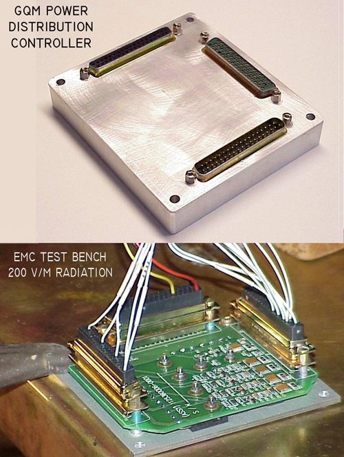
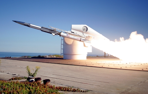
[img]cid:.0[/img]
The first flight of this vehicle featured a power
distribution box that routed 25 amp feeders through D-sub
connectors.
[img]cid:.1[/img]
It's all about properties of materials and management
of energy . . .
Bob . . .
| | - The Matronics AeroElectric-List Email Forum - | | | Use the List Feature Navigator to browse the many List utilities available such as the Email Subscriptions page, Archive Search & Download, 7-Day Browse, Chat, FAQ, Photoshare, and much more:
http://www.matronics.com/Navigator?AeroElectric-List |
|
| Description: |
|
| Filesize: |
280.48 KB |
| Viewed: |
5428 Time(s) |
|
| Description: |
|
| Filesize: |
105.49 KB |
| Viewed: |
5428 Time(s) |
|
|
|
| Back to top |
|
|
|
|
You cannot post new topics in this forum
You cannot reply to topics in this forum
You cannot edit your posts in this forum
You cannot delete your posts in this forum
You cannot vote in polls in this forum
You cannot attach files in this forum
You can download files in this forum
|
Powered by phpBB © 2001, 2005 phpBB Group
|

