 |
Matronics Email Lists
Web Forum Interface to the Matronics Email Lists
|
| View previous topic :: View next topic |
| Author |
Message |
Jump4way
Joined: 18 May 2015
Posts: 14
|
 Posted: Tue Jan 12, 2016 6:03 pm Post subject: Electrical system design critique Posted: Tue Jan 12, 2016 6:03 pm Post subject: Electrical system design critique |
 |
|
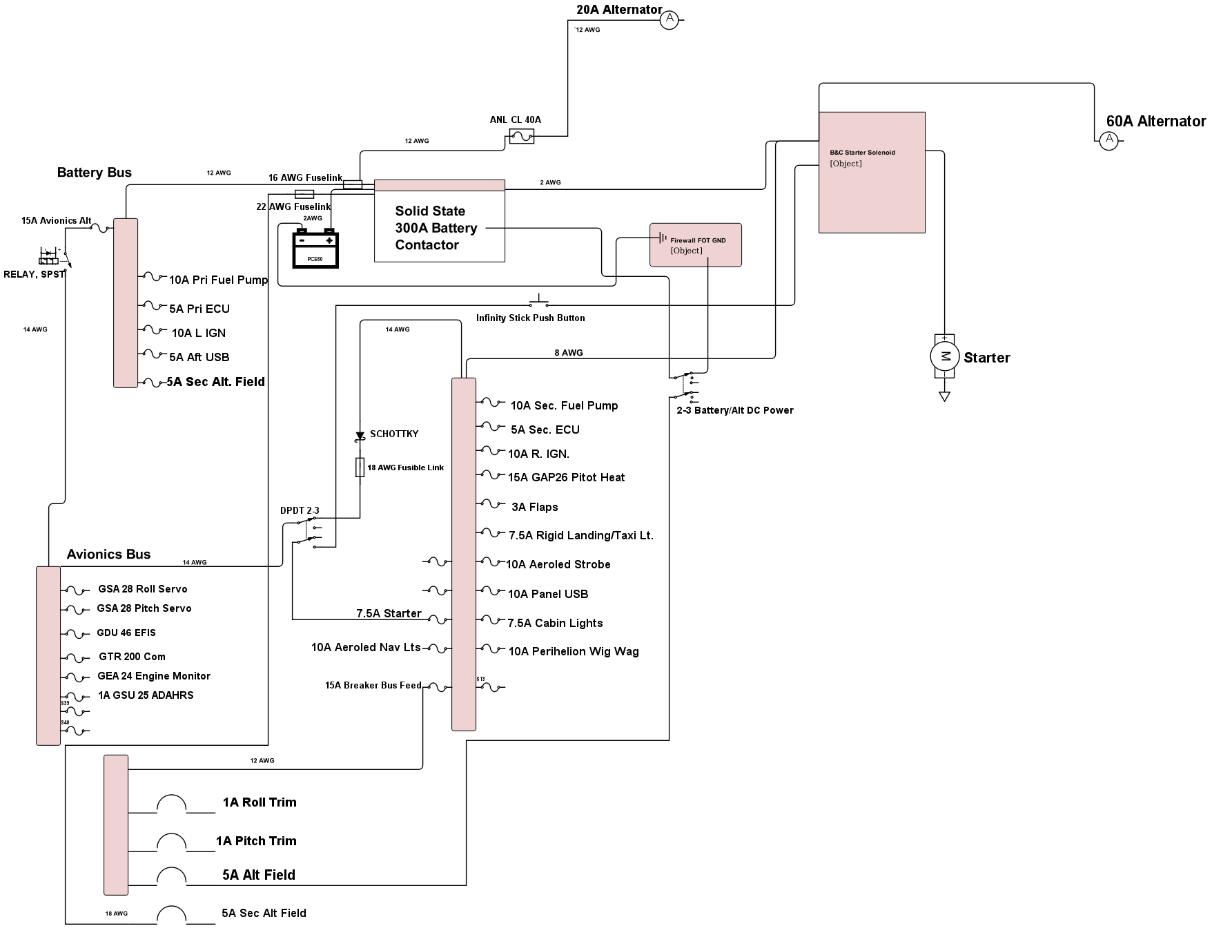
I'm working on my electrical system design. My plan is to install the EFII system using two alternators and one battery. The primary ECU, injector, fuel pump, and ignition will be powered off the always hot battery bus with the secondary set of the above powered off of the main bus.


I've chosen to install a couple of fusible links in areas where the aeroelectric connection book recommends wire runs 6" or less and I was unable to achieve that. I'm not sure if a run of 2-3 ft would require a fusible link... still scratching my head on that. I haven't completed the diagram quite yet as I haven't decided on which alternator/regulator combo to go with so that portion is left mostly out at this point.


Avionics haven't been purchased yet but I'm leaning towards the Garmin G3x suite of instruments.


Any feedback would be very appreciated. I apologize for the quality of the drawing.
| | - The Matronics AeroElectric-List Email Forum - | | | Use the List Feature Navigator to browse the many List utilities available such as the Email Subscriptions page, Archive Search & Download, 7-Day Browse, Chat, FAQ, Photoshare, and much more:
http://www.matronics.com/Navigator?AeroElectric-List |
|
| Description: |
|
| Filesize: |
132.75 KB |
| Viewed: |
24685 Time(s) |
|
|
|
| Back to top |
|
 |
user9253
Joined: 28 Mar 2008
Posts: 1972
Location: Riley TWP Michigan
|
| Posted: Tue Jan 12, 2016 8:23 pm Post subject: Re: Electrical system design critique |
|
|
Does the solid state battery contactor conduct in BOTH directions?

Is it rated for starter current?

The 60 amp alternator needs a fuse located close to the contactors.

If the 5 amp alternator field wire shorts out, the 15 amp fuse will likely blow before the circuit breaker trips.  I recommend not putting two circuit protection devices in series.

A separate avionics bus is not necessary and introduces unnecessary failure points.  Read this thread:

http://forums.matronics.com/viewtopic.php?t=16757246&sid=74d855944e77ced507a5bb87d7f9a72f

and this document:

http://www.aeroelectric.com/articles/avmaster.pdf
| | - The Matronics AeroElectric-List Email Forum - | | | Use the List Feature Navigator to browse the many List utilities available such as the Email Subscriptions page, Archive Search & Download, 7-Day Browse, Chat, FAQ, Photoshare, and much more:
http://www.matronics.com/Navigator?AeroElectric-List |
|
_________________
Joe Gores |
|
| Back to top |
|
|
Jump4way
Joined: 18 May 2015
Posts: 14
|
| Posted: Wed Jan 13, 2016 5:20 am Post subject: Re: Electrical system design critique |
|
|
The solid state disconnect is rated at 300 amps with 500 amps for one second. It's not clear to me whether it is rated the same in both directions. Here is a link to the documentation they provide. http://www.waytekwire.com/datasheet/44407.pdf


Good catch on the ANL fuse. I'll put that in.


For the breaker bus feed, would you just leave that 12 gauge wire unprotected from the main bus?


Any comments on the location and usage of the fuse links?


Also, I'm conflicted about the placement of the primary and secondary engine related items. Any recommendation on which bus to locate the primary ECU, ignition, and fuel pump?


Thanks for your time and critique.
| | - The Matronics AeroElectric-List Email Forum - | | | Use the List Feature Navigator to browse the many List utilities available such as the Email Subscriptions page, Archive Search & Download, 7-Day Browse, Chat, FAQ, Photoshare, and much more:
http://www.matronics.com/Navigator?AeroElectric-List |
|
|
|
| Back to top |
|
|
jmjones2000(at)mindspring
Guest
|
| Posted: Wed Jan 13, 2016 6:16 am Post subject: Electrical system design critique |
|
|
I can confirm that the solid state contractor does in fact conduct both directions. I'm running this setup already and it works great.
I have an ANL fuse installed by the contractor in the main alternator B lead. I can send pictures if interested. I also have a fuse in the aux alternator b lead.
Andy,
If you wish, I can send you my final diagram on how I wired this exact same setup. I'm very happy with it. I have pictures also.
Justin
| Quote: | On Jan 13, 2016, at 08:20, Jump4way <andydelk(at)gmail.com> wrote:
The solid state disconnect is rated at 300 amps with 500 amps for one second. It's not clear to me whether it is rated the same in both directions. Here is a link to the documentation they provide. http://www.waytekwire.com/datasheet/44407.pdf
Good catch on the ANL fuse. I'll put that in.
For the breaker bus feed, would you just leave that 12 gauge wire unprotected from the main bus?
Any comments on the location and usage of the fuse links?
Also, I'm conflicted about the placement of the primary and secondary engine related items. Any recommendation on which bus to locate the primary ECU, ignition, and fuel pump?
Thanks for your time and critique.
Read this topic online here:
http://forums.matronics.com/viewtopic.php?p=451945#451945
|
| | - The Matronics AeroElectric-List Email Forum - | | | Use the List Feature Navigator to browse the many List utilities available such as the Email Subscriptions page, Archive Search & Download, 7-Day Browse, Chat, FAQ, Photoshare, and much more:
http://www.matronics.com/Navigator?AeroElectric-List |
|
|
|
| Back to top |
|
|
user9253
Joined: 28 Mar 2008
Posts: 1972
Location: Riley TWP Michigan
|
| Posted: Wed Jan 13, 2016 8:59 am Post subject: Re: Electrical system design critique |
|
|
| Quote: | | For the breaker bus feed, would you just leave that 12 gauge wire unprotected from the main bus? |
The short answer is yes. Ideally every wire should be protected against over current and short circuits. But the consequences of opening a circuit must be considered. In this circuit, over current is not an issue because the circuit breakers protect against that. What about short circuit protection? It depends on the length of the #12 wire and danger of the circuit breaker bus shorting to ground. If good workmanship is used, wires are well supported, and bus is insulated, then I would leave that 15 amp fuse out.
But why even have that bus? Connect the alternator field breaker to the main power bus with a short wire. Move the pitch and roll trim circuits to the essential bus and protect them with fuses, not breakers. If a fuse blows, there is a reason. Wait until safely on the ground to troubleshoot.
Consider replacing the 15 amp avionics fuse with a fusible link.
The DPDT switch, used in series with the diode and used for starter interlock, is unnecessary. If eliminated, it can not break.
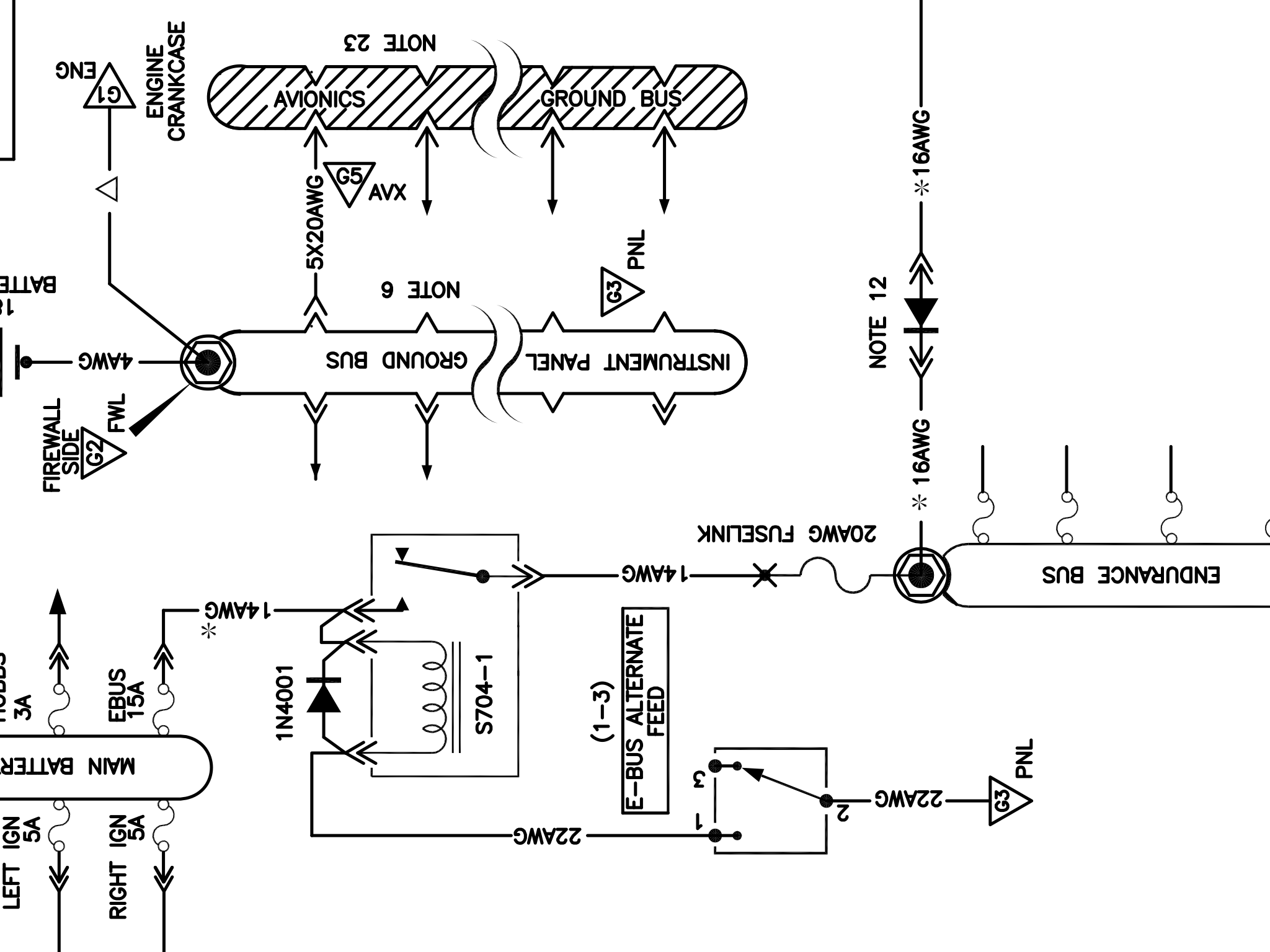
Notice on Bob's Z-13/8 that there is a fusible link connected to the top of the endurance bus. That fusible link protects the wire (if shorted) above it from current coming from the main power bus.
Maybe eliminate the fusible link supplying power to the battery bus. If properly installed and insulated, the battery bus will not short to ground. I would rather take a chance on that #12 wire burning open than have the engine quit because the fusible link failed.
| | - The Matronics AeroElectric-List Email Forum - | | | Use the List Feature Navigator to browse the many List utilities available such as the Email Subscriptions page, Archive Search & Download, 7-Day Browse, Chat, FAQ, Photoshare, and much more:
http://www.matronics.com/Navigator?AeroElectric-List |
|
_________________
Joe Gores |
|
| Back to top |
|
|
nuckolls.bob(at)aeroelect
Guest
|
| Posted: Wed Jan 13, 2016 10:51 am Post subject: Electrical system design critique |
|
|
| Quote: |
Good catch on the ANL fuse. I'll put that in.
For the breaker bus feed, would you just leave that 12 gauge wire unprotected from the main bus?
Any comments on the location and usage of the fuse links? |
Fusible links are SELDOM needed . . . 99%
of all your branch circuit protection should
be done with fuses/breakers.
| Quote: | | Also, I'm conflicted about the placement of the primary and secondary engine related items. Any recommendation on which bus to locate the primary ECU, ignition, and fuel pump? |
Draw up a power distribution diagram . . .
or copy one out of Appenedix Z and
start assigning system loads to the
various busses.
Verbal discussions of design philosophy
and technique is fraught with opportunity
for misunderstanding and error. A drawing
says it all . . . in ANY language.
Bob . . .
| | - The Matronics AeroElectric-List Email Forum - | | | Use the List Feature Navigator to browse the many List utilities available such as the Email Subscriptions page, Archive Search & Download, 7-Day Browse, Chat, FAQ, Photoshare, and much more:
http://www.matronics.com/Navigator?AeroElectric-List |
|
|
|
| Back to top |
|
|
Jump4way
Joined: 18 May 2015
Posts: 14
|
| Posted: Wed Jan 13, 2016 6:15 pm Post subject: Re: Electrical system design critique |
|
|
First off... thanks to everyone for taking to time to weed through my diagram and offering suggestions.
| Quote: | But why even have that bus? Connect the alternator field breaker to the main power bus with a short wire. Move the pitch and roll trim circuits to the essential bus and protect them with fuses, not breakers. If a fuse blows, there is a reason. Wait until safely on the ground to troubleshoot.
|
The idea of having the trim on circuit breakers was to have a means of disconnecting the pitch and roll trim in the rare instance of a runaway trim. I suppose a switch could be used for that regard but I thought circuit breakers would be a better way to kill two birds with one stone. I do not intend to have the need to use the circuit breakers as a switch on any type of regular basis.
| Quote: | | The DPDT switch, used in series with the diode and used for starter interlock, is unnecessary. If eliminated, it can not break. |
I was using this switch as a means to disable to avionics bus during engine start along with a means to disable to starter from the pushbutton on the infinity stick during flight in case it were to be inadvertantly pushed. The switch is rated at 15A which might in itself be a point of failure at some point as you suggest with your link regarding avionics busses.
| Quote: | | Notice on Bob's Z-13/8 that there is a fusible link connected to the top of the endurance bus. That fusible link protects the wire (if shorted) above it from current coming from the main power bus. |
I added this to my diagram, thanks for point that out.
| Quote: | | Maybe eliminate the fusible link supplying power to the battery bus. If properly installed and insulated, the battery bus will not short to ground. I would rather take a chance on that #12 wire burning open than have the engine quit because the fusible link failed. |
This was the main fusible link that I was concerned with. I think I'll remove this one as well. The wire run will be well supported and is fairly short.
| Quote: | Draw up a power distribution diagram . . .
or copy one out of Appenedix Z and
start assigning system loads to the
various busses. |
That's what I'm trying to do with the diagram I have uploaded. I know it's not CAD quality but will it not suffice for these discussions and for future reference?
| Quote: | Verbal discussions of design philosophy
and technique is fraught with opportunity
for misunderstanding and error. A drawing
says it all . . . in ANY language.
|
Good advice. I'm trying my best but just as soon as I feel like I am getting the idea, something is said that adds confusion. and example is the following:
| Quote: | Fusible links are SELDOM needed . . . 99%
of all your branch circuit protection should
be done with fuses/breakers. |
As a new builder, I find it challenging to determine where they are recommended and where they are not. Your book does make mention that they should be used primarily in low amerpage circuits so that must be where I am going wrong with some of my decisions. On the other hand, I read things such as using an inline fuse for some of the same situations can be unreliable as fuses blow at a faster rate.
Attached is an updated version of the schematic with a couple of the recommended changes. Any additional advice is appreciated.
| | - The Matronics AeroElectric-List Email Forum - | | | Use the List Feature Navigator to browse the many List utilities available such as the Email Subscriptions page, Archive Search & Download, 7-Day Browse, Chat, FAQ, Photoshare, and much more:
http://www.matronics.com/Navigator?AeroElectric-List |
|
| Description: |
|

Download |
| Filename: |
Z1320-EFII-5.pdf |
| Filesize: |
186.86 KB |
| Downloaded: |
936 Time(s) |
|
|
| Back to top |
|
|
user9253
Joined: 28 Mar 2008
Posts: 1972
Location: Riley TWP Michigan
|
| Posted: Wed Jan 13, 2016 7:07 pm Post subject: Re: Electrical system design critique |
|
|
Having a switch to disable the stick grip start button is a good idea.  But disabling the avionics bus is not necessary and introduces a failure point.  Notice that none of Bob's diagrams have a switch in series with the diode that feeds the E-Bus.

Did you mean to insert an 18 AWG fuselink, not 20 AWG?  If the avionics bus has a few extra fuse slots, the aux input could be back fed through a fuse instead of using a fusible link.
| | - The Matronics AeroElectric-List Email Forum - | | | Use the List Feature Navigator to browse the many List utilities available such as the Email Subscriptions page, Archive Search & Download, 7-Day Browse, Chat, FAQ, Photoshare, and much more:
http://www.matronics.com/Navigator?AeroElectric-List |
|
_________________
Joe Gores |
|
| Back to top |
|
|
richard.beebe(at)yale.edu
Guest
|
| Posted: Thu Jan 14, 2016 7:55 am Post subject: Electrical system design critique |
|
|
On 01/13/2016 09:15 PM, Jump4way wrote:
| Quote: | > The DPDT switch, used in series with the diode and used for starter
> interlock, is unnecessary. If eliminated, it can not break.
I was using this switch as a means to disable to avionics bus during
engine start along with a means to disable to starter from the
pushbutton on the infinity stick during flight in case it were to be
inadvertantly pushed. The switch is rated at 15A which might in
itself be a point of failure at some point as you suggest with your
link regarding avionics busses.
|
I never understood the point of installing the starter button on the
stick. It's a button that gets used once per flight so why put it some
place so easy to hit in flight? To me it's kind of like driving with
your hand on the key all the time.
--Rick
| | - The Matronics AeroElectric-List Email Forum - | | | Use the List Feature Navigator to browse the many List utilities available such as the Email Subscriptions page, Archive Search & Download, 7-Day Browse, Chat, FAQ, Photoshare, and much more:
http://www.matronics.com/Navigator?AeroElectric-List |
|
|
|
| Back to top |
|
|
Jump4way
Joined: 18 May 2015
Posts: 14
|
| Posted: Thu Jan 14, 2016 8:01 am Post subject: Re: Electrical system design critique |
|
|
| Quote: | | Having a switch to disable the stick grip start button is a good idea. But disabling the avionics bus is not necessary and introduces a failure point. |
Yeah, I guess part of the idea with having an avionics switch was to have to turn something on after engine start which also disables the stick mounted starter switch. I'll do a bit more thinking on that one.
| Quote: | | Did you mean to insert an 18 AWG fuselink, not 20 AWG? |
I chose 18 AWG for the fuselink as that was 4 wire sizes smaller from the 14 AWG that I have tying the main bus to the avionics bus. Is that not the correct way of thinking?
| Quote: | | If the avionics bus has a few extra fuse slots, the aux input could be back fed through a fuse instead of using a fusible link. |
As of right now, the avionics bus has a couple of open slots. I was hoping to keep that open for future expansion is possible though.
| | - The Matronics AeroElectric-List Email Forum - | | | Use the List Feature Navigator to browse the many List utilities available such as the Email Subscriptions page, Archive Search & Download, 7-Day Browse, Chat, FAQ, Photoshare, and much more:
http://www.matronics.com/Navigator?AeroElectric-List |
|
|
|
| Back to top |
|
|
user9253
Joined: 28 Mar 2008
Posts: 1972
Location: Riley TWP Michigan
|
| Posted: Thu Jan 14, 2016 9:12 am Post subject: Re: Electrical system design critique |
|
|
| Quote: | | I chose 18 AWG for the fuselink as that was 4 wire sizes smaller from the 14 AWG |
Yeah, but you put "20" on the latest schematic.
| | - The Matronics AeroElectric-List Email Forum - | | | Use the List Feature Navigator to browse the many List utilities available such as the Email Subscriptions page, Archive Search & Download, 7-Day Browse, Chat, FAQ, Photoshare, and much more:
http://www.matronics.com/Navigator?AeroElectric-List |
|
_________________
Joe Gores |
|
| Back to top |
|
|
Jump4way
Joined: 18 May 2015
Posts: 14
|
| Posted: Thu Jan 14, 2016 11:48 am Post subject: Re: Electrical system design critique |
|
|
Oh... That fusible link. I think I might have taken one of Bob's drawing too literally. That's what it shows on the z13/8 in my version of aeroelectric connect. A 20 AWG fusible link for a 14 AWG wire.
| | - The Matronics AeroElectric-List Email Forum - | | | Use the List Feature Navigator to browse the many List utilities available such as the Email Subscriptions page, Archive Search & Download, 7-Day Browse, Chat, FAQ, Photoshare, and much more:
http://www.matronics.com/Navigator?AeroElectric-List |
|
| Description: |
|
| Filesize: |
302.35 KB |
| Viewed: |
24425 Time(s) |
|
|
|
| Back to top |
|
|
N38CW
Joined: 16 Apr 2008
Posts: 57
Location: Winston-Salem, NC
|
| Posted: Thu Jan 14, 2016 1:46 pm Post subject: Electrical system design critique |
|
|
HOTAS..... and with VPX it is automatically disabled after engine start so you can hit it all you want in flight.
From: Rick Beebe <richard.beebe(at)yale.edu>
To: aeroelectric-list(at)matronics.com
Sent: Thursday, January 14, 2016 10:52 AM
Subject: Re: AeroElectric-List: Re: Electrical system design critique
--> AeroElectric-List message posted by: Rick Beebe <richard.beebe(at)yale.edu (richard.beebe(at)yale.edu)>
On 01/13/2016 09:15 PM, Jump4way wrote:
| Quote: | > The DPDT switch, used in series with the diode and used for starter
> interlock, is unnecessary. If eliminated, it can not break.
I was using this switch as a means to disable to avionics bus during
engine start along with a means to disable to starter from the
pushbutton on the infinity stick during flight in case it were to be
inadvertantly pushed. The switch is rated at 15A which might in
itself be a point of failure at some point as you suggest with your
link regarding avionics busses.
|
I never understood the point of installing the starter button on the
stick. It's a button that gets used once per flight so why put it some
place so easy to hit in flight? To me it's kind of like driving with
your hand on the key all the time.http://w -Matt Dralle, List =========
| | - The Matronics AeroElectric-List Email Forum - | | | Use the List Feature Navigator to browse the many List utilities available such as the Email Subscriptions page, Archive Search & Download, 7-Day Browse, Chat, FAQ, Photoshare, and much more:
http://www.matronics.com/Navigator?AeroElectric-List |
|
_________________
Bill Settle
RV-8 Fuselage |
|
| Back to top |
|
|
Jump4way
Joined: 18 May 2015
Posts: 14
|
| Posted: Thu Jan 14, 2016 6:51 pm Post subject: Re: Electrical system design critique |
|
|
Oh... That fusible link. I think I might have taken one of Bob's drawing too literally. That's what it shows on the z13/8 in my version of aeroelectric connect. A 20 AWG fusible link for a 14 AWG wire.
| | - The Matronics AeroElectric-List Email Forum - | | | Use the List Feature Navigator to browse the many List utilities available such as the Email Subscriptions page, Archive Search & Download, 7-Day Browse, Chat, FAQ, Photoshare, and much more:
http://www.matronics.com/Navigator?AeroElectric-List |
|
| Description: |
|
| Filesize: |
302.35 KB |
| Viewed: |
24399 Time(s) |

|
|
|
| Back to top |
|
|
nuckolls.bob(at)aeroelect
Guest
|
| Posted: Fri Jan 15, 2016 6:57 am Post subject: Electrical system design critique |
|
|
At 08:51 PM 1/14/2016, you wrote:
| Quote: | --> AeroElectric-List message posted by: "Jump4way" <andydelk(at)gmail.com>
Oh... That fusible link. I think I might have taken one of Bob's drawing too literally. That's what it shows on the z13/8 in my version of aeroelectric connect. A 20 AWG fusible link for a 14 AWG wire. |
In ONE PLACE ONLY . . . the extension of
the main bus to the crowbar OV breaker . . .
and this only in some sense of deference
to design philosophies on TC aircraft.
I may remove all references to fusible links
in Rev 13 . . .
Bob . . .
| | - The Matronics AeroElectric-List Email Forum - | | | Use the List Feature Navigator to browse the many List utilities available such as the Email Subscriptions page, Archive Search & Download, 7-Day Browse, Chat, FAQ, Photoshare, and much more:
http://www.matronics.com/Navigator?AeroElectric-List |
|
|
|
| Back to top |
|
|
|
|
You cannot post new topics in this forum
You cannot reply to topics in this forum
You cannot edit your posts in this forum
You cannot delete your posts in this forum
You cannot vote in polls in this forum
You cannot attach files in this forum
You can download files in this forum
|
Powered by phpBB © 2001, 2005 phpBB Group
|

