 |
Matronics Email Lists
Web Forum Interface to the Matronics Email Lists
|
| View previous topic :: View next topic |
| Author |
Message |
Paul Eckenroth
Joined: 29 Jun 2010
Posts: 14
|
 Posted: Tue Jan 12, 2016 9:44 am Post subject: Schematic for twin PM alternators Posted: Tue Jan 12, 2016 9:44 am Post subject: Schematic for twin PM alternators |
 |
|
I'm building a Onex that takes a VW engine.  The engine is a Revmaster which has two 20 Amp PM generators housed in the accessory case.  I believe the output for each would be single phase.  I read that the PM alternators generate variable voltage based on RPM.  I am hoping to use a Lithium battery which has a maximum charging voltage of 14.7V.  Would like recommendations on how to create a reliable and safe combination of elements.  I have built an RV9A using Aeroelectric guidelines for the electrical system and created a totally trouble free airplane.  Hoping to do it again with the Onex but cannot find the relevant information.  Need help.


Paul
| | - The Matronics AeroElectric-List Email Forum - | | | Use the List Feature Navigator to browse the many List utilities available such as the Email Subscriptions page, Archive Search & Download, 7-Day Browse, Chat, FAQ, Photoshare, and much more:
http://www.matronics.com/Navigator?AeroElectric-List |
|
|
|
| Back to top |
|
 |
nuckolls.bob(at)aeroelect
Guest
|
| Posted: Tue Jan 12, 2016 9:53 am Post subject: Schematic for twin PM alternators |
|
|
At 11:44 AM 1/12/2016, you wrote:
| Quote: | --> AeroElectric-List message posted by: "Paul Eckenroth" <jeckenroth(at)nbn.net>
I'm building a Onex that takes a VW engine. The engine is a Revmaster which has two 20 Amp PM generators housed in the accessory case. I believe the output for each would be single phase. I read that the PM alternators generate variable voltage based on RPM. I am hoping to use a Lithium battery which has a maximum charging voltage of 14.7V. Would like recommendations on how to create a reliable and safe combination of elements. I have built an RV9A using Aeroelectric guidelines for the electrical system and created a totally trouble free airplane. Hoping to do it again with the Onex but cannot find the relevant information. Need help. |
How does Revmaster suggest that these alternators
be used? Can you tell us where to download
the relevant installation guidance?
Bob . . .
| | - The Matronics AeroElectric-List Email Forum - | | | Use the List Feature Navigator to browse the many List utilities available such as the Email Subscriptions page, Archive Search & Download, 7-Day Browse, Chat, FAQ, Photoshare, and much more:
http://www.matronics.com/Navigator?AeroElectric-List |
|
|
|
| Back to top |
|
|
ceengland7(at)gmail.com
Guest
|
|
| Back to top |
|
|
N509RV(at)eckenroth.com
Guest
|
| Posted: Tue Jan 12, 2016 12:03 pm Post subject: Schematic for twin PM alternators |
|
|
The Revmaster comes with very basic installation instructions. They have a schematic showing the two output wires going to a rectifier/regulator TMG-3096 with a fuse on one leg of the output. I have been unable to find anything on this rectifier using Google. I am concerned about keeping the voltage within the requirements of the Lithium battery, any requirement for automatic shut down, connecting the two alternators to a single battery, etc.Â
Paul
On Tue, Jan 12, 2016 at 1:40 PM, Charlie England <ceengland7(at)gmail.com (ceengland7(at)gmail.com)> wrote:
| Quote: | --> AeroElectric-List message posted by: Charlie England <ceengland7(at)gmail.com (ceengland7(at)gmail.com)>
On 1/12/2016 11:44 AM, Paul Eckenroth wrote:
| Quote: | --> AeroElectric-List message posted by: "Paul Eckenroth" <jeckenroth(at)nbn.net (jeckenroth(at)nbn.net)>
I'm building a Onex that takes a VW engine. The engine is a Revmaster which has two 20 Amp PM generators housed in the accessory case. I believe the output for each would be single phase. I read that the PM alternators generate variable voltage based on RPM. I am hoping to use a Lithium battery which has a maximum charging voltage of 14.7V. Would like recommendations on how to create a reliable and safe combination of elements. I have built an RV9A using Aeroelectric guidelines for the electrical system and created a totally trouble free airplane. Hoping to do it again with the Onex but cannot find the relevant information. Need help.
Paul
|
Doesn't the Revmaster come with regulators for the PM generators? The output of the regulators should be more or less 'standard' a/c operating voltage of 14V.
If you don't have regulators in the circuit, the battery will likely outlast your electronics. 
Charlie
===========
br> fts!)
r> > href="http://www.buildersbooks.com" rel="noreferrer" target="_blank">www.buildersbooks.com
rel="noreferrer" target="_blank">http://www.matronics.com/contribution
     -Matt Dralle, List Admin.
===========
-
Electric-List" rel="noreferrer" target="_blank">http://www.matronics.com/Navigator?AeroElectric-List
===========
FORUMS -
eferrer" target="_blank">http://forums.matronics.com
===========
b Site -
     -Matt Dralle, List Admin.
rel="noreferrer" target="_blank">http://www.matronics.com/contribution
===========
|
| | - The Matronics AeroElectric-List Email Forum - | | | Use the List Feature Navigator to browse the many List utilities available such as the Email Subscriptions page, Archive Search & Download, 7-Day Browse, Chat, FAQ, Photoshare, and much more:
http://www.matronics.com/Navigator?AeroElectric-List |
|
|
|
| Back to top |
|
|
user9253
Joined: 28 Mar 2008
Posts: 1974
Location: Riley TWP Michigan
|
| Posted: Tue Jan 12, 2016 2:58 pm Post subject: Re: Schematic for twin PM alternators |
|
|
How many wires come from the alternator, just two or two pairs? Are the wires marked or color coded? Do you have a picture of the rectifier/regulator? Can you post the schematic that you have?
| | - The Matronics AeroElectric-List Email Forum - | | | Use the List Feature Navigator to browse the many List utilities available such as the Email Subscriptions page, Archive Search & Download, 7-Day Browse, Chat, FAQ, Photoshare, and much more:
http://www.matronics.com/Navigator?AeroElectric-List |
|
_________________
Joe Gores |
|
| Back to top |
|
|
ceengland7(at)gmail.com
Guest
|
| Posted: Tue Jan 12, 2016 6:53 pm Post subject: Schematic for twin PM alternators |
|
|
I don't have direct knowledge of the Revmaster stuff, but it's highly likely that it functions just like any other 'dynamo'. Basically, you hook up the 'rectifier' as recommended, and variable frequency, variable voltage goes in and regulated 14.x volts DC comes out. It's not likely that there's any overvoltage protection built in, so that would need to be done with an external device(s). IIRC, there's info in the Connection on how to handle dynamo style alternator/regulator systems. An overvoltage detection module that drives a relay (contactor) capable of handling the regulators max output is the simplest way to protect from an overvoltage event. If there are two separate dynamos, you'd need two separate protection systems.
Charlie
On 1/12/2016 2:00 PM, Paul Eckenroth wrote:
| Quote: | The Revmaster comes with very basic installation instructions. They have a schematic showing the two output wires going to a rectifier/regulator TMG-3096 with a fuse on one leg of the output. I have been unable to find anything on this rectifier using Google. I am concerned about keeping the voltage within the requirements of the Lithium battery, any requirement for automatic shut down, connecting the two alternators to a single battery, etc.Â
Paul
On Tue, Jan 12, 2016 at 1:40 PM, Charlie England <ceengland7(at)gmail.com (ceengland7(at)gmail.com)> wrote:
| Quote: | --> AeroElectric-List message posted by: Charlie England <[url=mailto:ceengland7(at)gmail.com]ceengland7(at)gmail.com (ceengland7(at)gmail.com)[/url]>
On 1/12/2016 11:44 AM, Paul Eckenroth wrote:
| Quote: | --> AeroElectric-List message posted by: "Paul Eckenroth" <jeckenroth(at)nbn.net (jeckenroth(at)nbn.net)>
I'm building a Onex that takes a VW engine. The engine is a Revmaster which has two 20 Amp PM generators housed in the accessory case. I believe the output for each would be single phase. I read that the PM alternators generate variable voltage based on RPM. I am hoping to use a Lithium battery which has a maximum charging voltage of 14.7V. Would like recommendations on how to create a reliable and safe combination of elements. I have built an RV9A using Aeroelectric guidelines for the electrical system and created a totally trouble free airplane. Hoping to do it again with the Onex but cannot find the relevant information. Need help.
Paul
|
Doesn't the Revmaster come with regulators for the PM generators? The output of the regulators should be more or less 'standard' a/c operating voltage of 14V.
If you don't have regulators in the circuit, the battery will likely outlast your electronics.
Charlie
===========
br> fts!)
r> > href="http://www.buildersbooks.com" rel="noreferrer" target="_blank">www.buildersbooks.com
rel="noreferrer" target="_blank">http://www.matronics.com/contribution
     -Matt Dralle, List Admin.
===========
-
Electric-List" rel="noreferrer" target="_blank">http://www.matronics.com/Navigator?AeroElectric-List
===========
FORUMS -
eferrer" target="_blank">http://forums.matronics.com
===========
b Site -
     -Matt Dralle, List Admin.
rel="noreferrer" target="_blank">http://www.matronics.com/contribution
===========
|
|
| | - The Matronics AeroElectric-List Email Forum - | | | Use the List Feature Navigator to browse the many List utilities available such as the Email Subscriptions page, Archive Search & Download, 7-Day Browse, Chat, FAQ, Photoshare, and much more:
http://www.matronics.com/Navigator?AeroElectric-List |
|
|
|
| Back to top |
|
|
a.s.elliott(at)cox.net
Guest
|
| Posted: Wed Jan 13, 2016 10:41 am Post subject: Schematic for twin PM alternators |
|
|
If the dynamos do not come with a preferred regulator, I would recommend that you look carefully at quality (not no-name Chinese) motorcycle regulators, especially those designed to replace H-D regulators. Good names are Holley (has purchased Acell) and Compu-Fire. Some of these have status outputs that can also be fed to your warning system, if you have one, or just to an idiot light, if desired.


These regulators are designed to operate in really poor conditions and have proven quite robust in aviation-related applications.  I used one on my Corvair-powered Zodiac 601XL with an 18A John Deere dynamo.  I installed it behind the firewall, and used the airframe skin as a heatsink.


Andy Elliott

------------------------

Andrew S. Elliott, CFI

Servicios Aereos, LLC

Dynamic Propeller Balancing, Flight Instruction

PH: 720-460-1823
| | - The Matronics AeroElectric-List Email Forum - | | | Use the List Feature Navigator to browse the many List utilities available such as the Email Subscriptions page, Archive Search & Download, 7-Day Browse, Chat, FAQ, Photoshare, and much more:
http://www.matronics.com/Navigator?AeroElectric-List |
|
|
|
| Back to top |
|
|
N509RV(at)eckenroth.com
Guest
|
| Posted: Wed Jan 13, 2016 12:27 pm Post subject: Schematic for twin PM alternators |
|
|
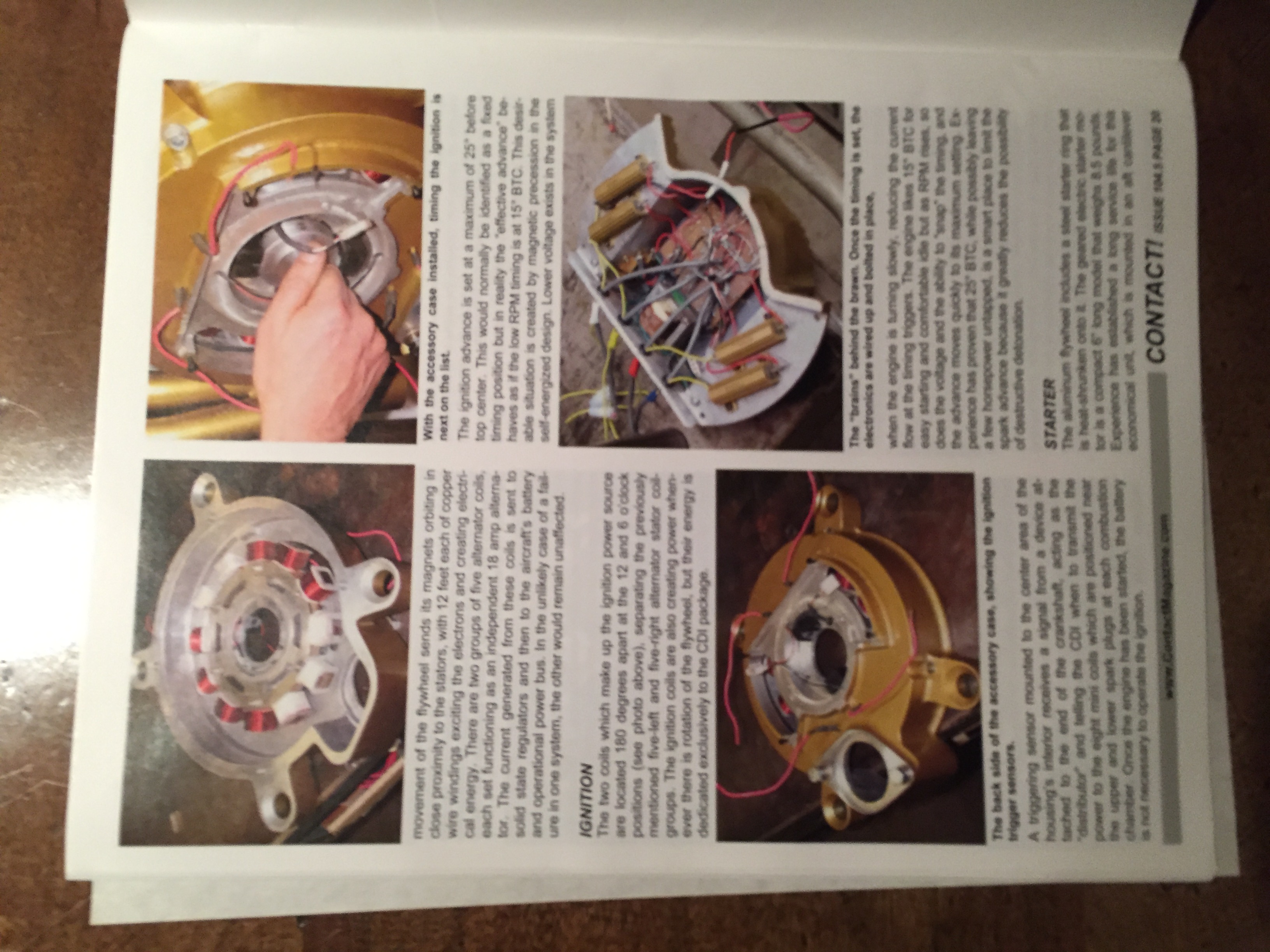
There are two pairs of wires exiting the accessory case. I believe they are all the same color. I've included pictures to show the schematic included in the instructions and pictures used in a contact magazine article about the engine. I don't want to reinvent the wheel here but would like to make sure I put this together the best way possible,  Concerns for me are the generators output to the battery which will be a EarthX Lithium. The ideal charging voltage is 13.9 - 14-6 V with 14.7V the maximum tolerated. I need to know if the TMG-3096 rectifier/regulator is suitable for the job or if there is a better choice available. What do I use to shut things down if the regulator fails. What else do I need to know. Â
Paul
On Tue, Jan 12, 2016 at 5:58 PM, user9253 <fransew(at)gmail.com (fransew(at)gmail.com)> wrote:
| Quote: | --> AeroElectric-List message posted by: "user9253" <fransew(at)gmail.com (fransew(at)gmail.com)>
How many wires come from the alternator, just two or two pairs? Are the wires marked or color coded? Do you have a picture of the rectifier/regulator? Can you post the schematic that you have?
--------
Joe Gores
Read this topic online here:
http://forums.matronics.com/viewtopic.php?p=451935#451935
===========
br> fts!)
r> > w.buildersbooks.com" rel="noreferrer" target="_blank">www.buildersbooks.com
rel="noreferrer" target="_blank">http://www.matronics.com/contribution
     -Matt Dralle, List Admin.
===========
-
Electric-List" rel="noreferrer" target="_blank">http://www.matronics.com/Navigator?AeroElectric-List
===========
FORUMS -
eferrer" target="_blank">http://forums.matronics.com
===========
b Site -
     -Matt Dralle, List Admin.
rel="noreferrer" target="_blank">http://www.matronics.com/contribution
===========
|
| | - The Matronics AeroElectric-List Email Forum - | | | Use the List Feature Navigator to browse the many List utilities available such as the Email Subscriptions page, Archive Search & Download, 7-Day Browse, Chat, FAQ, Photoshare, and much more:
http://www.matronics.com/Navigator?AeroElectric-List |
|
| Description: |
|
| Filesize: |
635.07 KB |
| Viewed: |
28103 Time(s) |

|
| Description: |
|
| Filesize: |
1.24 MB |
| Viewed: |
28103 Time(s) |
|
|
|
| Back to top |
|
|
user9253
Joined: 28 Mar 2008
Posts: 1974
Location: Riley TWP Michigan
|
| Posted: Wed Jan 13, 2016 5:38 pm Post subject: Re: Schematic for twin PM alternators |
|
|
Here is a link to an easy to read pdf of the Contact article that Paul mentioned above.

http://www.contactmagazine.com/Issue80/Issue-80L.pdf

Paul,

Looking at the Revmaster wiring picture, I am completely stumped.  I have no idea how it can work wired that way.  It appears that one of the AC wires is connected directly to the battery.  And why isn't the second alternator being utilized?  Most builders would love to have a second free alternator with no added weight.  All I can suggest is to call Revmaster and ask their advice.  If they offer no help, then I suggest that you use part of one of Bob Nuckolls' diagrams that contains a Dynamo with over-voltage protection.  He offers his book for download free.

http://www.aeroelectric.com/Book/AEC_R12A.pdf

If you can not figure out how to wire the regulator that you have, I suggest using the MIA881279 regulator available on eBay.
| | - The Matronics AeroElectric-List Email Forum - | | | Use the List Feature Navigator to browse the many List utilities available such as the Email Subscriptions page, Archive Search & Download, 7-Day Browse, Chat, FAQ, Photoshare, and much more:
http://www.matronics.com/Navigator?AeroElectric-List |
|
_________________
Joe Gores |
|
| Back to top |
|
|
ceengland7(at)gmail.com
Guest
|
| Posted: Wed Jan 13, 2016 7:59 pm Post subject: Schematic for twin PM alternators |
|
|
Agree that contacting Revmaster is the best 1st action. Ask for a real
schematic, in addition to the hookup cartoon. But the way I read the
drawing, they are showing 1/2 the system, with the other half 'implied'.
It looks like the alternator is wired to operate single phase, with one
end of the coil (actually three coils; unknown whether they are series
or parallel) having one end ground referenced and the other feeding a
diode contained within the regulator. The 'bat pos 12v DC' lead is
likely 14v, otherwise it won't charge the battery.
The book Joe references has a drawing that shows how to set up
overvoltage protection.
On 1/13/2016 7:38 PM, user9253 wrote:
| Quote: |
Here is a link to an easy to read pdf of the Contact article that Paul mentioned above.
http://www.contactmagazine.com/Issue80/Issue-80L.pdf
Paul,
Looking at the Revmaster wiring picture, I am completely stumped. I have no idea how it can work wired that way. It appears that one of the AC wires is connected directly to the battery. And why isn't the second alternator being utilized? Most builders would love to have a second free alternator with no added weight. All I can suggest is to call Revmaster and ask their advice. If they offer no help, then I suggest that you use part of one of Bob Nuckolls' diagrams that contains a Dynamo with over-voltage protection. He offers his book for download free.
http://www.aeroelectric.com/Book/AEC_R12A.pdf
If you can not figure out how to wire the regulator that you have, I suggest using the MIA881279 regulator available on eBay.
--------
Joe Gores
|
| | - The Matronics AeroElectric-List Email Forum - | | | Use the List Feature Navigator to browse the many List utilities available such as the Email Subscriptions page, Archive Search & Download, 7-Day Browse, Chat, FAQ, Photoshare, and much more:
http://www.matronics.com/Navigator?AeroElectric-List |
|
|
|
| Back to top |
|
|
wrbyars(at)aol.com
Guest
|
| Posted: Wed Jan 13, 2016 8:12 pm Post subject: Schematic for twin PM alternators |
|
|
I think you sent me this by mistake I don't know what you're talking about
On Jan 13, 2016 9:58 PM, Charlie England <ceengland7(at)gmail.com> wrote:
| Quote: |
Agree that contacting Revmaster is the best 1st action. Ask for a real
schematic, in addition to the hookup cartoon. But the way I read the
drawing, they are showing 1/2 the system, with the other half 'implied'.
It looks like the alternator is wired to operate single phase, with one
end of the coil (actually three coils; unknown whether they are series
or parallel) having one end ground referenced and the other feeding a
diode contained within the regulator. The 'bat pos 12v DC' lead is
likely 14v, otherwise it won't charge the battery.
The book Joe references has a drawing that shows how to set up
overvoltage protection.
On 1/13/2016 7:38 PM, user9253 wrote:
>
>
> Here is a link to an easy to read pdf of the Contact article that Paul mentioned above.
> http://www.contactmagazine.com/Issue80/Issue-80L.pdf
> Paul,
> Looking at the Revmaster wiring picture, I am completely stumped. I have no idea how it can work wired that way. It appears that one of the AC wires is connected directly to the battery. And why isn't the second alternator being utilized? Most builders would love to have a second free alternator with no added weight. All I can suggest is to call Revmaster and ask their advice. If they offer no help, then I suggest that you use part of one of Bob Nuckolls' diagrams that contains a Dynamo with over-voltage protection. He offers his book for download free.
> http://www.aeroelectric.com/Book/AEC_R12A.pdf
> If you can not figure out how to wire the regulator that you have, I suggest using the MIA881279 regulator available on eBay.
>
> --------
> Joe Gores
>
|
| | - The Matronics AeroElectric-List Email Forum - | | | Use the List Feature Navigator to browse the many List utilities available such as the Email Subscriptions page, Archive Search & Download, 7-Day Browse, Chat, FAQ, Photoshare, and much more:
http://www.matronics.com/Navigator?AeroElectric-List |
|
|
|
| Back to top |
|
|
nuckolls.bob(at)aeroelect
Guest
|
| Posted: Thu Jan 14, 2016 1:07 pm Post subject: Schematic for twin PM alternators |
|
|
At 09:58 PM 1/13/2016, you wrote:
| Quote: | --> AeroElectric-List message posted by: Charlie England <ceengland7(at)gmail.com>
Agree that contacting Revmaster is the best 1st action. Ask for a real schematic, in addition to the hookup cartoon. But the way I read the drawing, they are showing 1/2 the system, with the other half 'implied'. |
Agreed . . . I'm not sure 'we know what we don't know' about
this system. I've e-mailed Revmaster requesting copies of the
installation manuals for their full line of products for
l my library.
Bob . . .
| | - The Matronics AeroElectric-List Email Forum - | | | Use the List Feature Navigator to browse the many List utilities available such as the Email Subscriptions page, Archive Search & Download, 7-Day Browse, Chat, FAQ, Photoshare, and much more:
http://www.matronics.com/Navigator?AeroElectric-List |
|
|
|
| Back to top |
|
|
N509RV(at)eckenroth.com
Guest
|
| Posted: Thu Jan 14, 2016 2:03 pm Post subject: Schematic for twin PM alternators |
|
|
Joe  Thanks for the links. I see a number of schematics for PM alternator based systems. I need to study each and then make a list of components and questions. I'm sure that what I need will be based on what has already been done. Charlie is right that the other alternator hook up is same as what is shown. Bob is asking about manuals. I don't think that either Sonex or Revmaster has manuals beyond the very basic. I believe they both use a non-adjustable rectifier/regulator with no further controls other than fuse and switch. Â
Paul
On Thu, Jan 14, 2016 at 4:03 PM, Robert L. Nuckolls, III <nuckolls.bob(at)aeroelectric.com (nuckolls.bob(at)aeroelectric.com)> wrote:
| Quote: | At 09:58 PM 1/13/2016, you wrote:
| Quote: | --> AeroElectric-List message posted by: Charlie England <ceengland7(at)gmail.com (ceengland7(at)gmail.com)>
Agree that contacting Revmaster is the best 1st action. Ask for a real schematic, in addition to the hookup cartoon. But the way I read the drawing, they are showing 1/2 the system, with the other half 'implied'. |
 Agreed . . . I'm not sure 'we know what we don't know' about
 this system. I've e-mailed Revmaster requesting copies of the
 installation manuals for their full line of products for
l my library.
 Bob . . .
|
| | - The Matronics AeroElectric-List Email Forum - | | | Use the List Feature Navigator to browse the many List utilities available such as the Email Subscriptions page, Archive Search & Download, 7-Day Browse, Chat, FAQ, Photoshare, and much more:
http://www.matronics.com/Navigator?AeroElectric-List |
|
|
|
| Back to top |
|
|
nuckolls.bob(at)aeroelect
Guest
|
| Posted: Fri Jan 15, 2016 6:54 am Post subject: Schematic for twin PM alternators |
|
|
At 04:02 PM 1/14/2016, you wrote:
| Quote: | | Joe  Thanks for the links. I see a number of schematics for PM alternator based systems. I need to study each and then make a list of components and questions. I'm sure that what I need will be based on what has already been done. Charlie is right that the other alternator hook up is same as what is shown. Bob is asking about manuals. I don't think that either Sonex or Revmaster has manuals beyond the very basic. I believe they both use a non-adjustable rectifier/regulator with no further controls other than fuse and switch.  |
It appears that Revmaster has incorporated
TWO stator windings not unlike those on the
Rotax 912/914. Further, I read references
to alternator outputs of 18A and 18A, and 30A
in another place.
When offering this 'novel' product, it is
incumbent on the producer to describe its
capabilities, limits and recommended
integration techniques.
It's pretty cool that the manufacturer
has been able to up-size their DC generation
capabilities . . . the 912/914 has been
sota gasping for watts since day-one. On
the other hand, just how one integrates
TWO separate sources is unclear.
Does anyone on the List have a factory
installation manual for this engine? Those
excerpts in Contact are, as some have noted,
more confusing than illuminating.
I will suggest that studying anything published
in the 'Connection will be of limited value
until we understand exactly what's installed
on the engine and how the manufacturer intended
that it be used.
Bob . . .
| | - The Matronics AeroElectric-List Email Forum - | | | Use the List Feature Navigator to browse the many List utilities available such as the Email Subscriptions page, Archive Search & Download, 7-Day Browse, Chat, FAQ, Photoshare, and much more:
http://www.matronics.com/Navigator?AeroElectric-List |
|
|
|
| Back to top |
|
|
user9253
Joined: 28 Mar 2008
Posts: 1974
Location: Riley TWP Michigan
|
| Posted: Fri Jan 15, 2016 8:11 am Post subject: Re: Schematic for twin PM alternators |
|
|
Attached is a drawing that I made of a possible way to wire the Revmaster dynamo. It is based on limited information available about the Revmaster. Suggestions and criticism welcome (as long as you are not too hard on me).
| | - The Matronics AeroElectric-List Email Forum - | | | Use the List Feature Navigator to browse the many List utilities available such as the Email Subscriptions page, Archive Search & Download, 7-Day Browse, Chat, FAQ, Photoshare, and much more:
http://www.matronics.com/Navigator?AeroElectric-List |
|
| Description: |
|

Download |
| Filename: |
Revmaster.dwg |
| Filesize: |
144.68 KB |
| Downloaded: |
938 Time(s) |
| Description: |
|
Download |
| Filename: |
Revmaster.pdf |
| Filesize: |
48.11 KB |
| Downloaded: |
1011 Time(s) |
_________________
Joe Gores |
|
| Back to top |
|
|
N509RV(at)eckenroth.com
Guest
|
| Posted: Fri Jan 15, 2016 2:41 pm Post subject: Schematic for twin PM alternators |
|
|
I do have the Revmaster installation manual and the picture previously sent of the stator connections to the rectifier/regulator is the only reference to wiring the alternators. I believe it is intended that both alternators feed the battery at the same time. I do have a few questions:
What is the downside of both alternators connected to the battery at the same time.
What is the purpose of the capacitor.
If the crowbar disconnects a generator from the battery what happens. Is there any harm to the generator.
Paul
Â
On Fri, Jan 15, 2016 at 9:52 AM, Robert L. Nuckolls, III <nuckolls.bob(at)aeroelectric.com (nuckolls.bob(at)aeroelectric.com)> wrote:
| Quote: | At 04:02 PM 1/14/2016, you wrote:
| Quote: | | Joe à Thanks for the links.àI see a number of schematics for PM alternator based systems.àI need to study each and then make a list of components and questions.àI'm sure that what I need will be based on what has already been done.àCharlie is right that the other alternator hook up is same as what is shown.àBob is asking about manuals.àI don't think that either Sonex or Revmaster has manuals beyond the very basic.àI believe they both use a non-adjustable rectifier/regulator with no further controls other than fuse and switch. à |
 It appears that Revmaster has incorporated
 TWO stator windings not unlike those on the
 Rotax 912/914. Further, I read references
 to alternator outputs of 18A and 18A, and 30A
 in another place.
 When offering this 'novel' product, it is
 incumbent on the producer to describe its
 capabilities, limits and recommended
 integration techniques.
 It's pretty cool that the manufacturer
 has been able to up-size their DC generation
 capabilities . . . the 912/914 has been
 sota gasping for watts since day-one. On
 the other hand, just how one integrates
 TWO separate sources is unclear.
 Does anyone on the List have a factory
 installation manual for this engine? Those
 excerpts in Contact are, as some have noted,
 more confusing than illuminating.
 I will suggest that studying anything published
 in the 'Connection will be of limited value
 until we understand exactly what's installed
 on the engine and how the manufacturer intended
 that it be used.
 Bob . . .
|
| | - The Matronics AeroElectric-List Email Forum - | | | Use the List Feature Navigator to browse the many List utilities available such as the Email Subscriptions page, Archive Search & Download, 7-Day Browse, Chat, FAQ, Photoshare, and much more:
http://www.matronics.com/Navigator?AeroElectric-List |
|
|
|
| Back to top |
|
|
user9253
Joined: 28 Mar 2008
Posts: 1974
Location: Riley TWP Michigan
|
| Posted: Fri Jan 15, 2016 5:22 pm Post subject: Re: Schematic for twin PM alternators |
|
|
| Quote: | | What is the downside of both alternators connected to the battery at the same time. |
If the outputs from both alternators are exactly in phase with each other, then I suppose that they could be connected in parallel to a rectifier/regulator. The alternators may very well be in phase (if the wires are not connected backwards) because they are excited by the same rotating magnets. I do not understand how the alternators are connected to the rectifier/regulator in the picture that you posted. AC voltage can not be connected directly to a battery. The AC needs to be rectified and regulated first. The alternator coils can be damaged if not wired correctly. The trial and error method should not be used.
| Quote: | | What is the purpose of the capacitor. |
The output voltage from a rectifier/regulator is pulsing DC. A capacitor tries to smooth out the pulses. A flywheel on an engine is analogous to a capacitor in a circuit. They each smooth out pulses.
| Quote: | | If the crowbar disconnects a generator from the battery what happens. Is there any harm to the generator. |
I do not think so, but will leave that for others to answer.
| | - The Matronics AeroElectric-List Email Forum - | | | Use the List Feature Navigator to browse the many List utilities available such as the Email Subscriptions page, Archive Search & Download, 7-Day Browse, Chat, FAQ, Photoshare, and much more:
http://www.matronics.com/Navigator?AeroElectric-List |
|
_________________
Joe Gores |
|
| Back to top |
|
|
user9253
Joined: 28 Mar 2008
Posts: 1974
Location: Riley TWP Michigan
|
| Posted: Sat Jan 16, 2016 9:06 am Post subject: Re: Schematic for twin PM alternators |
|
|
Interesting blog about connecting home generators in parallel:

http://yarchive.net/car/rv/generator_synchronization.html

Most of the cautions and concerns described in that blog do not

apply to the Revmaster alternator because the relative speed

(frequency & voltage) and phase angle between the two windings

never changes, due to the common permanent-magnet field.

  Before connecting the Revmaster alternator windings in parallel, it must be determined that the two windings are in phase and not out of phase.

The blog describes how to do that.
| | - The Matronics AeroElectric-List Email Forum - | | | Use the List Feature Navigator to browse the many List utilities available such as the Email Subscriptions page, Archive Search & Download, 7-Day Browse, Chat, FAQ, Photoshare, and much more:
http://www.matronics.com/Navigator?AeroElectric-List |
|
_________________
Joe Gores |
|
| Back to top |
|
|
nuckolls.bob(at)aeroelect
Guest
|
| Posted: Sat Jan 16, 2016 9:35 am Post subject: Schematic for twin PM alternators |
|
|
| Quote: | I will suggest that studying anything published
in the 'Connection will be of limited value
until we understand exactly what's installed
on the engine and how the manufacturer intended
that it be used. |
All creative endeavors boil down to two
avenues of study. Whether you're crafting
a new dish in the kitchen or designing a
new engine, it all comes down to properties
of materials and management of energy.
The energy considerations for the Revmaster dual
alternator windings includes questions like
are the two outputs in phase with each other?
Are they the same magnitude? If so, the
system integrator might consider simply paralleling
the two windings and feeding them into a VERY robust
rectifier-regulator . . . I think there are some
small tractor products that are rated in the
30-35A class . . . a pair of 18A stators would
challenge such a device . . . if they even
exist.
A low-risk approach would be to treat the two
as separate alternators each fitted with its
own r-r. Okay, now you have to decide if
the two outputs will be simply paralled to the
same bus . . . or perhaps configured as a 'mini-
Z14" system. One of the two might drive the
main battery . . . the second could be paired
with a similar or smaller battery.
A energy study on installed dual alternators
would explore whether they are sufficiently
matched to simply parallel to a single battery/
bus. This is probably the most attractive
option for a small airplane. You would want
to load the system well into the upper regions
of capability and check to see that both
systems do a reasonable job of sharing loads.
Revmaster probably has test stands where
they can run a fully appointed engine. THEY
of all individuals are BEST situated to ponder
these and other questions. The answers would
illuminate the path to one or more practical
ways their product can be integrated into OBAM
aircraft . . .
I'll rattle their cage a bit and see if they
have already done any studies . . . or are
prepared to do them. Once that engine is bolted
to an TC airplane, the $time$ to develop the
optimal system goes up by a factor of four
to twenty times. In OBAM aviation, it's worse.
TC aircraft fixes can be propagated through
the fleet with some order of dispatch . . .
The OBAM community might re-invent the same
or similar wheels over and over again. A
needless and perhaps even hazardous waste
of time, talent and resources.
This is not a new thing nor is it unique to
OBAM aviation. Companies I've worked for have
suffered $millions$ in expense and untold damage to
customer loyalty doing development work on
fielded aircraft . . . it never turns out well.
Note to Revmaster . . . NOW is the time guys . . .
YOU need to be doing this . . .
Bob . . .
| | - The Matronics AeroElectric-List Email Forum - | | | Use the List Feature Navigator to browse the many List utilities available such as the Email Subscriptions page, Archive Search & Download, 7-Day Browse, Chat, FAQ, Photoshare, and much more:
http://www.matronics.com/Navigator?AeroElectric-List |
|
|
|
| Back to top |
|
|
N509RV(at)eckenroth.com
Guest
|
| Posted: Sat Jan 16, 2016 10:53 am Post subject: Schematic for twin PM alternators |
|
|
I don't understand the comment about the two generators being in or out of phase. If they are both run through a rectifier.regulator wouldn't that eliminate the phase concern.I looked at a schematic for a Lockwood AirCam. This has two Rotax engines each with magneto, rectifier/regulator, and capacitor all tied into one battery.
Paul
On Fri, Jan 15, 2016 at 8:22 PM, user9253 <fransew(at)gmail.com (fransew(at)gmail.com)> wrote:
| Quote: | --> AeroElectric-List message posted by: "user9253" <fransew(at)gmail.com (fransew(at)gmail.com)>
> What is the downside of both alternators connected to the battery at the same time.
If the outputs from both alternators are exactly in phase with each other, then I suppose that they could be connected in parallel to a rectifier/regulator. The alternators may very well be in phase (if the wires are not connected backwards) because they are excited by the same rotating magnets. I do not understand how the alternators are connected to the rectifier/regulator in the picture that you posted. AC voltage can not be connected directly to a battery. The AC needs to be rectified and regulated first. The alternator coils can be damaged if not wired correctly. The trial and error method should not be used.
> What is the purpose of the capacitor.
The output voltage from a rectifier/regulator is pulsing DC. A capacitor tries to smooth out the pulses. A flywheel on an engine is analogous to a capacitor in a circuit. They each smooth out pulses.
> If the crowbar disconnects a generator from the battery what happens. Is there any harm to the generator.
I do not think so, but will leave that for others to answer.
--------
Joe Gores
Read this topic online here:
http://forums.matronics.com/viewtopic.php?p=452010#452010
===========
br> fts!)
r> > w.buildersbooks.com" rel="noreferrer" target="_blank">www.buildersbooks.com
rel="noreferrer" target="_blank">http://www.matronics.com/contribution
     -Matt Dralle, List Admin.
===========
-
Electric-List" rel="noreferrer" target="_blank">http://www.matronics.com/Navigator?AeroElectric-List
===========
FORUMS -
eferrer" target="_blank">http://forums.matronics.com
===========
b Site -
     -Matt Dralle, List Admin.
rel="noreferrer" target="_blank">http://www.matronics.com/contribution
===========
|
| | - The Matronics AeroElectric-List Email Forum - | | | Use the List Feature Navigator to browse the many List utilities available such as the Email Subscriptions page, Archive Search & Download, 7-Day Browse, Chat, FAQ, Photoshare, and much more:
http://www.matronics.com/Navigator?AeroElectric-List |
|
|
|
| Back to top |
|
|
|
|
You cannot post new topics in this forum
You cannot reply to topics in this forum
You cannot edit your posts in this forum
You cannot delete your posts in this forum
You cannot vote in polls in this forum
You cannot attach files in this forum
You can download files in this forum
|
Powered by phpBB © 2001, 2005 phpBB Group
|

