 |
Matronics Email Lists
Web Forum Interface to the Matronics Email Lists
|
| View previous topic :: View next topic |
| Author |
Message |
fvalarm(at)rapidnet.net
Guest
|
 Posted: Mon Apr 11, 2016 10:39 pm Post subject: RF Interference Posted: Mon Apr 11, 2016 10:39 pm Post subject: RF Interference |
 |
|
Here's a challenge for the brains.

Suddenly my fuel pressure indication has become the victim of RF interference.  I've had the airplane off-line for some mods and upgrades and during this time has come down with a severe case of RF-itis.

Symptoms:

When I push the PTT, the fuel pressure indication steadily climbs as a rate of about 5 psi/second as long as it's maintained all the way to 60 PSI (engine and fuel pump off).  This occurs with either comm radio (each has it's own antenna, feed line and routing), although one radio only gets the error up to about 30-40 PSI.  A handheld has a similar effect but to a lesser degree presumably because it has less transmit power.

Note;  ATC has no problem hearing my transmissions with either radio.

Things that I have changed since taking the airplane off-line when everything had been working fine:

A) Replaced one comm antenna (bent whip on fuselage bottom) with a new straight antenna installed on the rear turtle deck.  This required extending the coax with BNC and RG400 cable.  This is the radio/antenna combination that has the lesser effect on the fuel pressure reading.  The other radio/antenna system was not modified in any way. This radio has the larger effect on the fuel pressure reading.

B) Added a VHF tracker radio which transmits a "bread-crumb" every 120 seconds.

C) The engine monitor was sent to the factory for a software upgrade that wasn't needed after all and therefore nothing was done and re-installed.

Equipment:

A) The fuel pressure sender is GRT's HPS-SS-01 which has three wires and a 4th (shield) not to be connected.  Details here...

http://www.grtavionics.com/documents/EIS/100%20psi%20SS%2012V%20Pressure%20Sensor.pdf

I suspect this transducer has some electronics inside that are possibly affected by RF in turn sending an erroneous reading out to the engine monitor.

B) Engine monitor is GRT's EIS 4000.

What I have done so far...

A) Installed ferrite cores (6 so far) around all the wires coming out of the sender, at the sender.  This has caused the RF interference to be dramatically reduced to a 4-6 PSI change (depending on which radio) while in the hangar, but in the air, the interference still steadily climbs with application of PTT.  The output voltage on the signal wire (disconnected from the engine monitor) sits idle at 1 volt but climbs steadily to over 4 volts with PTT/RF.  The ferrite cores hold the voltage rise to about 200 mV.

B) I spoke to tech support at GRT today.  They said if anything, put the ferrite core around just the sender's signal wire where it goes into the engine monitor.  I installed one ferrite core there today (leaving all the others in place) and this had no noticeable effect in the hangar.  I think the RF is affecting the sender, not the monitor.

C) The problem occurs whether the VHF tracker is turned on or not.  I even took the fuse out so this system has nothing connected to the power bus.  I have not removed the antenna however to see if it is somehow coupling the comm's RF into the airframe via the ground wire.  Is this possible?  The radio that has the largest effect has it's antenna closest to the tracker antenna on the fuse bottom.  The VHF tracker works as advertised.

Questions:

What is going on here?

Is it likely to be a sender has suddenly gone bad?

What about that shield wire that comes out of the sender that is not to be connected to anything?  What good is it if not connected to anything?  The wiring is not shielded between the sender and the engine monitor.  The sender's wiring was not modified in anyway during the aircraft's upgrades.

Is the Tracker's antenna feeding RF back into the airframe?

Any other ideas?


 Bevan
| | - The Matronics AeroElectric-List Email Forum - | | | Use the List Feature Navigator to browse the many List utilities available such as the Email Subscriptions page, Archive Search & Download, 7-Day Browse, Chat, FAQ, Photoshare, and much more:
http://www.matronics.com/Navigator?AeroElectric-List |
|
|
|
| Back to top |
|
 |
nuckolls.bob(at)aeroelect
Guest
|
| Posted: Tue Apr 12, 2016 7:33 am Post subject: RF Interference |
|
|
B) Engine monitor is GRT's EIS 4000.


 What I have done so far...


 A) Installed ferrite cores (6 so far) around all the wires coming out of the sender, at the sender.  This has caused the RF interference to be dramatically reduced to a 4-6 PSI change (depending on which radio) while in the hangar, but in the air, the interference still steadily climbs with application of PTT.  The output voltage on the signal wire (disconnected from the engine monitor) sits idle at 1 volt but climbs steadily to over 4 volts with PTT/RF.  The ferrite cores hold the voltage rise to about 200 mV.


     EMI interference mitigation with the

     ferrite cores is a bit iffy . . . it's

     also dependent on what kind of ferrite.

     Ferrite for radio frequency inductors and

     transformers is optimized for minimum

     losses while ferrites for converting stray

     energies to heat are designed to exhibit

     losses.


     High quality ferrites can be components

     of a filter network of an inductor and one

     or more capacitors.


 B) I spoke to tech support at GRT today.  They said if anything, put the ferrite core around just the sender's signal wire where it goes into the engine monitor.  I installed one ferrite core there today (leaving all the others in place) and this had no noticeable effect in the hangar.  I think the RF is affecting the sender, not the monitor.


     Good supposition.


 C) The problem occurs whether the VHF tracker is turned on or not.  I even took the fuse out so this system has nothing connected to the power bus.  I have not removed the antenna however to see if it is somehow coupling the comm's RF into the airframe via the ground wire.  Is this possible?  The radio that has the largest effect has it's antenna closest to the tracker antenna on the fuse bottom.  The VHF tracker works as advertised.


 Questions:


 What is going on here?


 Is it likely to be a sender has suddenly gone bad?


    Not likely . . .


 What about that shield wire that comes out of the sender that is not to be connected to anything?  What good is it if not connected to anything?  The wiring is not shielded between the sender and the engine monitor.  The sender's wiring was not modified in anyway during the aircraft's upgrades.


 Is the Tracker's antenna feeding RF back into the airframe?


    Probably not. Can you tell me who makes

    the pressure transducer and what its part

    number is?


    I may have a 'fix' but I need more data before

    I can recommend it with any confidence.


   Bob . . .
| | - The Matronics AeroElectric-List Email Forum - | | | Use the List Feature Navigator to browse the many List utilities available such as the Email Subscriptions page, Archive Search & Download, 7-Day Browse, Chat, FAQ, Photoshare, and much more:
http://www.matronics.com/Navigator?AeroElectric-List |
|
|
|
| Back to top |
|
|
fvalarm(at)rapidnet.net
Guest
|
| Posted: Tue Apr 12, 2016 8:42 am Post subject: RF Interference |
|
|
Hi Bob,


 I believe this is the sender...


 MSP 300-100-P-4-A-1   see...


 http://www.mouser.com/ds/2/418/MSP300-769580.pdf


 Thanks.


 I'm going out to the hangar to remove the VHF Tracker  antenna and re-test to try and rule out that path back into the aircraft.   Will report back soon.


 Bevan


   From:  owner-aeroelectric-list-server(at)matronics.com  [mailto:owner-aeroelectric-list-server(at)matronics.com] On Behalf Of Robert  L. Nuckolls, III

Sent: Tuesday, April 12, 2016 8:32 AM

To:  aeroelectric-list(at)matronics.com

Subject: Re: RF  Interference


B) Engine monitor is GRT's EIS 4000.


What I have  done so far...


A) Installed ferrite cores (6 so far) around all the  wires coming out of the sender, at the sender.  This has caused the RF  interference to be dramatically reduced to a 4-6 PSI change (depending on which  radio) while in the hangar, but in the air, the interference still steadily  climbs with application of PTT.  The output voltage on the signal wire  (disconnected from the engine monitor) sits idle at 1 volt but climbs steadily  to over 4 volts with PTT/RF.  The ferrite cores hold the voltage rise to  about 200 mV.


    EMI interference mitigation with  the

    ferrite cores is a bit iffy . . .  it's

    also dependent on what kind of  ferrite.

    Ferrite for radio frequency inductors  and

    transformers is optimized for  minimum

    losses while ferrites for converting  stray

    energies to heat are designed to  exhibit

    losses.


    High quality  ferrites can be components

    of a filter network of an  inductor and one

    or more capacitors.


B) I spoke  to tech support at GRT today.  They said if anything, put the ferrite core  around just the sender's signal wire where it goes into the engine  monitor.  I installed one ferrite core there today (leaving all the others  in place) and this had no noticeable effect in the hangar.  I think the RF  is affecting the sender, not the monitor.


     Good supposition.


C) The problem occurs whether the VHF tracker  is turned on or not.  I even took the fuse out so this system has nothing  connected to the power bus.  I have not removed the antenna however to see  if it is somehow coupling the comm's RF into the airframe via the ground  wire.  Is this possible?  The radio that has the largest effect has  it's antenna closest to the tracker antenna on the fuse bottom.  The VHF  tracker works as advertised.


Questions:


What is  going on here?


Is it likely to be a sender has suddenly gone  bad?


   Not likely . . .


What  about that shield wire that comes out of the sender that is not to be connected  to anything?  What good is it if not connected to anything?  The  wiring is not shielded between the sender and the engine monitor.  The  sender's wiring was not modified in anyway during the aircraft's  upgrades.


Is the Tracker's antenna feeding RF back into the  airframe?


   Probably not. Can you tell me who  makes

   the pressure transducer and what its part

    number is?


   I may have a 'fix' but I need more data  before

   I can recommend it with any confidence.


  Bob . . .
| | - The Matronics AeroElectric-List Email Forum - | | | Use the List Feature Navigator to browse the many List utilities available such as the Email Subscriptions page, Archive Search & Download, 7-Day Browse, Chat, FAQ, Photoshare, and much more:
http://www.matronics.com/Navigator?AeroElectric-List |
|
|
|
| Back to top |
|
|
user9253
Joined: 28 Mar 2008
Posts: 1972
Location: Riley TWP Michigan
|
| Posted: Tue Apr 12, 2016 10:12 am Post subject: Re: RF Interference |
|
|
It is common practice to connect a shield at one end only, however follow the manufacturer's recommendation.  Assuming that the sender's wires have been extended, here are some suggestions:

1. Twist the extension wires together.  An easy way to do that is to chuck the wire ends in a drill.

2. Use shielded extension wire with the shield grounded at one end only.  Do not connect the two shields together.

3. Loop the wire at the sender end with the loop going through a ferrite bead.
| | - The Matronics AeroElectric-List Email Forum - | | | Use the List Feature Navigator to browse the many List utilities available such as the Email Subscriptions page, Archive Search & Download, 7-Day Browse, Chat, FAQ, Photoshare, and much more:
http://www.matronics.com/Navigator?AeroElectric-List |
|
_________________
Joe Gores |
|
| Back to top |
|
|
fvalarm(at)rapidnet.net
Guest
|
| Posted: Tue Apr 12, 2016 11:20 am Post subject: RF Interference |
|
|
Ok,  Just got back from the hangar.


Just now I removed the VHF Tracker antenna, disconnected all new wires going

in/out of the tracker and hit the PTT.  No change.  I'm still getting a 5

PSI rise in fuel pressure (engine and boost pump off so pressure should

remain at zero).  I still have the ferrite cores installed at the fuel

pressure sender.  Without them, the pressure would climb to 60 PSI if I held

the PTT long enough.  I feel I can now rule out the tracker.


Just to recap, the high fuel pressure anomaly has not been a problem for the

first 40 hours of flying.  It has come on suddenly since I put the airplane

down for maintenance/upgrades (tracker install, new comm antenna/location

for comm 1, New OAT sender and location, plus a few other non-electrical

items).


I will focus on the OAT sender next.  It was a plastic jobber inside the

wing root.  I never should have put it there in the first place.  I just did

as suggested.  I have moved it to under the wing on the first inspection

panel.  It is now a SS version which protrudes through the skin.  It feeds a

signal back to the engine monitor (EIS4000).  It has a ground wire and a

signal wire.


Bevan


--
| | - The Matronics AeroElectric-List Email Forum - | | | Use the List Feature Navigator to browse the many List utilities available such as the Email Subscriptions page, Archive Search & Download, 7-Day Browse, Chat, FAQ, Photoshare, and much more:
http://www.matronics.com/Navigator?AeroElectric-List |
|
|
|
| Back to top |
|
|
user9253
Joined: 28 Mar 2008
Posts: 1972
Location: Riley TWP Michigan
|
| Posted: Tue Apr 12, 2016 12:02 pm Post subject: Re: RF Interference |
|
|
Where is the fuel pressure sender grounded at? It should be grounded at the display unit, not locally.
| | - The Matronics AeroElectric-List Email Forum - | | | Use the List Feature Navigator to browse the many List utilities available such as the Email Subscriptions page, Archive Search & Download, 7-Day Browse, Chat, FAQ, Photoshare, and much more:
http://www.matronics.com/Navigator?AeroElectric-List |
|
_________________
Joe Gores |
|
| Back to top |
|
|
fvalarm(at)rapidnet.net
Guest
|
| Posted: Tue Apr 12, 2016 12:20 pm Post subject: RF Interference |
|
|
The sender is grounded where it always has been, at the forest of tabs,

single point ground point.


Thanks.


Bevan


--
| | - The Matronics AeroElectric-List Email Forum - | | | Use the List Feature Navigator to browse the many List utilities available such as the Email Subscriptions page, Archive Search & Download, 7-Day Browse, Chat, FAQ, Photoshare, and much more:
http://www.matronics.com/Navigator?AeroElectric-List |
|
|
|
| Back to top |
|
|
nuckolls.bob(at)aeroelect
Guest
|
| Posted: Tue Apr 12, 2016 1:34 pm Post subject: RF Interference |
|
|
MSP transducers are generally pretty EMC robust. It's still
a mystery as to what might have changed . . . but
here's an experiment you can run to help divide
and conquer.
Take an AA alkaline cell and solder some 'pigtails'
to the + and - terminals. Disconnect the tranducer
at the engine end of the wiring and hook the
aa battery + to white, - to black leads running
back to the panel.
Take ferrites off if convenient . . .
See what your EIS system reads . . . should
be on the order of 50 pounds. The key a transmitter
to observe effects. If the readings are now steady,
then the interference is upsetting the transducer.
If the problem persists, then the real victim
is the EIS panel box.
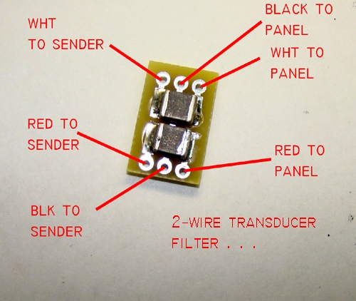
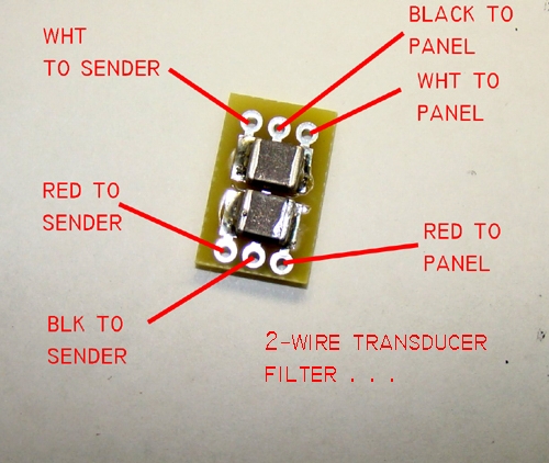
I can send you an itty-bitty filter that wires into the
transducer leads within short distance of the
victim as identified by experiment . . .
[img]cid:.0[/img]
What are the wires between the EIS panel connector
and the transducer? It would be good if they were a
twisted trio with all panel end wires terminated
at the EIS connector.
Bob . . .
| | - The Matronics AeroElectric-List Email Forum - | | | Use the List Feature Navigator to browse the many List utilities available such as the Email Subscriptions page, Archive Search & Download, 7-Day Browse, Chat, FAQ, Photoshare, and much more:
http://www.matronics.com/Navigator?AeroElectric-List |
|
| Description: |
|
| Filesize: |
158.97 KB |
| Viewed: |
16813 Time(s) |

|
|
|
| Back to top |
|
|
fvalarm(at)rapidnet.net
Guest
|
| Posted: Tue Apr 12, 2016 2:23 pm Post subject: RF Interference |
|
|
Those are excellent ideas Bob,


 I will do the AA thing and report back.  Hold off on the  filter for now.


 Regarding the wires between the EIS and  sender...


 The EIS powers the sender.  Red wire.


 The sender gets it's ground from the forest of tabs nearby so  the red/black are not twisted the whole way but this has not changed since day  one.


 The white signal wire is twisted with the mix all the way back  to the EIS.


 What is the proper way and position to input the ferrite cores  (cylinders)?  Currently I have the cores at the sender with all three wires  going straight through some of the cores, and several times through  others.  6 total.  Each ferrite core reduced the effect an  approximate equal amount from 60 PSI down to 6PSI.  Adding one more  just around the signal wire at the EIS did nothing more.


 Bevan


   From:  owner-aeroelectric-list-server(at)matronics.com  [mailto:owner-aeroelectric-list-server(at)matronics.com] On Behalf Of Robert  L. Nuckolls, III

Sent: Tuesday, April 12, 2016 2:33 PM

To:  aeroelectric-list(at)matronics.com

Subject: RE: Re: RF  Interference


MSP transducers are generally pretty EMC robust. It's  still

a mystery as to what might have changed . . . but

here's an  experiment you can run to help divide

and conquer.


Take an AA alkaline  cell and solder some 'pigtails'

to the + and - terminals. Disconnect the  tranducer

at the engine end of the wiring and hook the

aa battery + to  white, - to black leads running

back to the panel.


Take ferrites off  if convenient . . .


See what your EIS system reads . . . should

be on  the order of 50 pounds. The key a transmitter

to observe effects.  If  the readings are now steady,

then the interference is upsetting the  transducer.

If the problem persists, then the real victim

is the EIS panel  box.


I can send you an itty-bitty filter that wires into the

transducer leads within short distance of the

victim as identified by  experiment . . .

[img]cid:468541322(at)12042016-1608[/img]


What are the wires between the EIS panel  connector

and the transducer? It would be good if they were a

twisted trio  with all panel end wires terminated

at the EIS connector.


  Bob . . .
| | - The Matronics AeroElectric-List Email Forum - | | | Use the List Feature Navigator to browse the many List utilities available such as the Email Subscriptions page, Archive Search & Download, 7-Day Browse, Chat, FAQ, Photoshare, and much more:
http://www.matronics.com/Navigator?AeroElectric-List |
|
| Description: |
|
| Filesize: |
158.97 KB |
| Viewed: |
16813 Time(s) |

|
|
|
| Back to top |
|
|
ceengland7(at)gmail.com
Guest
|
| Posted: Tue Apr 12, 2016 3:16 pm Post subject: RF Interference |
|
|
| Quote: | I've got a vague memory of guys with top-mounted antennas having
'issues' with various components in their instrument panels, including
erratic autopilot behavior. No way to know from here what was actually
wrong, but it does raise a couple of questions.
Have you tried moving the comm ant feed back to the belly antenna?
(Improperly shielded components in the instrument panel can see a lot
more RF energy through the canopy than the belly skin.)
Have you verified continuity of the shield on the antenna coax all the
way to the new antenna, and verified that the shield is properly bonded
to the skin?
(IIRC, there have been issues with some a/c when the shield didn't get
properly bonded at the antenna location; basically turned the entire run
of coax into an RF radiator & gave multiple electronic devices within
the a/c fits.)
Charlie |
On 4/12/2016 5:21 PM, B Tomm wrote:
| Quote: | Those are excellent ideas Bob,
I will do the AA thing and report back. Hold off on the filter for now.
Regarding the wires between the EIS and sender...
The EIS powers the sender. Red wire.
The sender gets it's ground from the forest of tabs nearby so the red/black are not twisted the whole way but this has not changed since day one.
The white signal wire is twisted with the mix all the way back to the EIS.
What is the proper way and position to input the ferrite cores (cylinders)? Currently I have the cores at the sender with all three wires going straight through some of the cores, and several times through others. 6 total. Each ferrite core reduced the effect an approximate equal amount from 60 PSI down to 6PSI. Adding one more just around the signal wire at the EIS did nothing more.
Bevan
From: owner-aeroelectric-list-server(at)matronics.com (owner-aeroelectric-list-server(at)matronics.com) [mailto:owner-aeroelectric-list-server(at)matronics.com (owner-aeroelectric-list-server(at)matronics.com)] On Behalf Of Robert L. Nuckolls, III
Sent: Tuesday, April 12, 2016 2:33 PM
To: aeroelectric-list(at)matronics.com (aeroelectric-list(at)matronics.com)
Subject: RE: Re: RF Interference
MSP transducers are generally pretty EMC robust. It's still
a mystery as to what might have changed . . . but
here's an experiment you can run to help divide
and conquer.
Take an AA alkaline cell and solder some 'pigtails'
to the + and - terminals. Disconnect the tranducer
at the engine end of the wiring and hook the
aa battery + to white, - to black leads running
back to the panel.
Take ferrites off if convenient . . .
See what your EIS system reads . . . should
be on the order of 50 pounds. The key a transmitter
to observe effects. If the readings are now steady,
then the interference is upsetting the transducer.
If the problem persists, then the real victim
is the EIS panel box.
I can send you an itty-bitty filter that wires into the
transducer leads within short distance of the
victim as identified by experiment . . .
What are the wires between the EIS panel connector
and the transducer? It would be good if they were a
twisted trio with all panel end wires terminated
at the EIS connector.
Bob . . . |
| | - The Matronics AeroElectric-List Email Forum - | | | Use the List Feature Navigator to browse the many List utilities available such as the Email Subscriptions page, Archive Search & Download, 7-Day Browse, Chat, FAQ, Photoshare, and much more:
http://www.matronics.com/Navigator?AeroElectric-List |
|
|
|
| Back to top |
|
|
fvalarm(at)rapidnet.net
Guest
|
| Posted: Tue Apr 12, 2016 4:05 pm Post subject: RF Interference |
|
|
That's a very good point Charlie. I have not checked continuity of the shield. However, Comm2 has it's antenna also on the bottom, and was not changed in anyway during the upgrades. It has the largest effect.
I don't think the antennas contact the aircraft skin. There's a rubber gasket between the skin and the antenna that came with the antennas. Further, my aircraft is wrapped in vinyl (since day one) and the vinyl was applied with the antennas off so that's in between there too.
Bevan
From: owner-aeroelectric-list-server(at)matronics.com [mailto:owner-aeroelectric-list-server(at)matronics.com] On Behalf Of Charlie England
Sent: Tuesday, April 12, 2016 3:47 PM
To: aeroelectric-list(at)matronics.com
Subject: Re: Re: RF Interference
I've got a vague memory of guys with top-mounted antennas having 'issues' with various components in their instrument panels, including erratic autopilot behavior. No way to know from here what was actually wrong, but it does raise a couple of questions.
Have you tried moving the comm ant feed back to the belly antenna?
(Improperly shielded components in the instrument panel can see a lot more RF energy through the canopy than the belly skin.)
Have you verified continuity of the shield on the antenna coax all the way to the new antenna, and verified that the shield is properly bonded to the skin?
(IIRC, there have been issues with some a/c when the shield didn't get properly bonded at the antenna location; basically turned the entire run of coax into an RF radiator & gave multiple electronic devices within the a/c fits.)
Charlie
On 4/12/2016 5:21 PM, B Tomm wrote:
| Quote: | Those are excellent ideas Bob,
I will do the AA thing and report back. Hold off on the filter for now.
Regarding the wires between the EIS and sender...
The EIS powers the sender. Red wire.
The sender gets it's ground from the forest of tabs nearby so the red/black are not twisted the whole way but this has not changed since day one.
The white signal wire is twisted with the mix all the way back to the EIS.
What is the proper way and position to input the ferrite cores (cylinders)? Currently I have the cores at the sender with all three wires going straight through some of the cores, and several times through others. 6 total. Each ferrite core reduced the effect an approximate equal amount from 60 PSI down to 6PSI. Adding one more just around the signal wire at the EIS did nothing more.
Bevan
From: owner-aeroelectric-list-server(at)matronics.com (owner-aeroelectric-list-server(at)matronics.com) [mailto:owner-aeroelectric-list-server(at)matronics.com (owner-aeroelectric-list-server(at)matronics.com)] On Behalf Of Robert L. Nuckolls, III
Sent: Tuesday, April 12, 2016 2:33 PM
To: aeroelectric-list(at)matronics.com (aeroelectric-list(at)matronics.com)
Subject: RE: Re: RF Interference
MSP transducers are generally pretty EMC robust. It's still
a mystery as to what might have changed . . . but
here's an experiment you can run to help divide
and conquer.
Take an AA alkaline cell and solder some 'pigtails'
to the + and - terminals. Disconnect the tranducer
at the engine end of the wiring and hook the
aa battery + to white, - to black leads running
back to the panel.
Take ferrites off if convenient . . .
See what your EIS system reads . . . should
be on the order of 50 pounds. The key a transmitter
to observe effects. If the readings are now steady,
then the interference is upsetting the transducer.
If the problem persists, then the real victim
is the EIS panel box.
I can send you an itty-bitty filter that wires into the
transducer leads within short distance of the
victim as identified by experiment . . .
[img]cid:328085723(at)12042016-160F[/img]
What are the wires between the EIS panel connector
and the transducer? It would be good if they were a
twisted trio with all panel end wires terminated
at the EIS connector.
Bob . . . |
| | - The Matronics AeroElectric-List Email Forum - | | | Use the List Feature Navigator to browse the many List utilities available such as the Email Subscriptions page, Archive Search & Download, 7-Day Browse, Chat, FAQ, Photoshare, and much more:
http://www.matronics.com/Navigator?AeroElectric-List |
|
| Description: |
|
| Filesize: |
158.97 KB |
| Viewed: |
16813 Time(s) |
|
|
|
| Back to top |
|
|
Kellym
Joined: 10 Jan 2006
Posts: 1706
Location: Sun Lakes AZ
|
| Posted: Tue Apr 12, 2016 4:27 pm Post subject: RF Interference |
|
|
Normally com antennas ground via the mounting screws, so it doesn't
matter if the skin under the antenna is painted, gasketed or whatever.
Only the counter sink in the antenna and the nutplates and doubler on
underside need good grounding.
On 4/12/2016 5:01 PM, B Tomm wrote:
| Quote: | That's a very good point Charlie. I have not checked continuity of the
shield. However, Comm2 has it's antenna also on the bottom, and was not
changed in anyway during the upgrades. It has the largest effect.
I don't think the antennas contact the aircraft skin. There's a rubber
gasket between the skin and the antenna that came with the antennas.
Further, my aircraft is wrapped in vinyl (since day one) and the vinyl
was applied with the antennas off so that's in between there too.
Bevan
------------------------------------------------------------------------
*From:* owner-aeroelectric-list-server(at)matronics.com
[mailto:owner-aeroelectric-list-server(at)matronics.com] *On Behalf Of
*Charlie England
*Sent:* Tuesday, April 12, 2016 3:47 PM
*To:* aeroelectric-list(at)matronics.com
*Subject:* Re: Re: RF Interference
I've got a vague memory of guys with top-mounted antennas having
'issues' with various components in their instrument panels, including
erratic autopilot behavior. No way to know from here what was actually
wrong, but it does raise a couple of questions.
Have you tried moving the comm ant feed back to the belly antenna?
(Improperly shielded components in the instrument panel can see a lot
more RF energy through the canopy than the belly skin.)
Have you verified continuity of the shield on the antenna coax all the
way to the new antenna, and verified that the shield is properly bonded
to the skin?
(IIRC, there have been issues with some a/c when the shield didn't get
properly bonded at the antenna location; basically turned the entire run
of coax into an RF radiator & gave multiple electronic devices within
the a/c fits.)
Charlie
On 4/12/2016 5:21 PM, B Tomm wrote:
> Those are excellent ideas Bob,
> I will do the AA thing and report back. Hold off on the filter for now.
> Regarding the wires between the EIS and sender...
> The EIS powers the sender. Red wire.
> The sender gets it's ground from the forest of tabs nearby so the
> red/black are not twisted the whole way but this has not changed since
> day one.
> The white signal wire is twisted with the mix all the way back to the EIS.
> What is the proper way and position to input the ferrite cores
> (cylinders)? Currently I have the cores at the sender with all three
> wires going straight through some of the cores, and several times
> through others. 6 total. Each ferrite core reduced the effect an
> approximate equal amount from 60 PSI down to 6PSI. Adding one more
> just around the signal wire at the EIS did nothing more.
> Bevan
>
> ------------------------------------------------------------------------
> *From:* owner-aeroelectric-list-server(at)matronics.com
> [mailto:owner-aeroelectric-list-server(at)matronics.com] *On Behalf Of
> *Robert L. Nuckolls, III
> *Sent:* Tuesday, April 12, 2016 2:33 PM
> *To:* aeroelectric-list(at)matronics.com
> *Subject:* RE: Re: RF Interference
>
> MSP transducers are generally pretty EMC robust. It's still
> a mystery as to what might have changed . . . but
> here's an experiment you can run to help divide
> and conquer.
>
> Take an AA alkaline cell and solder some 'pigtails'
> to the + and - terminals. Disconnect the tranducer
> at the engine end of the wiring and hook the
> aa battery + to white, - to black leads running
> back to the panel.
>
> Take ferrites off if convenient . . .
>
> See what your EIS system reads . . . should
> be on the order of 50 pounds. The key a transmitter
> to observe effects. If the readings are now steady,
> then the interference is upsetting the transducer.
> If the problem persists, then the real victim
> is the EIS panel box.
>
> I can send you an itty-bitty filter that wires into the
> transducer leads within short distance of the
> victim as identified by experiment . . .
> Emacs!
>
> What are the wires between the EIS panel connector
> and the transducer? It would be good if they were a
> twisted trio with all panel end wires terminated
> at the EIS connector.
>
> Bob . . .
>
|
| | - The Matronics AeroElectric-List Email Forum - | | | Use the List Feature Navigator to browse the many List utilities available such as the Email Subscriptions page, Archive Search & Download, 7-Day Browse, Chat, FAQ, Photoshare, and much more:
http://www.matronics.com/Navigator?AeroElectric-List |
|
_________________
Kelly McMullen
A&P/IA, EAA Tech Counselor # 5286
KCHD |
|
| Back to top |
|
|
toaster73(at)embarqmail.c
Guest
|
| Posted: Tue Apr 12, 2016 6:24 pm Post subject: RF Interference |
|
|
Bevan,

I have an RV-10 with SL30 (archer wingtip antenna), GNS 430 (belly whip), GRT EIS 6000. I experienced the same effect with my fuel pressure. The 430 only bothered the reading a couple of psi, so I decided that was not giving me a problem. The SL30 shot it up out of limits, so I started chasing the problem. I was able to use one ferrite at the sender in the engine compartment with 2 maybe 3  loops (don't recall exactly) of wire going through the ferrite. I also re-crimped the sl30 coax and reaffirmed the archer antenna connections out on the wing. This seems to have solved my problem to only a few psi on the sl30 transmit and virtually none on the 430. I decided I don't talk long enough for the pressure to rise and grab my attention.

-Chris

N919AR
| | - The Matronics AeroElectric-List Email Forum - | | | Use the List Feature Navigator to browse the many List utilities available such as the Email Subscriptions page, Archive Search & Download, 7-Day Browse, Chat, FAQ, Photoshare, and much more:
http://www.matronics.com/Navigator?AeroElectric-List |
|
|
|
| Back to top |
|
|
fvalarm(at)rapidnet.net
Guest
|
| Posted: Tue Apr 12, 2016 7:02 pm Post subject: RF Interference |
|
|
Thanks Chris!  I have hope.


 Bevan


   From:  owner-aeroelectric-list-server(at)matronics.com  [mailto:owner-aeroelectric-list-server(at)matronics.com] On Behalf Of  Chris

Sent: Tuesday, April 12, 2016 7:22 PM

To:  aeroelectric-list(at)matronics.com

Subject: RE: RF  Interference


Bevan,

I  have an RV-10 with SL30 (archer wingtip antenna), GNS 430 (belly whip), GRT EIS  6000. I experienced the same effect with my fuel pressure. The 430 only bothered  the reading a couple of psi, so I decided that was not giving me a problem. The  SL30 shot it up out of limits, so I started chasing the problem. I was able to  use one ferrite at the sender in the engine compartment with 2 maybe 3   loops (don't recall exactly) of wire going through the ferrite. I also  re-crimped the sl30 coax and reaffirmed the archer antenna connections out on  the wing. This seems to have solved my problem to only a few psi on the sl30  transmit and virtually none on the 430. I decided I don't talk long enough for  the pressure to rise and grab my attention.

-Chris

N919AR
| | - The Matronics AeroElectric-List Email Forum - | | | Use the List Feature Navigator to browse the many List utilities available such as the Email Subscriptions page, Archive Search & Download, 7-Day Browse, Chat, FAQ, Photoshare, and much more:
http://www.matronics.com/Navigator?AeroElectric-List |
|
|
|
| Back to top |
|
|
bob.verwey(at)gmail.com
Guest
|
| Posted: Tue Apr 12, 2016 9:03 pm Post subject: RF Interference |
|
|
So is there some archive material which expounds on the use of ferrites and the identification of the correct wire / protagonist (as Bob N likes to refer to it!)
On 13 April 2016 at 04:22, Chris <toaster73(at)embarqmail.com (toaster73(at)embarqmail.com)> wrote:
| Quote: |
Â
Bevan,
I have an RV-10 with SL30 (archer wingtip antenna), GNS 430 (belly whip), GRT EIS 6000. I experienced the same effect with my fuel pressure. The 430 only bothered the reading a couple of psi, so I decided that was not giving me a problem. The SL30 shot it up out of limits, so I started chasing the problem. I was able to use one ferrite at the sender in the engine compartment with 2 maybe 3 Â loops (don't recall exactly) of wire going through the ferrite. I also re-crimped the sl30 coax and reaffirmed the archer antenna connections out on the wing. This seems to have solved my problem to only a few psi on the sl30 transmit and virtually none on the 430. I decided I don't talk long enough for the pressure to rise and grab my attention.
-Chris
N919AR
|
--
Best...Bob Verwey
| | - The Matronics AeroElectric-List Email Forum - | | | Use the List Feature Navigator to browse the many List utilities available such as the Email Subscriptions page, Archive Search & Download, 7-Day Browse, Chat, FAQ, Photoshare, and much more:
http://www.matronics.com/Navigator?AeroElectric-List |
|
|
|
| Back to top |
|
|
fvalarm(at)rapidnet.net
Guest
|
| Posted: Thu Apr 14, 2016 12:38 am Post subject: RF Interference |
|
|
OK,
I have disconnected the output wire at the sender and connected the positive end of an AA battery to the signal wire going off to the engine monitor, and batt neg to ground. I get the appropriate reading for fuel pressure and NO interference from either radio.
This tells me that the interference is happening at the sender. Still not sure if the interference is arriving at the sender via the power or ground wires, or just directly through the air. The instructions say not to connect directly to 12V as this may damage it. So not sure how to test for this.
Still puzzled as to why this happened suddenly.
A new sender has been ordered. BTW, Mouser.com has them for half the price of GRT.
Bob, Do you think that the RF filter you offered is still a valid option? Is it to protect the sender from failing (where the sender becomes sensitive to RF as mine appears to have) or just mitigate the RF from playing games with the senders electronics?
Bevan
From: owner-aeroelectric-list-server(at)matronics.com [mailto:owner-aeroelectric-list-server(at)matronics.com] On Behalf Of Bob Verwey
Sent: Tuesday, April 12, 2016 10:02 PM
To: aeroelectric-list(at)matronics.com
Subject: Re: RF Interference
So is there some archive material which expounds on the use of ferrites and the identification of the correct wire / protagonist (as Bob N likes to refer to it!)
On 13 April 2016 at 04:22, Chris <toaster73(at)embarqmail.com (toaster73(at)embarqmail.com)> wrote:
| Quote: |
Bevan,
I have an RV-10 with SL30 (archer wingtip antenna), GNS 430 (belly whip), GRT EIS 6000. I experienced the same effect with my fuel pressure. The 430 only bothered the reading a couple of psi, so I decided that was not giving me a problem. The SL30 shot it up out of limits, so I started chasing the problem. I was able to use one ferrite at the sender in the engine compartment with 2 maybe 3 loops (don't recall exactly) of wire going through the ferrite. I also re-crimped the sl30 coax and reaffirmed the archer antenna connections out on the wing. This seems to have solved my problem to only a few psi on the sl30 transmit and virtually none on the 430. I decided I don't talk long enough for the pressure to rise and grab my attention.
-Chris
N919AR
|
--
Best... Bob Verwey
| | - The Matronics AeroElectric-List Email Forum - | | | Use the List Feature Navigator to browse the many List utilities available such as the Email Subscriptions page, Archive Search & Download, 7-Day Browse, Chat, FAQ, Photoshare, and much more:
http://www.matronics.com/Navigator?AeroElectric-List |
|
|
|
| Back to top |
|
|
nuckolls.bob(at)aeroelect
Guest
|
| Posted: Thu Apr 14, 2016 7:38 am Post subject: RF Interference |
|
|
At 12:01 AM 4/13/2016, you wrote:
| Quote: | | So is there some archive material which expounds on the use of ferrites and the identification of the correct wire / protagonist (as Bob N likes to refer to it!) |
Actually, it's the antagonist . . . but no . . .
I'm unaware of any document that leads one
through the process of adding ferrites to
system wiring in airplanes.
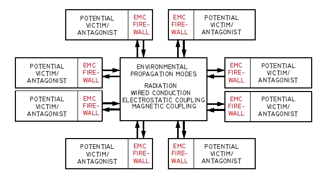
These situations illustrate the value of doing
the homework fo system designers. Here's a
rough illustration that peeks into the risks
for living in the wild and wooly world of
electromagnetic noise.
[img]cid:.0[/img]
In aviation, the diagram can be quite simple . . .
perhaps only three v/a blocks. In a J-3 with no
electrical system, two of the blocks would be
a magneto, the third block might be a hand-held
transceiver. The magnetos would never be victim,
the hand held never antagonistic. But swap out
the mags for electronic ignition systems and they
too are at risk from VHF emissions.
In the Hawker 4000, there were no doubt hundreds
of devices. Each one representing the potential for
being victim, antagonist or both.
The 'fire walls' are critical components of any
design intended to thrive in a hostile/vulnerable
environment. This is what DO-160 testing is all
about. DO-160 is only one of hundreds of qualification
protocols . . . each one tailored to a specific
application.
Just last week I encountered a toe-stubber
in my mini-van. My EMS hand-held listens on 463.750 mHz.
When I got into the car, the receiver squelch opened
up. The hand-held THOUGHT it was hearing our
local EMS repeater. After some switch-flipping and
poking around in the car, I determined that the FM
radio had a spurious output very near the 463.750
frequency of interest. It was present no matter
what mode the radio was in. Turning it completely
off was the only remedy.
In this case, the propagation mode is clearly
radiated and a band-aid remedy is probably more
taxing of time and dollars than to simply replace
the radio. I'll be installing a panel mounted EMS
radio in the car pretty soon . . . the radio will
have to be changed out.
The replacement radio may also offer unfriendly
radiations . . . but likelihood of them being
right on 463.750 are small . . . we shall
see. At least I can test it on the bench before
I put it in the car.
Here's a very well executed video on the functionality
of ferrite beads in the management of hostile
energy . . .
https://youtu.be/81C4IfONt3o
He touches on the use of ferrites on cables
EXTERNAL to a product . . . I've never seen one on
a mouse . . . THAT is a really startling example
of designer malfeasance . . . how hard is it to
put the fire-wall INSIDE the mouse? I've most
often seen cable ferrites on VGA monitor signal
cables. Again, how hard would it be to put the
fire wall inside the monitor? What's to prevent
a user from picking up another cable with the right
connectors with no ferrite bead and suffering
some EM-Incompatibility effect?
In the laboratory environment, one expects the
designers and qualifiers of products to have
test equipment like that in the video to explore
vulnerabilities and spurious emissions . . . and
then add the necessary components to suppress
undesirable effects to acceptable levels. Often,
the effect is not driven down to ZERO . . . it's
just reduced to levels insignificant to reliable
use of the system.
This illustrates the small but real risks for
buying a perfectly good device (like a fuel
pressure transducer) intended for a low-tech
terrestrial application only to find that it
gets fussy when bathed in radio frequency energy
from an aircraft comm radio.
The short answer: It's useful to know which fire-wall
is too short . . . or non-existent. Is it the
transducer, the panel instrument or perhaps
both? Then, is there some error of installation
that compromises the fire wall(s). A common error of
installation is a disconnected shield in the
antenna coax of a transmitter that causes the
feed line to radiate the whole cockpit with RF
energy that exceeds the height of some system's
fire wall.
Fixing the coax shield is easy. But adding height
to or building a new fire-wall into an already
installed system is not so easy.
The ferrite slipped over a wire does what it's
intended to do . . . put an 'impedance lump'
in the conductor. As the video showed us, if
one bead is good, two is better . . . or better
yet, multiple passes through the ferrite is
better still. Inductance goes up as the SQUARE
of turns.
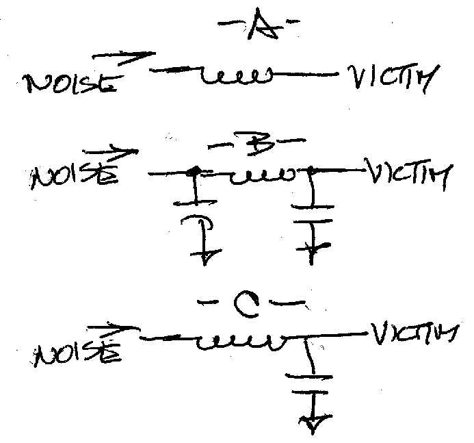
The down side of beads-only attempts to fix
is rooted in the unknown value of a paralleled
SHUNT effect downstream of the SERIES effects.
[img]cid:.1[/img]
In the sketch above, view -A- illustrates the effect
of adding series impedance on a wire where shunt
impedances are at best unknown or worst . . . insignificantly
small. This is often the case where adding the
ferrite 'helps a little'. Ideally, we'd like to see
a combination of series/shunt effects like -C- or
even -B-. The itty-bitty filter I illustrated earlier
[img]cid:.2[/img]
has TWO circuits like -B- above with values
unlikely to upset purely DC signal or power
paths. However, one would not want to put
this device in a USB or serial data line . . .
the components would have deleterious effects
on the desired signals.
The nagging unknown about the case under discussion
is "what changed?" Knowing that answer would
probably provide the short-path to a solution.
Two separate comm systems PLUS a hand-held
will disturb the victim to varying degrees so
a broken coax shield ground can be ruled out.
Given that the affected system was not modified,
then we're encouraged to explore spontaneous
changes within the affected system . . . difficult
to do. Conversely, we're left with the selection
and application of band-aids. From a user's
perspective, a band-aid cure that reduces effects
to zero meets an operational goal. From an
engineer's perspective, not knowing the exact
antagonist->propagation->victim configuration
is frustrating.
As I've mentioned before, I've encountered only
one A>P>V configuration I couldn't fix. Some
were easy, some rather difficult. In the bureaucratic
management of solutions within the world of TC
aircraft, none were very satisfying in that they
often required a band-aid as opposed to a real
fix.
Bob . . .
| | - The Matronics AeroElectric-List Email Forum - | | | Use the List Feature Navigator to browse the many List utilities available such as the Email Subscriptions page, Archive Search & Download, 7-Day Browse, Chat, FAQ, Photoshare, and much more:
http://www.matronics.com/Navigator?AeroElectric-List |
|
| Description: |
|
| Filesize: |
124.87 KB |
| Viewed: |
16778 Time(s) |
|
| Description: |
|
| Filesize: |
99.37 KB |
| Viewed: |
16778 Time(s) |
|
| Description: |
|
| Filesize: |
158.21 KB |
| Viewed: |
16778 Time(s) |

|
|
|
| Back to top |
|
|
jluckey(at)pacbell.net
Guest
|
| Posted: Thu Apr 14, 2016 8:59 am Post subject: RF Interference |
|
|
BobN,
That post is perhaps one of the best primers on EMI I have ever seen.
Short and sweet with block diagrams & schematics - terrific!
Thanks for the continuing education
Jeff Luckey
PS - re your itty-bitty filter:
1. how big is it? perhaps put a penny in the picture
2. when you designed the filter, what frequency are you trying to filter? I'm guessing it's somewhere in 110-140 MHz but what about harmonics?
3. are those tiny surface-mount components an inductor & a cap? (or is it the case that: "you could tell me but then you'd have to kill me?" 
On Thursday, April 14, 2016 9:16 AM, "Robert L. Nuckolls, III" <nuckolls.bob(at)aeroelectric.com> wrote:
At 12:01 AM 4/13/2016, you wrote: | Quote: | | So is there some archive material which expounds on the use of ferrites and the identification of the correct wire / protagonist (as Bob N likes to refer to it!) |
Actually, it's the antagonist . . . but no . . . I'm unaware of any document that leads one through the process of adding ferrites to system wiring in airplanes. These situations illustrate the value of doing the homework fo system designers. Here's a rough illustration that peeks into the risks for living in the wild and wooly world of electromagnetic noise. [img]cid:.0[/img] In aviation, the diagram can be quite simple . . . perhaps only three v/a blocks. In a J-3 with no electrical system, two of the blocks would be a magneto, the third block might be a hand-held transceiver. The magnetos would never be victim, the hand held never antagonistic. But swap out the mags for electronic ignition systems and they too are at risk from VHF emissions. In the Hawker 4000, there were no doubt hundreds of devices. Each one representing the potential for being victim, antagonist or both. The 'fire walls' are critical components of any design intended to thrive in a hostile/vulnerable environment. This is what DO-160 testing is all about. DO-160 is only one of hundreds of qualification protocols . . . each one tailored to a specific application. Just last week I encountered a toe-stubber in my mini-van. My EMS hand-held listens on 463.750 mHz. When I got into the car, the receiver squelch opened up. The hand-held THOUGHT it was hearing our local EMS repeater. After some switch-flipping and poking around in the car, I determined that the FM radio had a spurious output very near the 463.750 frequency of interest. It was present no matter what mode the radio was in. Turning it completely off was the only remedy. In this case, the propagation mode is clearly radiated and a band-aid remedy is probably more taxing of time and dollars than to simply replace the radio. I'll be installing a panel mounted EMS radio in the car pretty soon . . . the radio will have to be changed out. The replacement radio may also offer unfriendly radiations . . . but likelihood of them being right on 463.750 are small . . . we shall see. At least I can test it on the bench before I put it in the car. Here's a very well executed video on the functionality of ferrite beads in the management of hostile energy . . . https://youtu.be/81C4IfONt3o He touches on the use of ferrites on cables EXTERNAL to a product . . . I've never seen one on a mouse . . . THAT is a really startling example of designer malfeasance . . . how hard is it to put the fire-wall INSIDE the mouse? I've most often seen cable ferrites on VGA monitor signal cables. Again, how hard would it be to put the fire wall inside the monitor? What's to prevent a user from picking up another cable with the right connectors with no ferrite bead and suffering some EM-Incompatibility effect? In the laboratory environment, one expects the designers and qualifiers of products to have test equipment like that in the video to explore vulnerabilities and spurious emissions . . . and then add the necessary components to suppress undesirable effects to acceptable levels. Often, the effect is not driven down to ZERO . . . it's just reduced to levels insignificant to reliable use of the system. This illustrates the small but real risks for buying a perfectly good device (like a fuel pressure transducer) intended for a low-tech terrestrial application only to find that it gets fussy when bathed in radio frequency energy from an aircraft comm radio. The short answer: It's useful to know which fire-wall is too short . . . or non-existent. Is it the transducer, the panel instrument or perhaps both? Then, is there some error of installation that compromises the fire wall(s). A common error of installation is a disconnected shield in the antenna coax of a transmitter that causes the feed line to radiate the whole cockpit with RF energy that exceeds the height of some system's fire wall. Fixing the coax shield is easy. But adding height to or building a new fire-wall into an already installed system is not so easy. The ferrite slipped over a wire does what it's intended to do . . . put an 'impedance lump' in the conductor. As the video showed us, if one bead is good, two is better . . . or better yet, multiple passes through the ferrite is better still. Inductance goes up as the SQUARE of turns. The down side of beads-only attempts to fix is rooted in the unknown value of a paralleled SHUNT effect downstream of the SERIES effects. [img]cid:.1[/img] In the sketch above, view -A- illustrates the effect of adding series impedance on a wire where shunt impedances are at best unknown or worst . . . insignificantly small. This is often the case where adding the ferrite 'helps a little'. Ideally, we'd like to see a combination of series/shunt effects like -C- or even -B-. The itty-bitty filter I illustrated earlier [img]cid:.2[/img] has TWO circuits like -B- above with values unlikely to upset purely DC signal or power paths. However, one would not want to put this device in a USB or serial data line . . . the components would have deleterious effects on the desired signals. The nagging unknown about the case under discussion is "what changed?" Knowing that answer would probably provide the short-path to a solution. Two separate comm systems PLUS a hand-held will disturb the victim to varying degrees so a broken coax shield ground can be ruled out. Given that the affected system was not modified, then we're encouraged to explore spontaneous changes within the affected system . . . difficult to do. Conversely, we're left with the selection and application of band-aids. From a user's perspective, a band-aid cure that reduces effects to zero meets an operational goal. From an engineer's perspective, not knowing the exact antagonist->propagation->victim configuration is frustrating. As I've mentioned before, I've encountered only one A>P>V configuration I couldn't fix. Some were easy, some rather difficult. In the bureaucratic management of solutions within the world of TC aircraft, none were very satisfying in that they often required a band-aid as opposed to a real fix. Bob . . .
| | - The Matronics AeroElectric-List Email Forum - | | | Use the List Feature Navigator to browse the many List utilities available such as the Email Subscriptions page, Archive Search & Download, 7-Day Browse, Chat, FAQ, Photoshare, and much more:
http://www.matronics.com/Navigator?AeroElectric-List |
|
| Description: |
|
| Filesize: |
124.87 KB |
| Viewed: |
16777 Time(s) |

|
| Description: |
|
| Filesize: |
99.37 KB |
| Viewed: |
16777 Time(s) |

|
| Description: |
|
| Filesize: |
158.21 KB |
| Viewed: |
16777 Time(s) |
|
|
|
| Back to top |
|
|
ceengland7(at)gmail.com
Guest
|
| Posted: Thu Apr 14, 2016 9:33 am Post subject: RF Interference |
|
|
I've got a question about substituting a battery for the sender's output.
In my (somewhat dim past) experience, the impedance of the line in question had a major effect on its vulnerability to noise induced on it. So.... is this a valid test? I'd assume that the internal impedance of even a AA battery would be much lower than any electronic sensor normally used around an engine.
On 4/14/2016 3:37 AM, B Tomm wrote:
| Quote: | OK,
I have disconnected the output wire at the sender and connected the positive end of an AA battery to the signal wire going off to the engine monitor, and batt neg to ground. I get the appropriate reading for fuel pressure and NO interference from either radio.
This tells me that the interference is happening at the sender. Still not sure if the interference is arriving at the sender via the power or ground wires, or just directly through the air. The instructions say not to connect directly to 12V as this may damage it. So not sure how to test for this.
Still puzzled as to why this happened suddenly.
A new sender has been ordered. BTW, Mouser.com has them for half the price of GRT.
Bob, Do you think that the RF filter you offered is still a valid option? Is it to protect the sender from failing (where the sender becomes sensitive to RF as mine appears to have) or just mitigate the RF from playing games with the senders electronics?
Bevan
From: owner-aeroelectric-list-server(at)matronics.com (owner-aeroelectric-list-server(at)matronics.com) [mailto:owner-aeroelectric-list-server(at)matronics.com (owner-aeroelectric-list-server(at)matronics.com)] On Behalf Of Bob Verwey
Sent: Tuesday, April 12, 2016 10:02 PM
To: aeroelectric-list(at)matronics.com (aeroelectric-list(at)matronics.com)
Subject: Re: RF Interference
So is there some archive material which expounds on the use of ferrites and the identification of the correct wire / protagonist (as Bob N likes to refer to it!)
On 13 April 2016 at 04:22, Chris <toaster73(at)embarqmail.com (toaster73(at)embarqmail.com)> wrote:
| Quote: |
Bevan,
I have an RV-10 with SL30 (archer wingtip antenna), GNS 430 (belly whip), GRT EIS 6000. I experienced the same effect with my fuel pressure. The 430 only bothered the reading a couple of psi, so I decided that was not giving me a problem. The SL30 shot it up out of limits, so I started chasing the problem. I was able to use one ferrite at the sender in the engine compartment with 2 maybe 3 loops (don't recall exactly) of wire going through the ferrite. I also re-crimped the sl30 coax and reaffirmed the archer antenna connections out on the wing. This seems to have solved my problem to only a few psi on the sl30 transmit and virtually none on the 430. I decided I don't talk long enough for the pressure to rise and grab my attention.
-Chris
N919AR
|
--
Best... Bob Verwey
|
| | - The Matronics AeroElectric-List Email Forum - | | | Use the List Feature Navigator to browse the many List utilities available such as the Email Subscriptions page, Archive Search & Download, 7-Day Browse, Chat, FAQ, Photoshare, and much more:
http://www.matronics.com/Navigator?AeroElectric-List |
|
|
|
| Back to top |
|
|
yellowduckduo(at)gmail.co
Guest
|
| Posted: Thu Apr 14, 2016 12:03 pm Post subject: RF Interference |
|
|
I'd guess that the simple battery test confirms it is worth trying the
filter. The filter might actually have even lower impedance to the
frequencies of concern.
FWIW I have a plastic body honeywell SS sensor wired with very small
diameter commercial cable. I don't remember for certain but I think it
is shielded cable. The cable runs in a bundle with injector and primary
ignition wires, past the back of my VHF to an EIS4000. I was curious as
I don't think I've ever watched the pressures while transmitting but I
just confirmed that transmitting has no effect on either of my SS
pressure sensors. FWIW I also run the Byonics APRS and have never
noticed any associated problems with it. I'm delighted with that APRS
transmitter. It is probably the only electronic item in the aircraft
that has run perfectly with no issues at all.
Ken
On 14/04/2016 1:34 PM, Charlie England wrote:
| Quote: | I've got a question about substituting a battery for the sender's output.
In my (somewhat dim past) experience, the impedance of the line in
question had a major effect on its vulnerability to noise induced on
it. So.... is this a valid test? I'd assume that the internal
impedance of even a AA battery would be much lower than any electronic
sensor normally used around an engine.
On 4/14/2016 3:37 AM, B Tomm wrote:
> OK,
> I have disconnected the output wire at the sender and connected
> the positive end of an AA battery to the signal wire going off to the
> engine monitor, and batt neg to ground. I get the appropriate
> reading for fuel pressure and NO interference from either radio.
> This tells me that the interference is happening at the sender.
> Still not sure if the interference is arriving at the sender via the
> power or ground wires, or just directly through the air. The
> instructions say not to connect directly to 12V as this may damage
> it. So not sure how to test for this.
> Still puzzled as to why this happened suddenly.
> A new sender has been ordered. BTW, Mouser.com has them for half the
> price of GRT.
> Bob, Do you think that the RF filter you offered is still a valid
> option? Is it to protect the sender from failing (where the sender
> becomes sensitive to RF as mine appears to have) or just mitigate the
> RF from playing games with the senders electronics?
> Bevan
>
> ------------------------------------------------------------------------
> *From:* owner-aeroelectric-list-server(at)matronics.com
> [mailto:owner-aeroelectric-list-server(at)matronics.com] *On Behalf Of
> *Bob Verwey
> *Sent:* Tuesday, April 12, 2016 10:02 PM
> *To:* aeroelectric-list(at)matronics.com
> *Subject:* Re: RF Interference
>
> So is there some archive material which expounds on the use of
> ferrites and the identification of the correct wire / protagonist (as
> Bob N likes to refer to it!)
>
> On 13 April 2016 at 04:22, Chris <toaster73(at)embarqmail.com
> <mailto:toaster73(at)embarqmail.com>> wrote:
>
> Bevan,
>
> I have an RV-10 with SL30 (archer wingtip antenna), GNS 430
> (belly whip), GRT EIS 6000. I experienced the same effect with my
> fuel pressure. The 430 only bothered the reading a couple of psi,
> so I decided that was not giving me a problem. The SL30 shot it
> up out of limits, so I started chasing the problem. I was able to
> use one ferrite at the sender in the engine compartment with 2
> maybe 3 loops (don't recall exactly) of wire going through the
> ferrite. I also re-crimped the sl30 coax and reaffirmed the
> archer antenna connections out on the wing. This seems to have
> solved my problem to only a few psi on the sl30 transmit and
> virtually none on the 430. I decided I don't talk long enough for
> the pressure to rise and grab my attention.
>
> -Chris
>
> N919AR
>
>
> --
> Best...
> Bob Verwey
>
|
| | - The Matronics AeroElectric-List Email Forum - | | | Use the List Feature Navigator to browse the many List utilities available such as the Email Subscriptions page, Archive Search & Download, 7-Day Browse, Chat, FAQ, Photoshare, and much more:
http://www.matronics.com/Navigator?AeroElectric-List |
|
|
|
| Back to top |
|
|
|
|
You cannot post new topics in this forum
You cannot reply to topics in this forum
You cannot edit your posts in this forum
You cannot delete your posts in this forum
You cannot vote in polls in this forum
You cannot attach files in this forum
You can download files in this forum
|
Powered by phpBB © 2001, 2005 phpBB Group
|

