 |
Matronics Email Lists
Web Forum Interface to the Matronics Email Lists
|
| View previous topic :: View next topic |
| Author |
Message |
art(at)zemon.name
Guest
|
 Posted: Wed Sep 21, 2016 4:37 pm Post subject: Problems Soldering DB-25 Connectors Posted: Wed Sep 21, 2016 4:37 pm Post subject: Problems Soldering DB-25 Connectors |
 |
|
Folks,
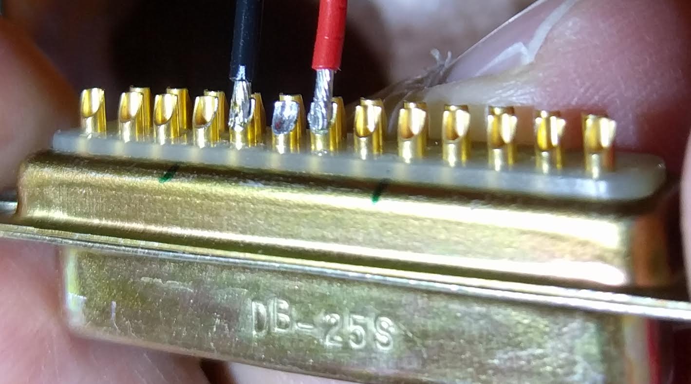
I am trying to solder 20 gauge wire into DB-25 connectors and having a tough time. The conductors just barely fit into the cups on the backs of the pins when everything is "dry," before tinning. After I tin either one, pin or wire, I cannot get all of the conductors into the cup. I end up with something like this:
[img]cid:ii_itdlrj9b0_1574f4d7e91899df[/img]
I'm afraid that those are not acceptable. What do you think?
If they are not acceptable, what is the solution? Can I trim a few conductors away so that the remainder will slip into the cup? Or should I just give up and switch to crimp pins? Or what?
Thanks,
  -- Art Z.
--
http://CheerfulCurmudgeon.com/"If I am not for myself, who is for me? And if I am only for myself, what am I? And if not now, when?" Hillel
| | - The Matronics AeroElectric-List Email Forum - | | | Use the List Feature Navigator to browse the many List utilities available such as the Email Subscriptions page, Archive Search & Download, 7-Day Browse, Chat, FAQ, Photoshare, and much more:
http://www.matronics.com/Navigator?AeroElectric-List |
|
| Description: |
|
| Filesize: |
98.2 KB |
| Viewed: |
20738 Time(s) |
|
|
|
| Back to top |
|
 |
alec(at)alecmyers.com
Guest
|
| Posted: Wed Sep 21, 2016 5:03 pm Post subject: Problems Soldering DB-25 Connectors |
|
|
To me they would be acceptable but there should be some more solder on each pin, so that the solder surface tapers smoothly.
On Sep 21, 2016, at 8:47 PM, Rene <rene(at)felker.com (rene(at)felker.com)> wrote:
| Quote: | v\:* {behavior:url(#default#VML);} o\:* {behavior:url(#default#VML);} w\:* {behavior:url(#default#VML);} .shape {behavior:url(#default#VML);} <![endif]--> <![endif]--> <![endif]-->
I prefer the crimp pins. Easier to create the connector and easier to take it apart or change wires. I have done way more of that then I would have ever imagined when I build the plane.
Rene'
801-721-6080
From: owner-aeroelectric-list-server(at)matronics.com (owner-aeroelectric-list-server(at)matronics.com) [mailto:owner-aeroelectric-list-server(at)matronics.com (owner-aeroelectric-list-server(at)matronics.com)] On Behalf Of Art Zemon
Sent: Wednesday, September 21, 2016 6:34 PM
To: aeroelectric-list(at)matronics.com (aeroelectric-list(at)matronics.com)
Subject: Problems Soldering DB-25 Connectors
Folks,
I am trying to solder 20 gauge wire into DB-25 connectors and having a tough time. The conductors just barely fit into the cups on the backs of the pins when everything is "dry," before tinning. After I tin either one, pin or wire, I cannot get all of the conductors into the cup. I end up with something like this:
<image001.jpg>
I'm afraid that those are not acceptable. What do you think?
If they are not acceptable, what is the solution? Can I trim a few conductors away so that the remainder will slip into the cup? Or should I just give up and switch to crimp pins? Or what?
Thanks,
-- Art Z.
--
http://CheerfulCurmudgeon.com/
"If I am not for myself, who is for me? And if I am only for myself, what am I? And if not now, when?" Hillel
|
| | - The Matronics AeroElectric-List Email Forum - | | | Use the List Feature Navigator to browse the many List utilities available such as the Email Subscriptions page, Archive Search & Download, 7-Day Browse, Chat, FAQ, Photoshare, and much more:
http://www.matronics.com/Navigator?AeroElectric-List |
|
|
|
| Back to top |
|
|
rampil
Joined: 04 May 2007
Posts: 870
|
| Posted: Wed Sep 21, 2016 5:22 pm Post subject: Re: Problems Soldering DB-25 Connectors |
|
|
Be careful about dry joints, the solder should be bright and shiny all around

the joint.  If the wire is carrying just signal, clipping a strand or two should

be fine (with adequate strain relief). Power carrying wire demand more

careful consideration about potential resistive heating and voltage drop.


What I see missing in your picture is heat shrink tubing on each wire

pushed all the down to the connector's insulator block. I'll

assume it is not there just to illustrate the solder joints clearly.
| | - The Matronics AeroElectric-List Email Forum - | | | Use the List Feature Navigator to browse the many List utilities available such as the Email Subscriptions page, Archive Search & Download, 7-Day Browse, Chat, FAQ, Photoshare, and much more:
http://www.matronics.com/Navigator?AeroElectric-List |
|
_________________
Ira N224XS |
|
| Back to top |
|
|
matronics.list(at)gmail.c
Guest
|
| Posted: Wed Sep 21, 2016 5:25 pm Post subject: Problems Soldering DB-25 Connectors |
|
|
Rene'
I also prefer the mil spec crimp pins. But when I solder the connectors I do not tin first. I strip the wire to fit, hold in place and solder in place. It helps to have 4 hands. I will often clamp the connector down and hold the wire in place with one of those alligator clip stands the solder a wire at a time.
or
strip...crimp...insert
John Snapp
+1.303.810.0600
( excuse the typos. This email was sent from a mobile device!)
On Sep 21, 2016, at 5:47 PM, Rene <rene(at)felker.com (rene(at)felker.com)> wrote:
| Quote: | v\:* {behavior:url(#default#VML);} o\:* {behavior:url(#default#VML);} w\:* {behavior:url(#default#VML);} .shape {behavior:url(#default#VML);} <![endif]--> <![endif]--> <![endif]-->
I prefer the crimp pins. Easier to create the connector and easier to take it apart or change wires. I have done way more of that then I would have ever imagined when I build the plane.
Rene'
801-721-6080
From: owner-aeroelectric-list-server(at)matronics.com (owner-aeroelectric-list-server(at)matronics.com) [mailto:owner-aeroelectric-list-server(at)matronics.com (owner-aeroelectric-list-server(at)matronics.com)] On Behalf Of Art Zemon
Sent: Wednesday, September 21, 2016 6:34 PM
To: aeroelectric-list(at)matronics.com (aeroelectric-list(at)matronics.com)
Subject: Problems Soldering DB-25 Connectors
Folks,
I am trying to solder 20 gauge wire into DB-25 connectors and having a tough time. The conductors just barely fit into the cups on the backs of the pins when everything is "dry," before tinning. After I tin either one, pin or wire, I cannot get all of the conductors into the cup. I end up with something like this:
<image001.jpg>
I'm afraid that those are not acceptable. What do you think?
If they are not acceptable, what is the solution? Can I trim a few conductors away so that the remainder will slip into the cup? Or should I just give up and switch to crimp pins? Or what?
Thanks,
-- Art Z.
--
http://CheerfulCurmudgeon.com/
"If I am not for myself, who is for me? And if I am only for myself, what am I? And if not now, when?" Hillel
|
| | - The Matronics AeroElectric-List Email Forum - | | | Use the List Feature Navigator to browse the many List utilities available such as the Email Subscriptions page, Archive Search & Download, 7-Day Browse, Chat, FAQ, Photoshare, and much more:
http://www.matronics.com/Navigator?AeroElectric-List |
|
|
|
| Back to top |
|
|
wgreenley
Joined: 09 Jan 2010
Posts: 100
Location: Dowagiac, MI
|
| Posted: Wed Sep 21, 2016 5:47 pm Post subject: Problems Soldering DB-25 Connectors |
|
|
The solder will wick down into the connection if done right.
On Wed, Sep 21, 2016 at 9:22 PM, john Snapp <matronics.list(at)gmail.com (matronics.list(at)gmail.com)> wrote:
| Quote: | Rene'Â
I also prefer the mil spec crimp pins. But when I solder the connectors I do not tin first. I strip the wire to fit, hold in place and solder in place. It helps to have 4 hands. I will often clamp the connector down and hold the wire in place with one of those alligator clip stands the solder a wire at a time. Â
or Â
strip...crimp....insert
John Snapp
[url=tel:%2B1.303.810.0600]+1.303.810.0600[/url]
( excuse the typos. This email was sent from a mobile device!)
On Sep 21, 2016, at 5:47 PM, Rene <rene(at)felker.com (rene(at)felker.com)> wrote:
| Quote: |
I prefer the crimp pins. Easier to create the connector and easier to take it apart or change wires. I have done way more of that then I would have ever imagined when I build the plane.
Â
Rene'
[url=tel:801-721-6080]801-721-6080[/url]
Â
From: owner-aeroelectric-list-server(at)matronics.com (owner-aeroelectric-list-server(at)matronics.com) [mailto:owner-aeroelectric-list-server(at)matronics.com (owner-aeroelectric-list-server(at)matronics.com)] On Behalf Of Art Zemon
Sent: Wednesday, September 21, 2016 6:34 PM
To: aeroelectric-list(at)matronics.com (aeroelectric-list(at)matronics.com)
Subject: Problems Soldering DB-25 Connectors
Â
Folks,
Â
I am trying to solder 20 gauge wire into DB-25 connectors and having a tough time. The conductors just barely fit into the cups on the backs of the pins when everything is "dry," before tinning. After I tin either one, pin or wire, I cannot get all of the conductors into the cup. I end up with something like this:
Â
<image001.jpg>
I'm afraid that those are not acceptable. What do you think?
Â
If they are not acceptable, what is the solution? Can I trim a few conductors away so that the remainder will slip into the cup? Or should I just give up and switch to crimp pins? Or what?
Â
Thanks,
  -- Art Z.
Â
--
http://CheerfulCurmudgeon.com/
"If I am not for myself, who is for me? And if I am only for myself, what am I? And if not now, when?" Hillel
|
|
| | - The Matronics AeroElectric-List Email Forum - | | | Use the List Feature Navigator to browse the many List utilities available such as the Email Subscriptions page, Archive Search & Download, 7-Day Browse, Chat, FAQ, Photoshare, and much more:
http://www.matronics.com/Navigator?AeroElectric-List |
|
|
|
| Back to top |
|
|
kjashton(at)vnet.net
Guest
|
| Posted: Wed Sep 21, 2016 5:59 pm Post subject: Problems Soldering DB-25 Connectors |
|
|
Do you really need 20 gauge? 22 or even 24 will do for many avionics. If the diagram calls for 20, I'd clip off a few strands. It won't change the wire resistance measurably and if it did, the D-sub acts as a heat sink.
BTW, i would rather solder than fiddle with crimp pins. I tin the cup, tin the wire, then touch the side of the cup with the iron while gently pushing the wire into the cup. It normally slips right in. You must hold your tongue properly, of course. 
-kent
On Sep 21, 2016, at 8:33 PM, Art Zemon <art(at)zemon.name (art(at)zemon.name)> wrote:
| Quote: | Folks,
I am trying to solder 20 gauge wire into DB-25 connectors and having a tough time. The conductors just barely fit into the cups on the backs of the pins when everything is "dry," before tinning. After I tin either one, pin or wire, I cannot get all of the conductors into the cup. I end up with something like this:
<IMG_20160921_192531.jpg>
I'm afraid that those are not acceptable. What do you think?
If they are not acceptable, what is the solution? Can I trim a few conductors away so that the remainder will slip into the cup? Or should I just give up and switch to crimp pins? Or what?
Thanks,
-- Art Z.
--
http://CheerfulCurmudgeon.com/"If I am not for myself, who is for me? And if I am only for myself, what am I? And if not now, when?" Hillel
|
| | - The Matronics AeroElectric-List Email Forum - | | | Use the List Feature Navigator to browse the many List utilities available such as the Email Subscriptions page, Archive Search & Download, 7-Day Browse, Chat, FAQ, Photoshare, and much more:
http://www.matronics.com/Navigator?AeroElectric-List |
|
|
|
| Back to top |
|
|
stein(at)steinair.com
Guest
|
| Posted: Wed Sep 21, 2016 7:00 pm Post subject: Problems Soldering DB-25 Connectors |
|
|
YES
On Wednesday, September 21, 2016, Charlie England <ceengland7(at)gmail.com (ceengland7(at)gmail.com)> wrote:
| Quote: | On 9/21/2016 7:33 PM, Art Zemon wrote:
| Quote: | Folks......
Or should I just give up and switch to crimp pins? Or what?
Thanks,
  -- Art Z.
--
http://CheerfulCurmudgeon.com/ "If I am not for myself, who is for me? And if I am only for myself, what am I? And if not now, when?" Hillel
|
|
| | - The Matronics AeroElectric-List Email Forum - | | | Use the List Feature Navigator to browse the many List utilities available such as the Email Subscriptions page, Archive Search & Download, 7-Day Browse, Chat, FAQ, Photoshare, and much more:
http://www.matronics.com/Navigator?AeroElectric-List |
|
|
|
| Back to top |
|
|
cluros(at)gmail.com
Guest
|
| Posted: Thu Sep 22, 2016 1:21 am Post subject: Problems Soldering DB-25 Connectors |
|
|
You and everyone else who hasn't spent a lot of time practicing soldering them. Two choices. Keep trying until you get it right or my favorite:
Get rid of the solder connectors and order some crimp ones.
Sebastien
On Sep 21, 2016, at 20:33, Art Zemon <art(at)zemon.name (art(at)zemon.name)> wrote:
| Quote: | Folks,
I am trying to solder 20 gauge wire into DB-25 connectors and having a tough time. The conductors just barely fit into the cups on the backs of the pins when everything is "dry," before tinning. After I tin either one, pin or wire, I cannot get all of the conductors into the cup. I end up with something like this:
<IMG_20160921_192531.jpg>
I'm afraid that those are not acceptable. What do you think?
If they are not acceptable, what is the solution? Can I trim a few conductors away so that the remainder will slip into the cup? Or should I just give up and switch to crimp pins? Or what?
Thanks,
-- Art Z.
--
http://CheerfulCurmudgeon.com/"If I am not for myself, who is for me? And if I am only for myself, what am I? And if not now, when?" Hillel
|
| | - The Matronics AeroElectric-List Email Forum - | | | Use the List Feature Navigator to browse the many List utilities available such as the Email Subscriptions page, Archive Search & Download, 7-Day Browse, Chat, FAQ, Photoshare, and much more:
http://www.matronics.com/Navigator?AeroElectric-List |
|
| Description: |
|
| Filesize: |
98.2 KB |
| Viewed: |
20723 Time(s) |

|
|
|
| Back to top |
|
|
racerjerry
Joined: 15 Dec 2009
Posts: 202
Location: Deer Park, NY
|
| Posted: Thu Sep 22, 2016 4:25 am Post subject: Re: Problems Soldering DB-25 Connectors |
|
|
To tin the wire, I first clamp the stripped wire into my padded vise. After applying solder, I immediately wipe the tinned end to remove any excess solder. I use an old washcloth. Reapply heat, pinch the rag between thumb and finger around the wire and pull straight off the conductor. This should result in no stray strands and minimum solder.
| | - The Matronics AeroElectric-List Email Forum - | | | Use the List Feature Navigator to browse the many List utilities available such as the Email Subscriptions page, Archive Search & Download, 7-Day Browse, Chat, FAQ, Photoshare, and much more:
http://www.matronics.com/Navigator?AeroElectric-List |
|
_________________
Jerry King |
|
| Back to top |
|
|
nuckolls.bob(at)aeroelect
Guest
|
| Posted: Thu Sep 22, 2016 5:50 am Post subject: Problems Soldering DB-25 Connectors |
|
|
At 07:33 PM 9/21/2016, you wrote:
| Quote: | Folks,
I am trying to solder 20 gauge wire into DB-25 connectors and having a tough time. The conductors just barely fit into the cups on the backs of the pins when everything is "dry," before tinning. After I tin either one, pin or wire, I cannot get all of the conductors into the cup. I end up with something like this: |
Then don't 'tin' them first. In my Shop Note for dealing
with solder-cup d-subs, I suggest tinning before dropping
it into pre-filled cups. With 22AWG, the fits are not so
tight and the process works well. When the stranding is
tight, as with 20AWG, it's better to dry fit then solder.
Bob . . .
| | - The Matronics AeroElectric-List Email Forum - | | | Use the List Feature Navigator to browse the many List utilities available such as the Email Subscriptions page, Archive Search & Download, 7-Day Browse, Chat, FAQ, Photoshare, and much more:
http://www.matronics.com/Navigator?AeroElectric-List |
|
|
|
| Back to top |
|
|
nuckolls.bob(at)aeroelect
Guest
|
| Posted: Thu Sep 22, 2016 6:04 am Post subject: Problems Soldering DB-25 Connectors |
|
|
At 08:22 PM 9/21/2016, you wrote:
| Quote: | --> AeroElectric-List message posted by: "rampil" <ira.rampil(at)gmail.com>
Be careful about dry joints, the solder should be bright and shiny all around
the joint. |
. . . which is easy to achieve with 63/37 solder featuring
quality flux.
| Quote: | If the wire is carrying just signal, clipping a strand or two should
be fine . . . |
I've attached 18 AWG wires to solder-cups by trimming
back excess strands. This was a system with long runs
of wire where voltage drop was an issue. There are
companies that make special adapters to put too-large
wires into 20AWG solder-cups but trimming the strands
is more compact and works good too.
| Quote: | | (with adequate strain relief). |
The backshell is were wire-support takes place.
Heat shrink is more of a hedge against pin-to-pin
shorts by conductive contaminants . . . a thing
that just doesn't happen in a clean work environment.
| Quote: | Power carrying wire demand more careful consideration
about potential resistive heating and voltage drop. |
Sort of . . . but pin-to-socket interface within
the connector is the driving concern about path
resistance. 20AWG wire is 10 milliohms per FOOT,
22AWG is 16 mOhms/Ft. A single pin-to-socket
interface on a d-sub can present 3 millioms of
resistance over a millimeter. Variability in
resistance between pin-to-socket interface within
a connector gives rise to the prohibition for
paralleling pins to increase current handling
of any one path.
I designed and qualified a paralleled d-sub pin
process at Beech that was used in both targets
and production aircraft. This involved EXTENDING
each pin in a paralleled array with say 12" of
22AWG wire before the pin-paths were joined in
parallel. This ADDS 16 milliohms resistance to
each 1-3 milliohm pin-to-socket variability.
This 'ballasting' resistance forces the sharing
of current across an array of paralleled pins.
The short answer is that concerns for heating
due to current flow reside in the pins . . .
not the wires.
Bob . . .
| | - The Matronics AeroElectric-List Email Forum - | | | Use the List Feature Navigator to browse the many List utilities available such as the Email Subscriptions page, Archive Search & Download, 7-Day Browse, Chat, FAQ, Photoshare, and much more:
http://www.matronics.com/Navigator?AeroElectric-List |
|
|
|
| Back to top |
|
|
nuckolls.bob(at)aeroelect
Guest
|
| Posted: Thu Sep 22, 2016 7:06 am Post subject: Problems Soldering DB-25 Connectors |
|
|
At 07:33 PM 9/21/2016, you wrote:
| Quote: | Folks,
I am trying to solder 20 gauge wire into DB-25 connectors and having a tough time. The conductors just barely fit into the cups on the backs of the pins when everything is "dry," before tinning. After I tin either one, pin or wire, I cannot get all of the conductors into the cup. I end up with something like this: |
Art, if you do not have 63/37 solder of known
pedigree, drop me your mailing address and
I'll send you enough to do a handful of d-dsub
jobs . . . having a good solder is 75% of the
task, good iron is 20% thus making your probability
of success in mastering the last 5% more of
a sure thing.
Bob . . .
| | - The Matronics AeroElectric-List Email Forum - | | | Use the List Feature Navigator to browse the many List utilities available such as the Email Subscriptions page, Archive Search & Download, 7-Day Browse, Chat, FAQ, Photoshare, and much more:
http://www.matronics.com/Navigator?AeroElectric-List |
|
|
|
| Back to top |
|
|
art(at)zemon.name
Guest
|
| Posted: Fri Sep 23, 2016 4:24 am Post subject: Problems Soldering DB-25 Connectors |
|
|
Folks,

Thank you for all of your advice. Last night, I did some more experimenting and achieved much better results. My solder-sucker doesn't completely clean out the old solder from the cups so I will try some solder wick tomorrow (no time tonight). I got most of the solder out, trimmed a few conductors from the wire, and was able to neatly and securing solder 20 AWG wires to pins. It was quick and I have connections that look safe and secure.

In case you are curious, unless the solder wick works miracles, I will discard the DB-25 connectors that I have "messed up" and start from scratch. I am not driven by any irrational need to salvage these things. What I thought would be a simple assembly process has turned into a great learning exercise.

I'll let you know how things go later this weekend.

Cheers,

    -- Art Z.

--

http://CheerfulCurmudgeon.com/"If I am not for myself, who is for me? And if I am only for myself, what am I? And if not now, when?" Hillel
| | - The Matronics AeroElectric-List Email Forum - | | | Use the List Feature Navigator to browse the many List utilities available such as the Email Subscriptions page, Archive Search & Download, 7-Day Browse, Chat, FAQ, Photoshare, and much more:
http://www.matronics.com/Navigator?AeroElectric-List |
|
|
|
| Back to top |
|
|
efraim.otero(at)gmail.com
Guest
|
| Posted: Fri Sep 23, 2016 6:36 am Post subject: Problems Soldering DB-25 Connectors |
|
|
Art:Please send pictures so us newbies can compare⦠thanks for sharing!!
E | Quote: | On Sep 23, 2016, at 7:22 AM, Art Zemon <art(at)zemon.name (art(at)zemon.name)> wrote:
Folks,
Thank you for all of your advice. Last night, I did some more experimenting and achieved much better results. My solder-sucker doesn't completely clean out the old solder from the cups so I will try some solder wick tomorrow (no time tonight). I got most of the solder out, trimmed a few conductors from the wire, and was able to neatly and securing solder 20 AWG wires to pins. It was quick and I have connections that look safe and secure.
In case you are curious, unless the solder wick works miracles, I will discard the DB-25 connectors that I have "messed up" and start from scratch. I am not driven by any irrational need to salvage these things. What I thought would be a simple assembly process has turned into a great learning exercise.
I'll let you know how things go later this weekend.
Cheers,
-- Art Z.
-- http://CheerfulCurmudgeon.com/"If I am not for myself, who is for me? And if I am only for myself, what am I? And if not now, when?" Hillel
|
| | - The Matronics AeroElectric-List Email Forum - | | | Use the List Feature Navigator to browse the many List utilities available such as the Email Subscriptions page, Archive Search & Download, 7-Day Browse, Chat, FAQ, Photoshare, and much more:
http://www.matronics.com/Navigator?AeroElectric-List |
|
|
|
| Back to top |
|
|
nuckolls.bob(at)aeroelect
Guest
|
| Posted: Fri Sep 23, 2016 10:34 am Post subject: Problems Soldering DB-25 Connectors |
|
|
At 07:22 AM 9/23/2016, you wrote:
| Quote: | Folks,
Thank you for all of your advice. Last night, I did some more experimenting and achieved much better results. |
Yes . . . the learning curve is rather
steep but it DOES take some practice . . .
| Quote: | | My solder-sucker doesn't completely clean out the old solder from the cups so I will try some solder wick tomorrow (no time tonight). |
I have solder-sukers . . . VERY SELDOM used
except to open a plated through hole in a
circuit board. Really most effective when
powered by vacuum pump pulling on a heated
tip attached to the end of a soldering iron.
| Quote: | | I got most of the solder out, trimmed a few conductors from the wire, and was able to neatly and securing solder 20 AWG wires to pins. It was quick and I have connections that look safe and secure. |
Good for you. Solder wick can be VERY effective
but there are some pot-holes. The wicking needs
to be FINE and impregnated with a good dry flus.
There are many good ones and many more poor ones.
| Quote: | | In case you are curious, unless the solder wick works miracles, I will discard the DB-25 connectors that I have "messed up" and start from scratch. I am not driven by any irrational need to salvage these things. |
Try heating a solder cup then rapping the
connector on the workbench to shake out the
molten solder. I would hold the connector in
a pair of pliers by the end-tab, heat the
solder cup then 'whack' the piers on the
bench with solder cup facing down. You'll
find it is quite clean.
| Quote: | | What I thought would be a simple assembly process has turned into a great learning exercise. |
My 'lifetime supply' of Chemtronics wick is holding
up well so I'm out of school on current
offerings. I'll order some samples of current offerings
on 'solder wick' off eBay. It's a whole new bunch of
players since I ordered any.
Bob . . .
| | - The Matronics AeroElectric-List Email Forum - | | | Use the List Feature Navigator to browse the many List utilities available such as the Email Subscriptions page, Archive Search & Download, 7-Day Browse, Chat, FAQ, Photoshare, and much more:
http://www.matronics.com/Navigator?AeroElectric-List |
|
|
|
| Back to top |
|
|
art(at)zemon.name
Guest
|
| Posted: Sat Sep 24, 2016 11:49 am Post subject: Problems Soldering DB-25 Connectors |
|
|
On Fri, Sep 23, 2016 at 9:29 AM, Efraim Otero <efraim.otero(at)gmail.com (efraim.otero(at)gmail.com)> wrote:
| Quote: | Art:Please send pictures so us newbies can compare⦠thanks for sharing!!
|
Efraim,
Your wish is my command
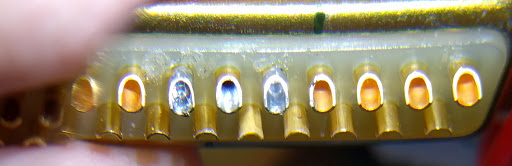
Desoldering went well. Bob's suggestion to melt the solder and then wack the pliers-holding-the-connector on the workbench did the trick much better than the solder wick. I ended up with nice clean cups like this:
[img]cid:ii_ithli9ql0_1575db16d60d4473[/img]
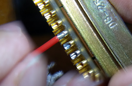
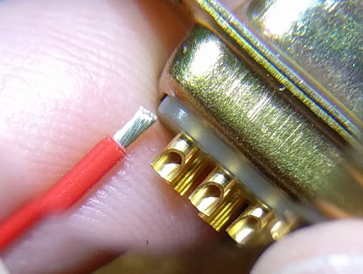
I stripped the wire to the length that would fit into the pin. Here is a photo showing the scale (I am not going to solder this wire into the pin on the end).
[img]cid:ii_ithljh8h1_1575db248f2d8d0a[/img]
I set the wire into the pin and it stayed nicely in position all by itself, making the soldering super easy.Â
[img]cid:ii_ithlp7ok4_1575db6612438769[/img]
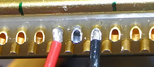
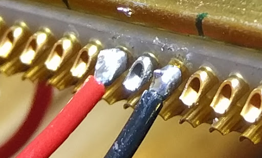
Here is a photo with the red wire already soldered and the black wire set in place, ready to be soldered.
[img]cid:ii_ithlmbyv2_1575db453e7b7502[/img]
With both soldered, I have connections that please me very much. They are mechanically solid, which gives me confidence that these will last the life of my airplane. (They actually look better in real life than in this photo, which has some terrible reflections.)
[img]cid:ii_ithlos7l3_1575db61140ca845[/img]
Reinforcing my confidence in these connections, they were very quick. Since the wire set neatly and securely into the cups, total time to strip the wire, set it into the cup, and apply solder was well under 60 seconds. Previously, I had been fighting the wire and fighting with clamps to get everything to stay in position so that I could solder; it was taking me 5-10 minutes per pin with lots of do-overs.
Hat tip again to all of you who helped me. Thank you!
  -- Art Z.
[img]https://render.bitstrips.com/v2/cpanel/10117671-152852629_2-s1-v1.png?transparent=1[/img]
--
http://CheerfulCurmudgeon.com/"If I am not for myself, who is for me? And if I am only for myself, what am I? And if not now, when?" Hillel
| | - The Matronics AeroElectric-List Email Forum - | | | Use the List Feature Navigator to browse the many List utilities available such as the Email Subscriptions page, Archive Search & Download, 7-Day Browse, Chat, FAQ, Photoshare, and much more:
http://www.matronics.com/Navigator?AeroElectric-List |
|
| Description: |
|
| Filesize: |
59.42 KB |
| Viewed: |
20676 Time(s) |
|
| Description: |
|
| Filesize: |
45.21 KB |
| Viewed: |
20676 Time(s) |

|
| Description: |
|
| Filesize: |
39.85 KB |
| Viewed: |
20676 Time(s) |
|
| Description: |
|
| Filesize: |
33.7 KB |
| Viewed: |
20676 Time(s) |
|
| Description: |
|
| Filesize: |
61.64 KB |
| Viewed: |
20676 Time(s) |
|
|
|
| Back to top |
|
|
art(at)zemon.name
Guest
|
| Posted: Sat Sep 24, 2016 2:47 pm Post subject: Problems Soldering DB-25 Connectors |
|
|
On Sat, Sep 24, 2016 at 2:46 PM, Art Zemon <art(at)zemon.name (art(at)zemon.name)> wrote:
| Quote: | On Fri, Sep 23, 2016 at 9:29 AM, Efraim Otero <efraim.otero(at)gmail.com (efraim.otero(at)gmail.com)> wrote:
| Quote: | Art:Please send pictures so us newbies can compare⦠thanks for sharing!!
|
Efraim,
Your wish is my command
|
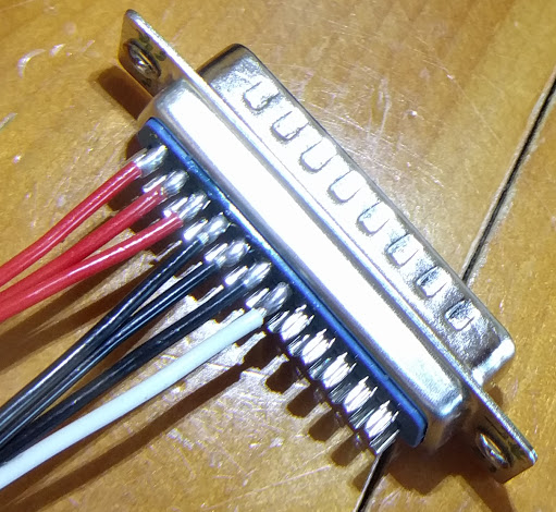
One more photo. I disassembled and reassembled the first connector that I did (more than a week ago). I am much happier with this iteration:
[img]cid:ii_iths7mqz0_1575e5d42f606419[/img]
These wires are for the pitot tube heater. It draws 12 amps so I am using three pins each for power, plus one pin for the status lamp. These three 20 AWG pigtails join to 12 AWG wire which runs the length of the wing.
Cheers,
  -- Art Z.
--
http://CheerfulCurmudgeon.com/"If I am not for myself, who is for me? And if I am only for myself, what am I? And if not now, when?" Hillel
| | - The Matronics AeroElectric-List Email Forum - | | | Use the List Feature Navigator to browse the many List utilities available such as the Email Subscriptions page, Archive Search & Download, 7-Day Browse, Chat, FAQ, Photoshare, and much more:
http://www.matronics.com/Navigator?AeroElectric-List |
|
| Description: |
|
| Filesize: |
102.27 KB |
| Viewed: |
20673 Time(s) |
|
|
|
| Back to top |
|
|
nuckolls.bob(at)aeroelect
Guest
|
| Posted: Sun Sep 25, 2016 12:47 am Post subject: Problems Soldering DB-25 Connectors |
|
|
| Quote: |
[img]cid:7.1.0.9.0.20160925033820.04fee7b8(at)aeroelectric.com.5[/img]
Reinforcing my confidence in these connections, they were very quick. Since the wire set neatly and securely into the cups, total time to strip the wire, set it into the cup, and apply solder was well under 60 seconds. Previously, I had been fighting the wire and fighting with clamps to get everything to stay in position so that I could solder; it was taking me 5-10 minutes per pin with lots of do-overs.
Hat tip again to all of you who helped me. Thank you!
|
You're gaining on it! My only impression now is that
I would strive for better wetting/flow in the
finished joints. Your iron temp may to too low.
It could be a solder issue too. You said 60/40 . . .
normally that alloy is quite satisfactory. Used it
the first few decades of my solder slinging career.
But I've had some 63/37 of some brands that did
not behave optimally. What brand of solder are you
using?
I'll send you some solder Monday. What kind of
iron are you using?
Bob . . .
| | - The Matronics AeroElectric-List Email Forum - | | | Use the List Feature Navigator to browse the many List utilities available such as the Email Subscriptions page, Archive Search & Download, 7-Day Browse, Chat, FAQ, Photoshare, and much more:
http://www.matronics.com/Navigator?AeroElectric-List |
|
| Description: |
|
| Filesize: |
45.21 KB |
| Viewed: |
20653 Time(s) |
|
|
|
| Back to top |
|
|
nuckolls.bob(at)aeroelect
Guest
|
| Posted: Sun Sep 25, 2016 1:10 am Post subject: Problems Soldering DB-25 Connectors |
|
|
At 05:44 PM 9/24/2016, you wrote:
| Quote: | On Sat, Sep 24, 2016 at 2:46 PM, Art Zemon <art(at)zemon.name (art(at)zemon.name)> wrote:
On Fri, Sep 23, 2016 at 9:29 AM, Efraim Otero <efraim.otero(at)gmail.com (efraim.otero(at)gmail.com) > wrote:
Art:
Please send pictures so us newbies can compare
thanks for sharing!!
Efraim,
Your wish is my command
One more photo. I disassembled and reassembled the first connector that I did (more than a week ago). I am much happier with this iteration:
[img]cid:.0[/img]
These wires are for the pitot tube heater. It draws 12 amps so I am using three pins each for power, plus one pin for the status lamp. These three 20 AWG pigtails join to 12 AWG wire which runs the length of the wing. |
These joints look good. I would use 22AWG "ballast
resistor" pigtails. Here you are actually using
the wire as a resistor . . . the larger the better
from the standpoint of sharing loads across an
array of pins. Also, be aware that the legacy
heated pitot tubes have a strong temperature
coefficient. A typical pitot heater for a Beechejt
is 1.5 ohms at 0C . . . a time when the tube is
likely to be turned on. 28V/1.5 ohms is 18A start
up current. When the heater gets to 100C (typical
high altitude condition) it goes to 2.2 ohms
for 12.7A running current. 14v probes behave similarly
at about 2x the current.
What kind of probe are we talking about?
If you've lots of unused pins in this connector,
it wouldn't hurt to use 5 or 6 pins per path
and I'd certainly drop to 22AWG ballast wires.
Another thing to consider for the solder-cup
connector is the form of the female pins in
the connector . . . not quite as robust and
uniform their crimp style cousins . . . so
extra pins if available wouldn't hurt a thing.
The work we did at Beech was entirely with
crimped pins. I'm not suggesting that your
design goals cannot be met with this connector,
just that I have no experience with the parallel
pins in the commercial connectors so if there
are unused pins in the connector, bringing
them into harness with the three already in
service is not a bad thing to consider.
The extra wire is a 'sense' wire? What does
it do for you?
Bob . . .
| | - The Matronics AeroElectric-List Email Forum - | | | Use the List Feature Navigator to browse the many List utilities available such as the Email Subscriptions page, Archive Search & Download, 7-Day Browse, Chat, FAQ, Photoshare, and much more:
http://www.matronics.com/Navigator?AeroElectric-List |
|
| Description: |
|
| Filesize: |
216.87 KB |
| Viewed: |
20653 Time(s) |

|
|
|
| Back to top |
|
|
art(at)zemon.name
Guest
|
| Posted: Sun Sep 25, 2016 5:20 am Post subject: Problems Soldering DB-25 Connectors |
|
|
On Sun, Sep 25, 2016 at 3:43 AM, Robert L. Nuckolls, III <nuckolls.bob(at)aeroelectric.com (nuckolls.bob(at)aeroelectric.com)> wrote:
| Quote: | | Quote: |
[img]cid:7.1.0.9.0.20160925033820.04fee7b8(at)aeroelectric.com.5[/img]
Reinforcing my confidence in these connections, they were very quick. Since the wire set neatly and securely into the cups, total time to strip the wire, set it into the cup, and apply solder was well under 60 seconds. Previously, I had been fighting the wire and fighting with clamps to get everything to stay in position so that I could solder; it was taking me 5-10 minutes per pin with lots of do-overs.
Hat tip again to all of you who helped me. Thank you!
|
 You're gaining on it! My only impression now is that
 I would strive for better wetting/flow in the
 finished joints. Your iron temp may to too low.
 It could be a solder issue too. You said 60/40 . . .
 normally that alloy is quite satisfactory. Used it
 the first few decades of my solder slinging career.
 But I've had some 63/37 of some brands that did
 not behave optimally. What brand of solder are you
 using?
 I'll send you some solder Monday. What kind of
 iron are you using?
|
Bob,
I am using a Weller WES51. I have been setting it at 650 when butt splicing wires and bumped up to 700 degrees for the DB-25 pins. I can certainly try something hotter. I was worried about damaging the connector.Â
I have two tips for the iron, the one that came with it and an extra narrow tip that I also bought. I find that extra narrow tip easier to control when working on the DB-25 pins but it doesn't transfer heat as well.
I am using Kester 60/40 solder.Â
Cheers,
  -- Art Z.
--
http://CheerfulCurmudgeon.com/"If I am not for myself, who is for me? And if I am only for myself, what am I? And if not now, when?" Hillel
| | - The Matronics AeroElectric-List Email Forum - | | | Use the List Feature Navigator to browse the many List utilities available such as the Email Subscriptions page, Archive Search & Download, 7-Day Browse, Chat, FAQ, Photoshare, and much more:
http://www.matronics.com/Navigator?AeroElectric-List |
|
| Description: |
|
| Filesize: |
45.21 KB |
| Viewed: |
20649 Time(s) |

|
|
|
| Back to top |
|
|
|
|
You cannot post new topics in this forum
You cannot reply to topics in this forum
You cannot edit your posts in this forum
You cannot delete your posts in this forum
You cannot vote in polls in this forum
You cannot attach files in this forum
You can download files in this forum
|
Powered by phpBB © 2001, 2005 phpBB Group
|

