 |
Matronics Email Lists
Web Forum Interface to the Matronics Email Lists
|
| View previous topic :: View next topic |
| Author |
Message |
user9253
Joined: 28 Mar 2008
Posts: 1967
Location: Riley TWP Michigan
|
 Posted: Sun Jan 22, 2017 5:08 pm Post subject: Re: Starter Contactors Posted: Sun Jan 22, 2017 5:08 pm Post subject: Re: Starter Contactors |
 |
|
Yes, induced current will only flow through the arc suppression diode. No induced current will flow through the LED because the LED will be reversed biased. The arrows on the arc suppression diode and the LED point in opposite directions. The value of the resistor is irrelevant because any induced voltage has the wrong polarity to illuminate the LED.
| Quote: | | Will the disconnect surge still flow via the diode rather than the LED if the LED resistance is sufficient? |
| | - The Matronics AeroElectric-List Email Forum - | | | Use the List Feature Navigator to browse the many List utilities available such as the Email Subscriptions page, Archive Search & Download, 7-Day Browse, Chat, FAQ, Photoshare, and much more:
http://www.matronics.com/Navigator?AeroElectric-List |
|
_________________
Joe Gores |
|
| Back to top |
|
 |
nuckolls.bob(at)aeroelect
Guest
|
| Posted: Mon Jan 23, 2017 4:39 am Post subject: Starter Contactors |
|
|
At 07:42 AM 1/21/2017, you wrote:
| Quote: | --> AeroElectric-List message posted by: C&K <yellowduckduo(at)gmail.com>
Many marine and aftermarket key switches have a substantial rating such as 25 Amps on the package which has mislead me in the past. That rating is often the total contact rating. ie 5 for starter, 10 for ignition, and 10 for accessories.
Nevertheless in my case the starting contacts are still working fine after several thousand starts wired directly to the solenoid and with the recommended diode. My subaru starter solenoid has two windings so that the pull in current is quite high (more than 30 amps) but then after pull in, only the second winding flows current (about 9 amps) .
Ken |
The only time I personally observed severe
effects of compound wound solenoids on
key-switch contacts was in the parking lot
of Vidimation, Inc. where I was manager. One
of my techs had a Pacific Rim vehicle
that wouldn't crank. We dug into the
steering column and upon exposing the
keyswitch, the electrical assembly
behind the cylinder came out in pieces
with evidence of overheat damage . . .
centered on contacts that energized
the starter.
It wasn't until years later, working with
starter upgrades to OBAM aircraft at B&C
that I was introduced to the unique energization
characteristics of the compound-wound engagement
solenoids.
It was then that I hypothesized a connection
between solenoid configurations and switch
damage observed on the car.
In that same time frame, the effects inductive
energy storage on slow-make/slow-break
switch contacts bubbled up in the TC aircraft
world. The FAA published their infamous AD
against the classic aviation key switches
marketed by first by Gerdes and later by Aircraft
Spruce.
Seems there was a rise in frequency of
failure in the starter control contacts
diagnosed as a combination of poor lubrication
and inductive energy dissipation.
See http://tinyurl.com/go9a4g8
The initial fix was to install
a diode across the contacts of the switch.
The AD was published no doubt causing
numerous installations of diodes in the
wrong place. It's interesting that the
service difficulties first presented for
controlling ordinary contactors . . . attempting
to control a compound-wound, engagement
solenoid through these same contacts would
have been problematic at best.
I was working the STC kit for installation
of B&C starters at the time. Our kit
included a new, separate, high-current,
snap-action push-button which was better
suited to the task of controlling
the intermittent duty contactors. Further,
we elected to ADD the external, intermittent
duty contactor to the starter control circuit.
That was when I first incorporated low voltage
MOV devices as enhancements to switch life.
I made the decision based on interpretation
of catalog data without bench verification.
Some years later, the question was raised on
one of the list servers. I went to the
bench and was disappointed to discover that
the decision was poorly founded and I began
to eliminate the MOV from the z-figures.
Unfortunately, that transition of ideas did
not filter down to the community that had
already fabricated to the earlier drawings.
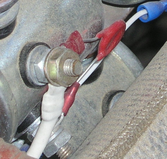
Found this MOV installation during the investigation
into root cause of an aircraft accident (The MOV
was not involved).
[img]cid:7.1.0.9.0.20170122084825.006dc3c8(at)aeroelectric.com.0[/img]
Fortunately this mis-application contributes to nothing
worse than poor service life on the controlling switch
and in this case (whisky-barrel contactor) to an
insignificant degree. The MOV is not being used to
stand off the 'lightning bolts' from a lightweight
starter solenoid.
Cessna first put diodes on battery contactors and
altenrator control relays while I worked there (1864-69).
Looking through wiring diagrams I have for that era shows
no diodes on starter contactors. Seems it took about 20
years for difficulties for that ommission to bubble to
the surface.
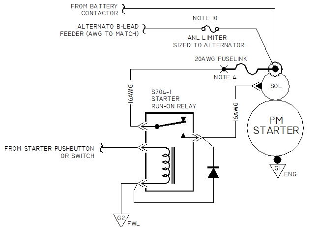
Bottom line tells us that simple diode suppression
of energy stored on contactor or solenoid inductance
is a GOOD thing. Buffering compound-wound starter
solenoid controls with a relay is probably another
GOOD thing.
[img]cid:7.1.0.9.0.20170122084825.006dc3c8(at)aeroelectric.com.1[/img]
Bob . . .
| | - The Matronics AeroElectric-List Email Forum - | | | Use the List Feature Navigator to browse the many List utilities available such as the Email Subscriptions page, Archive Search & Download, 7-Day Browse, Chat, FAQ, Photoshare, and much more:
http://www.matronics.com/Navigator?AeroElectric-List |
|
| Description: |
|
| Filesize: |
251.73 KB |
| Viewed: |
2607 Time(s) |
|
| Description: |
|
| Filesize: |
87.6 KB |
| Viewed: |
2607 Time(s) |
|
|
|
| Back to top |
|
|
|
|
You cannot post new topics in this forum
You cannot reply to topics in this forum
You cannot edit your posts in this forum
You cannot delete your posts in this forum
You cannot vote in polls in this forum
You cannot attach files in this forum
You can download files in this forum
|
Powered by phpBB © 2001, 2005 phpBB Group
|

