 |
Matronics Email Lists
Web Forum Interface to the Matronics Email Lists
|
| View previous topic :: View next topic |
| Author |
Message |
supik
Joined: 22 Aug 2018
Posts: 70
|
 Posted: Sun Jan 13, 2019 3:29 am Post subject: Basic Elec. Diagram -critique pls Posted: Sun Jan 13, 2019 3:29 am Post subject: Basic Elec. Diagram -critique pls |
 |
|
(I have posted this on VAF as well)
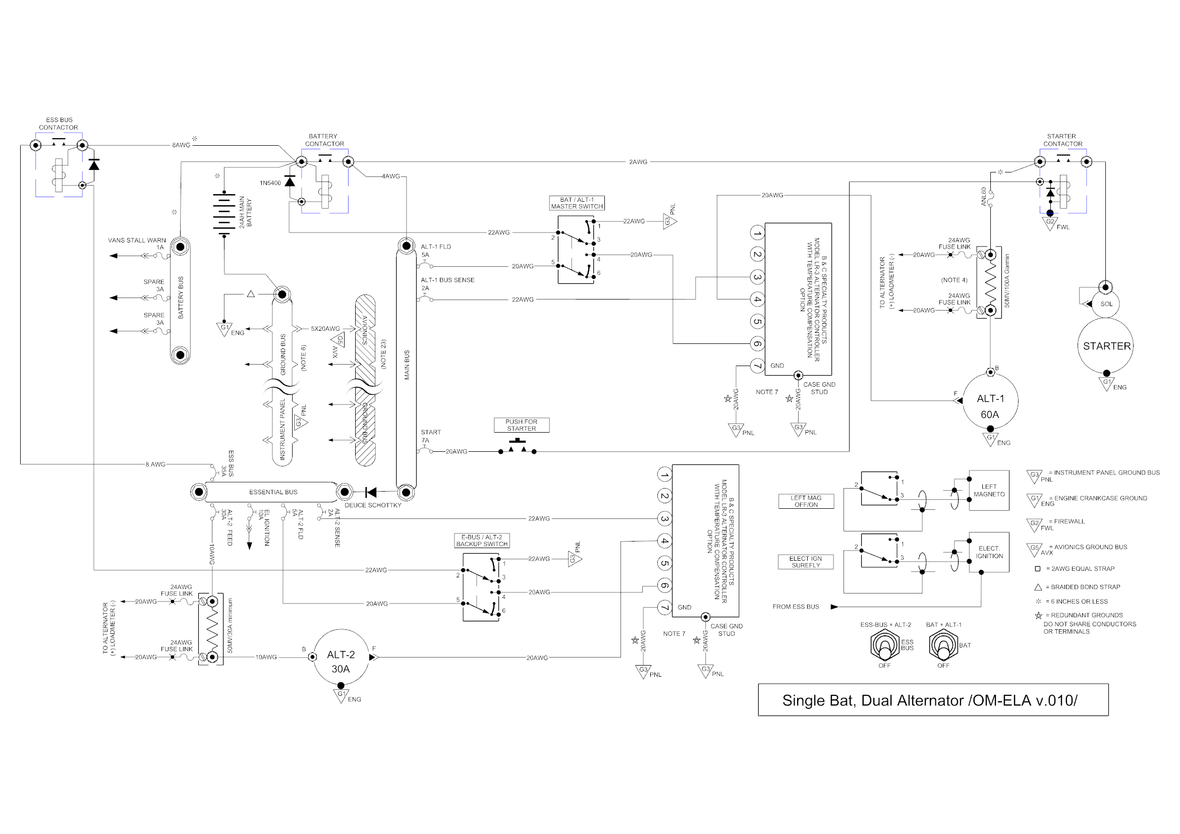
This is my preliminary diagram for my RV-10
Single battery, dual alternator setup. (60amp B&C + 30amp B&C)
Backup & Master switches ON during normal ops.
Both alternators will be ON during normal ops.
ALT-1 (60amp) regulator preset at 14.4V
ALT-2 (30amp) regulator preset at 13.8V
Both regulators are LR3C-14
LV lights from regulators NOT utilized. Respective BUS voltages monitored by G3X Touch.
-MAIN BUS threshold monitoring at or below 13.8V triggers (MASTER CAUT) MAIN BUS LV
-ESS BUS threshold monitoring at or below 13.0V triggers (MASTER WARN) ESS BUS LV
I hope this is possible to setup with the G3X Touch, expert opinion is welcomed.
Shall the ESS-BUS relay fail, ESS-BUS alternate feed is provided by a diode.
EDIT: New version uploaded with updated E BUS AWG
EDIT: Updated Load Analysis attached
EDIT: Updated Diagram v.010 with continuos duty type contactor for E BUS
| | - The Matronics AeroElectric-List Email Forum - | | | Use the List Feature Navigator to browse the many List utilities available such as the Email Subscriptions page, Archive Search & Download, 7-Day Browse, Chat, FAQ, Photoshare, and much more:
http://www.matronics.com/Navigator?AeroElectric-List |
|
| Description: |
|
| Filesize: |
523.87 KB |
| Viewed: |
30421 Time(s) |
|
| Description: |
|

Download |
| Filename: |
LoadAnalysis OM ELA v.pb01.pdf |
| Filesize: |
159.32 KB |
| Downloaded: |
1195 Time(s) |
_________________
Igor
RV10 in progress
Last edited by supik on Mon Jan 14, 2019 7:51 am; edited 4 times in total |
|
| Back to top |
|
 |
art(at)zemon.name
Guest
|
| Posted: Sun Jan 13, 2019 4:17 am Post subject: Basic Elec. Diagram -critique pls |
|
|
Igor,
What are you going to connect to your essential bus? Do you need it at all? I started with a wiring scheme like you have and eliminated the ebus when I realized that, in case of a primary alternator failure, I could simply turn off the pitot heat and landing lights. That reduces the current draw below 30A.
-- Art Z.
On Sun, Jan 13, 2019 at 5:45 AM supik <bionicad(at)hotmail.com (bionicad(at)hotmail.com)> wrote:
| Quote: | --> AeroElectric-List message posted by: "supik" <bionicad(at)hotmail.com (bionicad(at)hotmail.com)>
(I have posted this on VAF as well)
This is my preliminary diagram for my RV-10
Single battery, dual alternator setup. (60amp B&C + 30amp B&C)
Backup & Master switches ON during normal ops.
Both alternators will be ON during normal ops.
ALT-1 (60amp) regulator preset at 14.4V
ALT-2 (30amp) regulator preset at 13.8V
Both regulators are L3C-14
LV lights from regulators NOT utilized. Respective BUS voltages monitored by G3X Touch.
-MAIN BUS threshold monitoring at or below 13.8V triggers (MASTER CAUT) MAIN BUS LV
-ESS BUS threshold monitoring at or below 13.0V triggers (MASTER WARN) ESS BUS LV
I hope this is possible to setup with the G3X Touch, expert opinion is welcomed.
Shall the ESS-BUS relay fail, ESS-BUS alternate feed is provided by a diode. |
--
https://CheerfulCurmudgeon.com/"Be kind, for everyone you meet is fighting a hard battle."
| | - The Matronics AeroElectric-List Email Forum - | | | Use the List Feature Navigator to browse the many List utilities available such as the Email Subscriptions page, Archive Search & Download, 7-Day Browse, Chat, FAQ, Photoshare, and much more:
http://www.matronics.com/Navigator?AeroElectric-List |
|
|
|
| Back to top |
|
|
Kellym
Joined: 10 Jan 2006
Posts: 1706
Location: Sun Lakes AZ
|
| Posted: Sun Jan 13, 2019 6:39 am Post subject: Basic Elec. Diagram -critique pls |
|
|
Hard to judge without knowing anything about the electrical load besides
you plan one electronic ignition. What do you expect normal cruise VFR
load to be, normal IFR/IMC load, what you would shed if primary
alternator failed. Is your normal mission pleasure VFR without "need" to
keep a business schedule? Or you plan on business use that requires
keeping a tighter schedule, flying as much IFR as needed, within
airframe/equipment limits? Are you going with mechanical fuel injection
or electronic fuel injection with required high pressure electric pump?
What type of lighting with what current draw?
I would defer deciding on brand and model of EFIS until you are ready to
build the panel...new options come along every month. You likely will be
modifying your electrical diagram up to that point as well. The items
needed for install in the wing and fuselage are well defined. You will
need a master solenoid at the battery in the rear compartment, nav and
strobe lights and some form of landing light. All those can be wired
generically until you are really ready to do the instrument
panel/firewall wiring.
On 1/13/2019 4:29 AM, supik wrote:
| Quote: |
(I have posted this on VAF as well)
This is my preliminary diagram for my RV-10
Single battery, dual alternator setup. (60amp B&C + 30amp B&C)
Backup & Master switches ON during normal ops.
Both alternators will be ON during normal ops.
ALT-1 (60amp) regulator preset at 14.4V
ALT-2 (30amp) regulator preset at 13.8V
Both regulators are L3C-14
LV lights from regulators NOT utilized. Respective BUS voltages monitored by G3X Touch.
-MAIN BUS threshold monitoring at or below 13.8V triggers (MASTER CAUT) MAIN BUS LV
-ESS BUS threshold monitoring at or below 13.0V triggers (MASTER WARN) ESS BUS LV
I hope this is possible to setup with the G3X Touch, expert opinion is welcomed.
Shall the ESS-BUS relay fail, ESS-BUS alternate feed is provided by a diode.
--------
Igor
RV10 in progress
Read this topic online here:
http://forums.matronics.com/viewtopic.php?p=486919#486919
Attachments:
http://forums.matronics.com//files/om_ela_basic_elec_diagram_v005_minor_txt_changes_144.jpg
|
| | - The Matronics AeroElectric-List Email Forum - | | | Use the List Feature Navigator to browse the many List utilities available such as the Email Subscriptions page, Archive Search & Download, 7-Day Browse, Chat, FAQ, Photoshare, and much more:
http://www.matronics.com/Navigator?AeroElectric-List |
|
_________________
Kelly McMullen
A&P/IA, EAA Tech Counselor # 5286
KCHD |
|
| Back to top |
|
|
nuckolls.bob(at)aeroelect
Guest
|
| Posted: Sun Jan 13, 2019 10:56 am Post subject: Basic Elec. Diagram -critique pls |
|
|
At 05:29 AM 1/13/2019, you wrote:
| Quote: | --> AeroElectric-List message posted by: "supik" <bionicad(at)hotmail.com>
(I have posted this on VAF as well)
This is my preliminary diagram for my RV-10
Single battery, dual alternator setup. (60amp B&C + 30amp B&C)
Backup & Master switches ON during normal ops.
Both alternators will be ON during normal ops. |
E-bus alternate feed on or off? Why
run both alternators?
Driving the e-bus with an alternator
makes the alternate feed path into
an bus feeder with a potential
current burden equal to the alternator
output. The feeder needs to be beefed
up to 10AWG, the S704 relay replaced
with something more robust and you
need to reconsider sizes and placment
of feeder fuses.
Let's back up and review the value
for wiring other than what's shown
in Z-12?
Bob . . .
| | - The Matronics AeroElectric-List Email Forum - | | | Use the List Feature Navigator to browse the many List utilities available such as the Email Subscriptions page, Archive Search & Download, 7-Day Browse, Chat, FAQ, Photoshare, and much more:
http://www.matronics.com/Navigator?AeroElectric-List |
|
|
|
| Back to top |
|
|
nuckolls.bob(at)aeroelect
Guest
|
| Posted: Sun Jan 13, 2019 10:56 am Post subject: Basic Elec. Diagram -critique pls |
|
|
At 06:06 AM 1/13/2019, you wrote:
| Quote: | Igor,
What are you going to connect to your essential bus? Do you need it at all? I started with a wiring scheme like you have and eliminated the ebus when I realized that, in case of a primary alternator failure, I could simply turn off the pitot heat and landing lights. That reduces the current draw below 30A. |
Exactly what happens in a TC aircraft
with the sb alternator option (z-12).
Bob . . .
| | - The Matronics AeroElectric-List Email Forum - | | | Use the List Feature Navigator to browse the many List utilities available such as the Email Subscriptions page, Archive Search & Download, 7-Day Browse, Chat, FAQ, Photoshare, and much more:
http://www.matronics.com/Navigator?AeroElectric-List |
|
|
|
| Back to top |
|
|
supik
Joined: 22 Aug 2018
Posts: 70
|
| Posted: Sun Jan 13, 2019 11:57 am Post subject: Re: Basic Elec. Diagram -critique pls |
|
|
| art(at)zemon.name wrote: | Igor,
What are you going to connect to your essential bus? Do you need it at all? I started with a wiring scheme like you have and eliminated the ebus when I realized that, in case of a primary alternator failure, I could simply turn off the pitot heat and landing lights. That reduces the current draw below 30A.
-- Art Z.
|
Art, for IFR in Europe we have to carry dual Nav/Coms and DME. With schedding Pitot heat and Land lights I would be still at 31amps with typical load only. The ESS BUS shall give me a quick shedding option to run only the most necessary equipment for completing the IFR flight safely and stay below 30amps.
+Redundancy if the main battery contactor fails.
| | - The Matronics AeroElectric-List Email Forum - | | | Use the List Feature Navigator to browse the many List utilities available such as the Email Subscriptions page, Archive Search & Download, 7-Day Browse, Chat, FAQ, Photoshare, and much more:
http://www.matronics.com/Navigator?AeroElectric-List |
|
_________________
Igor
RV10 in progress |
|
| Back to top |
|
|
Kellym
Joined: 10 Jan 2006
Posts: 1706
Location: Sun Lakes AZ
|
| Posted: Sun Jan 13, 2019 12:04 pm Post subject: Basic Elec. Diagram -critique pls |
|
|
Hmm, do you plan on old partial tube type navcoms like the KX170, or are
you figuring power based on current draw for transmit, which is
intermittent? Even KX-155 generation navcoms are under 3 amps in receive
mode. 30 amps is a huge draw. Master relays failure rate is almost
infinitesimal, if you define failure as not activating, or dropping out.
Most common fault is developing high resistance, which is still
functional for flight if you get the engine started.
On 1/13/2019 12:57 PM, supik wrote:
| Quote: |
art(at)zemon.name wrote:
> Igor,
> What are you going to connect to your essential bus? Do you need it at all? I started with a wiring scheme like you have and eliminated the ebus when I realized that, in case of a primary alternator failure, I could simply turn off the pitot heat and landing lights. That reduces the current draw below 30A.
> Â Â -- Art Z.
Art, for IFR in Europe we have to carry dual Nav/Coms and DME. With schedding Pitot heat and Land lights I would be still at 31amps with typical load only. The ESS BUS shall give me a quick shedding option to run only the most necessary equipment for completing the IFR flight safely and stay below 30amps.
+Redundancy if the main battery contactor fails.
--------
Igor
RV10 in progress
Read this topic online here:
http://forums.matronics.com/viewtopic.php?p=486937#486937
|
| | - The Matronics AeroElectric-List Email Forum - | | | Use the List Feature Navigator to browse the many List utilities available such as the Email Subscriptions page, Archive Search & Download, 7-Day Browse, Chat, FAQ, Photoshare, and much more:
http://www.matronics.com/Navigator?AeroElectric-List |
|
_________________
Kelly McMullen
A&P/IA, EAA Tech Counselor # 5286
KCHD |
|
| Back to top |
|
|
supik
Joined: 22 Aug 2018
Posts: 70
|
| Posted: Sun Jan 13, 2019 12:15 pm Post subject: Re: Basic Elec. Diagram -critique pls |
|
|
| nuckolls.bob(at)aeroelect wrote: |
E-bus alternate feed on or off? Why
run both alternators?
Driving the e-bus with an alternator
makes the alternate feed path into
an bus feeder with a potential
current burden equal to the alternator
output. The feeder needs to be beefed
up to 10AWG, the S704 relay replaced
with something more robust and you
need to reconsider sizes and placment
of feeder fuses.
Let's back up and review the value
for wiring other than what's shown
in Z-12?
Bob . . . |
My load analysis tells me the main alternator (ALT-1) would be above 80% at standard IFR ops with pitot heat ON. This is a little bit misleading as our rules require to calculate with the equipment's max draw and 1radio in TX mode -stupid but this is the local regulation. To comply with the regulation I have the standby alt (ALT-2) always ON. In case the draw will max out ALT-1, ALT-2 is supposed to take over.
E BUS is fed from both the diode & the relay (which is always on during normal ops).
You are right, I was too fast without crosschecking the wire sizes & relay's max amp. The battery will be a 24ah Concorde.
What would be the correct fuse placement & size for the EBUS relay/contactor feed?
Bob, thank you very much for sharing your diagrams & knowledge!
| | - The Matronics AeroElectric-List Email Forum - | | | Use the List Feature Navigator to browse the many List utilities available such as the Email Subscriptions page, Archive Search & Download, 7-Day Browse, Chat, FAQ, Photoshare, and much more:
http://www.matronics.com/Navigator?AeroElectric-List |
|
_________________
Igor
RV10 in progress |
|
| Back to top |
|
|
supik
Joined: 22 Aug 2018
Posts: 70
|
| Posted: Sun Jan 13, 2019 12:30 pm Post subject: Re: Basic Elec. Diagram -critique pls |
|
|
| Kellym wrote: | Hmm, do you plan on old partial tube type navcoms like the KX170, or are
you figuring power based on current draw for transmit, which is
intermittent? Even KX-155 generation navcoms are under 3 amps in receive
mode. 30 amps is a huge draw. Master relays failure rate is almost
infinitesimal, if you define failure as not activating, or dropping out.
Most common fault is developing high resistance, which is still
functional for flight if you get the engine started.
On 1/13/2019 12:57 PM, supik wrote:
| Quote: |
art(at)zemon.name wrote:
> Igor,
> What are you going to connect to your essential bus? Do you need it at all? I started with a wiring scheme like you have and eliminated the ebus when I realized that, in case of a primary alternator failure, I could simply turn off the pitot heat and landing lights. That reduces the current draw below 30A.
> Â Â -- Art Z.
Art, for IFR in Europe we have to carry dual Nav/Coms and DME. With schedding Pitot heat and Land lights I would be still at 31amps with typical load only. The ESS BUS shall give me a quick shedding option to run only the most necessary equipment for completing the IFR flight safely and stay below 30amps.
+Redundancy if the main battery contactor fails.
--------
Igor
RV10 in progress
Read this topic online here:
http://forums.matronics.com/viewtopic.php?p=486937#486937
|
|
In real life, both radios in RX mode with ALL equipment ON I expect to be at 44.7Amps total with a typical load and 19.9Amps on the E BUS. Intermittent load not calculated.
As mentioned before, the local load analysis has to calculate with max draw and 1 radio in TX mode.
| | - The Matronics AeroElectric-List Email Forum - | | | Use the List Feature Navigator to browse the many List utilities available such as the Email Subscriptions page, Archive Search & Download, 7-Day Browse, Chat, FAQ, Photoshare, and much more:
http://www.matronics.com/Navigator?AeroElectric-List |
|
_________________
Igor
RV10 in progress |
|
| Back to top |
|
|
supik
Joined: 22 Aug 2018
Posts: 70
|
| Posted: Sun Jan 13, 2019 1:19 pm Post subject: Re: Basic Elec. Diagram -critique pls |
|
|
Relay update, v.007


EDIT: Diagram updated in OP
| | - The Matronics AeroElectric-List Email Forum - | | | Use the List Feature Navigator to browse the many List utilities available such as the Email Subscriptions page, Archive Search & Download, 7-Day Browse, Chat, FAQ, Photoshare, and much more:
http://www.matronics.com/Navigator?AeroElectric-List |
|
_________________
Igor
RV10 in progress
Last edited by supik on Sun Jan 13, 2019 5:56 pm; edited 1 time in total |
|
| Back to top |
|
|
supik
Joined: 22 Aug 2018
Posts: 70
|
| Posted: Sun Jan 13, 2019 2:16 pm Post subject: Re: Basic Elec. Diagram -critique pls |
|
|
v.008  (E BUS updated wire size & protection) peak max draw incl. intermittent draw is 33,7 Amps on the EBUS)


EDIT: Diagram updated in OP
| | - The Matronics AeroElectric-List Email Forum - | | | Use the List Feature Navigator to browse the many List utilities available such as the Email Subscriptions page, Archive Search & Download, 7-Day Browse, Chat, FAQ, Photoshare, and much more:
http://www.matronics.com/Navigator?AeroElectric-List |
|
_________________
Igor
RV10 in progress
Last edited by supik on Sun Jan 13, 2019 5:57 pm; edited 1 time in total |
|
| Back to top |
|
|
art(at)zemon.name
Guest
|
| Posted: Sun Jan 13, 2019 3:23 pm Post subject: Basic Elec. Diagram -critique pls |
|
|
Igor,

Did you do your load analysis at maximum current draw or at typical current draw? For instance, my VAL COM 2000 radio is 0.50 amps typical but 3.00 amps maximum (when transmitting). In the same vein, my pair of autopilot servos draw 1.80 amps typical and 3.42 maximum. For my BD-4C, my typical draw without pitot heat is 18.57 amps and max is 29.28 amps.

The Dynon heated pitot tube is 10.00 amps with the heat on. Add 2.00 amps for USB devices and another 1.00 amp for something plugged into a 12V convenience outlet and my typical load is still 31.57 amps, which is darned close to what the B&C backup alternator can deliver at cruise RPM.

I don't know what all equipment you have in your RV-10 but you might be overestimating your power requirements and nudging yourself toward an overly complex electrical system.

    -- Art Z.


--

https://CheerfulCurmudgeon.com/"Be kind, for everyone you meet is fighting a hard battle."
| | - The Matronics AeroElectric-List Email Forum - | | | Use the List Feature Navigator to browse the many List utilities available such as the Email Subscriptions page, Archive Search & Download, 7-Day Browse, Chat, FAQ, Photoshare, and much more:
http://www.matronics.com/Navigator?AeroElectric-List |
|
|
|
| Back to top |
|
|
supik
Joined: 22 Aug 2018
Posts: 70
|
| Posted: Sun Jan 13, 2019 4:18 pm Post subject: Re: Basic Elec. Diagram -critique pls |
|
|
| art(at)zemon.name wrote: | Igor,
Did you do your load analysis at maximum current draw or at typical current draw? For instance, my VAL COM 2000 radio is 0.50 amps typical but 3.00 amps maximum (when transmitting). In the same vein, my pair of autopilot servos draw 1.80 amps typical and 3.42 maximum. For my BD-4C, my typical draw without pitot heat is 18.57 amps and max is 29.28 amps.
The Dynon heated pitot tube is 10.00 amps with the heat on. Add 2.00 amps for USB devices and another 1.00 amp for something plugged into a 12V convenience outlet and my typical load is still 31.57 amps, which is darned close to what the B&C backup alternator can deliver at cruise RPM.
I don't know what all equipment you have in your RV-10 but you might be overestimating your power requirements and nudging yourself toward an overly complex electrical system.
-- Art Z.
--
https://CheerfulCurmudgeon.com/"Be kind, for everyone you meet is fighting a hard battle." |
Art,
My TYPICAL TOTAL Draw incl. lights, pitot heat & usb.. is recalculated: 48Amps (both Coms RX) -intermittent loads excluded.
If I turn off pitot heat and land lights, I'll end up with 34.3 TOTAL TYPICAL Draw. With further avionics load shedding I can get below 30Amps of course. Would you suggest that the E BUS architecture makes little sense?
| | - The Matronics AeroElectric-List Email Forum - | | | Use the List Feature Navigator to browse the many List utilities available such as the Email Subscriptions page, Archive Search & Download, 7-Day Browse, Chat, FAQ, Photoshare, and much more:
http://www.matronics.com/Navigator?AeroElectric-List |
|
_________________
Igor
RV10 in progress
Last edited by supik on Sun Jan 13, 2019 4:46 pm; edited 1 time in total |
|
| Back to top |
|
|
supik
Joined: 22 Aug 2018
Posts: 70
|
| Posted: Sun Jan 13, 2019 4:32 pm Post subject: Re: Basic Elec. Diagram -critique pls |
|
|
My Load Analysis attached:


EDIT: Revised Load Analysis posted in my original post.
| | - The Matronics AeroElectric-List Email Forum - | | | Use the List Feature Navigator to browse the many List utilities available such as the Email Subscriptions page, Archive Search & Download, 7-Day Browse, Chat, FAQ, Photoshare, and much more:
http://www.matronics.com/Navigator?AeroElectric-List |
|
_________________
Igor
RV10 in progress
Last edited by supik on Mon Jan 14, 2019 6:45 am; edited 1 time in total |
|
| Back to top |
|
|
Kellym
Joined: 10 Jan 2006
Posts: 1706
Location: Sun Lakes AZ
|
| Posted: Sun Jan 13, 2019 6:53 pm Post subject: Basic Elec. Diagram -critique pls |
|
|
I don't begin to understand some of the math you are doing on your
spreadsheet analysis, but I see several areas that I would consider
differently. Landing lights are not continuous for anything but perhaps
the last mile of landing. Cockpit LEDs are unlikely to be used during
flight more than intermittently. Your LED strobe values seem about
double what mine are.
Using your values I come up with about 24 amps for IFR flight. USB
charger is not needed during any alternator failure scenario..your
portable/backup GPS has an internal battery for that situation.
I would get rid of the rudder trim servo. It is not needed. Once you get
a fixed trim wedge sized for cruise flight, the force needed for climb
or descent is about the same or less than a Cessna 172. You may consider
a yaw damper, which will also deal with the slight rudder forces needed
in non-cruise condition. Putting even a relatively light weight of a
servo in the rudder will change its harmonic balance, which is
undesirable. There is a reason that Vans recommends a plastic or wood
wedge for cruise trim. I also don't use roll trim..just keeping your
fuel tanks switched at least once an hour is sufficient. Your roll servo
will handle any minor imbalances.
Unless you regularly fly in visible moisture, you won't use pitot heat
continuously.
In summary, I think your electrical needs are about 60% what your totals
show. Your battery will handle the intermittent loads.
On 1/13/2019 5:32 PM, supik wrote:
| | - The Matronics AeroElectric-List Email Forum - | | | Use the List Feature Navigator to browse the many List utilities available such as the Email Subscriptions page, Archive Search & Download, 7-Day Browse, Chat, FAQ, Photoshare, and much more:
http://www.matronics.com/Navigator?AeroElectric-List |
|
_________________
Kelly McMullen
A&P/IA, EAA Tech Counselor # 5286
KCHD |
|
| Back to top |
|
|
art(at)zemon.name
Guest
|
| Posted: Sun Jan 13, 2019 7:13 pm Post subject: Basic Elec. Diagram -critique pls |
|
|
Igor,

You have certainly done your homework on the load analysis. A few things stand out when I look at the IFR night cruise column, which is 56 amps.

You have the 12 amp pitot heat as a continuous load. I always used pitot heat when the temp was 10C or colder and there was visible moisture. My personal limitations call for pitot heat as a last resort. I am not interested in continued flight into possible icing conditions an my airplane. If I have the pitot heat on, it is temporary, either because I am climbing to known clear air above the clouds or because I am landing.

I don't have my GTN650 (I will install that next fall) but I am very surprised to see a combined load of 1.16 + 2.80 + 4.02 = 8 amps continuous. That's a boatload of power! You've got two radio receivers and a small display screen for continuous load. That 8 amp figure has me scratching my head. My nav and com radios, combined, have a continuous load of just 1 amp.

The audio panel at 2.39 amps is another head scratcher. My PS Engineering audio panel has a continuous load of 0.35 amps.

I also wonder about the continuous load for your display units. You list them at 2 amps each. I have MGL displays which are 10.4 inches diagonally and they only draw 1.20 continuous (each) and 2.25 max.

I don't know the Garmin product line at all so you may well be spot on with your analysis. If you are, and you are willing to fly in conditions when you need your pitot heat for a long time, then I applaud your planning.

You can see the load analysis for my plane on this page: https://drive.google.com/file/d/0BzOP2gb9_3RQSU5qbVN1ckJNOUk/view?usp=sharing

    -- Art Z.


--

https://CheerfulCurmudgeon.com/"Be kind, for everyone you meet is fighting a hard battle."
| | - The Matronics AeroElectric-List Email Forum - | | | Use the List Feature Navigator to browse the many List utilities available such as the Email Subscriptions page, Archive Search & Download, 7-Day Browse, Chat, FAQ, Photoshare, and much more:
http://www.matronics.com/Navigator?AeroElectric-List |
|
|
|
| Back to top |
|
|
ceengland7(at)gmail.com
Guest
|
| Posted: Sun Jan 13, 2019 7:31 pm Post subject: Basic Elec. Diagram -critique pls |
|
|
This has come up before, but it's worthwhile to actually measure current draw for each device. The mfgrs often are quite conservative (meaning that they overstate) power demands for their devices. I've measured a few of my devices, and some draw less than half what their data sheets say.
Charlie
On 1/13/2019 9:12 PM, Art Zemon wrote:
| Quote: | Igor,
You have certainly done your homework on the load analysis. A few things stand out when I look at the IFR night cruise column, which is 56 amps.
You have the 12 amp pitot heat as a continuous load. I always used pitot heat when the temp was 10C or colder and there was visible moisture. My personal limitations call for pitot heat as a last resort. I am not interested in continued flight into possible icing conditions an my airplane. If I have the pitot heat on, it is temporary, either because I am climbing to known clear air above the clouds or because I am landing.
I don't have my GTN650 (I will install that next fall) but I am very surprised to see a combined load of 1.16 + 2.80 + 4.02 = 8 amps continuous. That's a boatload of power! You've got two radio receivers and a small display screen for continuous load. That 8 amp figure has me scratching my head. My nav and com radios, combined, have a continuous load of just 1 amp.
The audio panel at 2.39 amps is another head scratcher. My PS Engineering audio panel has a continuous load of 0.35 amps.
I also wonder about the continuous load for your display units. You list them at 2 amps each. I have MGL displays which are 10.4 inches diagonally and they only draw 1.20 continuous (each) and 2.25 max.
I don't know the Garmin product line at all so you may well be spot on with your analysis. If you are, and you are willing to fly in conditions when you need your pitot heat for a long time, then I applaud your planning.
You can see the load analysis for my plane on this page: https://drive.google.com/file/d/0BzOP2gb9_3RQSU5qbVN1ckJNOUk/view?usp=sharing
-- Art Z.
--
https://CheerfulCurmudgeon.com/ "Be kind, for everyone you meet is fighting a hard battle."
|
 Virus-free. www.avast.com [url=#DAB4FAD8-2DD7-40BB-A1B8-4E2AA1F9FDF2] [/url] Virus-free. www.avast.com [url=#DAB4FAD8-2DD7-40BB-A1B8-4E2AA1F9FDF2] [/url]
| | - The Matronics AeroElectric-List Email Forum - | | | Use the List Feature Navigator to browse the many List utilities available such as the Email Subscriptions page, Archive Search & Download, 7-Day Browse, Chat, FAQ, Photoshare, and much more:
http://www.matronics.com/Navigator?AeroElectric-List |
|
|
|
| Back to top |
|
|
Kellym
Joined: 10 Jan 2006
Posts: 1706
Location: Sun Lakes AZ
|
| Posted: Sun Jan 13, 2019 7:34 pm Post subject: Basic Elec. Diagram -critique pls |
|
|
The GTN 650 in receive mode is 3.5 amps. The screen and GPS receivers
are 3 amps and the com is .5. I agree the audio panel power is negligible.
I also agree with pitot heat rarely being needed continously, unless
someone is a lot bolder than I am. I don't know how the RV-10 wing and
tail perform in icing, and have no intention of finding out.
When I am doing training or maintenance that needs my panel on ground
power, a 10 amp charger struggles a bit to keep up, but 15 amps more
than covers the need.
On 1/13/2019 8:12 PM, Art Zemon wrote:
| Quote: | Igor,
You have certainly done your homework on the load analysis. A few things
stand out when I look at the IFR night cruise column, which is 56 amps.
|
| Quote: | I don't have my GTN650 (I will install that next fall) but I am very
surprised to see a combined load of 1.16 + 2.80 + 4.02 = 8 amps
continuous. That's a boatload of power!
The audio panel at 2.39 amps is another head scratcher. My PS
Engineering audio panel has a continuous load of 0.35 amps.
I also wonder about the continuous load for your display units. You list
them at 2 amps each. I have MGL displays which are 10.4 inches
diagonally and they only draw 1.20 continuous (each) and 2.25 max.
I don't know the Garmin product line at all so you may well be spot on
with your analysis. If you are, and you are willing to fly in conditions
when you need your pitot heat for a long time, then I applaud your planning.
You can see the load analysis for my plane on this page:
https://drive.google.com/file/d/0BzOP2gb9_3RQSU5qbVN1ckJNOUk/view?usp=sharing
-- Art Z.
--
https://CheerfulCurmudgeon.com/
/"Be kind, for everyone you meet is fighting a hard battle."/
|
| | - The Matronics AeroElectric-List Email Forum - | | | Use the List Feature Navigator to browse the many List utilities available such as the Email Subscriptions page, Archive Search & Download, 7-Day Browse, Chat, FAQ, Photoshare, and much more:
http://www.matronics.com/Navigator?AeroElectric-List |
|
_________________
Kelly McMullen
A&P/IA, EAA Tech Counselor # 5286
KCHD |
|
| Back to top |
|
|
rick(at)beebe.org
Guest
|
| Posted: Sun Jan 13, 2019 9:39 pm Post subject: Basic Elec. Diagram -critique pls |
|
|
On 1/13/2019 10:12 PM, Art Zemon wrote:
| Quote: | I don't have my GTN650 (I will install that next fall) but I am very
surprised to see a combined load of 1.16 + 2.80 + 4.02 = 8 amps
continuous. That's a boatload of power! You've got two radio receivers
and a small display screen for continuous load. That 8 amp figure has
me scratching my head. My nav and com radios, combined, have a
continuous load of just 1 amp.
|
That's the maximum draw at 14 volts. 2.8 on the main connector, 4.0 on
the com while transmitting, and 1.16 on the nav. "Typical" current draw
is 1.6, .45 and .60.
--Rick
| | - The Matronics AeroElectric-List Email Forum - | | | Use the List Feature Navigator to browse the many List utilities available such as the Email Subscriptions page, Archive Search & Download, 7-Day Browse, Chat, FAQ, Photoshare, and much more:
http://www.matronics.com/Navigator?AeroElectric-List |
|
|
|
| Back to top |
|
|
cluros(at)gmail.com
Guest
|
| Posted: Sun Jan 13, 2019 10:19 pm Post subject: Basic Elec. Diagram -critique pls |
|
|
Art and Igor,
as someone with about 700 hours of actual time in cloud I feel competent to comment on pitot heat use. There is a reason the POH for any TC aircraft meant to be operated in IFR conditions will have pitot heat on before takeoff. There is a reason many aircraft will give you a warning if they get airborne with the pitot heat off. The problem with turning on pitot heat once you need it is that your first indication of that need may be the loss of all speed indications. While this should not necessarily be fatal for a current and competent pilot, it has proved fatal many times, especially on departure. If you are flying IFR or at night, turn the pitot heat on before takeoff and leave it on until after landing.
I regularly fly IFR in AB and TC aircraft with 1 alternator and 1 battery so as others have stated, I find the design goal of a second alternator that can carry all loads indefinitely to be not useful but no matter what the goal, including continuous use of pitot heat for an IFR aircraft is a must in my books and any aircraft manufacturer's books I have ever seen.
Regards,
Sebastien
On Jan 13, 2019 7:18 PM, "Art Zemon" <art(at)zemon.name (art(at)zemon.name)> wrote: | Quote: | Igor,
You have certainly done your homework on the load analysis. A few things stand out when I look at the IFR night cruise column, which is 56 amps.
You have the 12 amp pitot heat as a continuous load. I always used pitot heat when the temp was 10C or colder and there was visible moisture. My personal limitations call for pitot heat as a last resort. I am not interested in continued flight into possible icing conditions an my airplane. If I have the pitot heat on, it is temporary, either because I am climbing to known clear air above the clouds or because I am landing.
I don't have my GTN650 (I will install that next fall) but I am very surprised to see a combined load of 1.16 + 2.80 + 4.02 = 8 amps continuous. That's a boatload of power! You've got two radio receivers and a small display screen for continuous load. That 8 amp figure has me scratching my head. My nav and com radios, combined, have a continuous load of just 1 amp.
The audio panel at 2.39 amps is another head scratcher. My PS Engineering audio panel has a continuous load of 0.35 amps.
I also wonder about the continuous load for your display units. You list them at 2 amps each. I have MGL displays which are 10.4 inches diagonally and they only draw 1.20 continuous (each) and 2.25 max.
I don't know the Garmin product line at all so you may well be spot on with your analysis. If you are, and you are willing to fly in conditions when you need your pitot heat for a long time, then I applaud your planning.
You can see the load analysis for my plane on this page: https://drive.google.com/file/d/0BzOP2gb9_3RQSU5qbVN1ckJNOUk/view?usp=sharing
-- Art Z.
--
https://CheerfulCurmudgeon.com/"Be kind, for everyone you meet is fighting a hard battle."
|
| | - The Matronics AeroElectric-List Email Forum - | | | Use the List Feature Navigator to browse the many List utilities available such as the Email Subscriptions page, Archive Search & Download, 7-Day Browse, Chat, FAQ, Photoshare, and much more:
http://www.matronics.com/Navigator?AeroElectric-List |
|
|
|
| Back to top |
|
|
|
|
You cannot post new topics in this forum
You cannot reply to topics in this forum
You cannot edit your posts in this forum
You cannot delete your posts in this forum
You cannot vote in polls in this forum
You cannot attach files in this forum
You can download files in this forum
|
Powered by phpBB © 2001, 2005 phpBB Group
|

