 |
Matronics Email Lists
Web Forum Interface to the Matronics Email Lists
|
| View previous topic :: View next topic |
| Author |
Message |
billhuntersemail(at)gmail
Guest
|
 Posted: Fri Mar 29, 2019 8:39 am Post subject: Piper Arrow Pitot Mast Posted: Fri Mar 29, 2019 8:39 am Post subject: Piper Arrow Pitot Mast |
 |
|
Greetings,Â
Does anybody happen to have a manual or specifications sheet for a Piper Arrow pitot-static mast?
What amp rating circuit breaker should I use to protect this circuit (I am using 12 AWG Tefzel wire)?Â
 I have one of these installed on my experimental airplane and I would like to have some kind of instruction sheet for each component installed and this is one of the last items I do not have an instruction sheet on.
Thanks!!!Â
Bill Hunter
On Tue, Mar 26, 2019, 15:23 Robert L. Nuckolls, III <nuckolls.bob(at)aeroelectric.com (nuckolls.bob(at)aeroelectric.com)> wrote:
| Quote: | The latest/greatest specimin in the
stable of Battery Tender wall warts
came in.
I dug around in the shop and came up
with an SVLA battery out of a portable
air compressor that showed about 9v
open circuit. When impressed with 14.2
volts, charge current stabilized at
about 0.4 amps and would not go any
lower. After being on charge for about
5 hours, I loaded it with 1A and the
terminal voltage fell to about 11 volts.
I.e. capacity of zero.
I deduce that no cells are shorted.
I hooked it to the new Battery
Tender and invoked the maintenance
mode.
Here are the pertinent pages from the
users manual.
http://www.aeroelectric.com/articles/Batteries/Battery_Tender.pdf
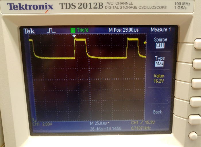
With a 'scope hooked to the battery we
see this:
[img]cid:.0[/img]
Yeah, it 'hammers' the battery with 25uS, 16v pulses
probably 2A or better at an 8.2KHz rate.
I saw no signals that suggested credence for the
magic 3.26Mhz 'resonant frequency' of lead sulfate . . .
which I think is bogus. How any physical mass of
those dimensions might offer resonance at a
wavelength of 97 meters begs some light-
footed explanation.
Nonetheless, the product does have a 'hammer'
mode. The literature suggests that a badly sulfated
battery may require weeks of rejuvenation . . . this
test article is in pretty bad shape so we'll
let 'er cook.
BTW I see that BatteryMinder has come out with
a 'desulfator' product.
https://tinyurl.com/y4682h48
 Bob . . .
|
| | - The Matronics AeroElectric-List Email Forum - | | | Use the List Feature Navigator to browse the many List utilities available such as the Email Subscriptions page, Archive Search & Download, 7-Day Browse, Chat, FAQ, Photoshare, and much more:
http://www.matronics.com/Navigator?AeroElectric-List |
|
| Description: |
|
| Filesize: |
255.3 KB |
| Viewed: |
6475 Time(s) |
|
|
|
| Back to top |
|
 |
ceengland7(at)gmail.com
Guest
|
| Posted: Fri Mar 29, 2019 12:04 pm Post subject: Piper Arrow Pitot Mast |
|
|
On 3/29/2019 11:36 AM, William Hunter wrote:
| Quote: | Greetings,
Does anybody happen to have a manual or specifications sheet for a
Piper Arrow pitot-static mast?
What amp rating circuit breaker should I use to protect this circuit
(I am using 12 AWG Tefzel wire)?
 I have one of these installed on my experimental airplane and I would
like to have some kind of instruction sheet for each component
installed and this is one of the last items I do not have an
instruction sheet on.
Thanks!!!
Bill Hunter
The breaker should protect the wire, so just use a chart that gives max
|
capacity for #12 wire.
Are there no brand/model markings on the mast? It seems likely that
Piper would just buy a common part.
Charlie
---
This email has been checked for viruses by Avast antivirus software.
https://www.avast.com/antivirus
| | - The Matronics AeroElectric-List Email Forum - | | | Use the List Feature Navigator to browse the many List utilities available such as the Email Subscriptions page, Archive Search & Download, 7-Day Browse, Chat, FAQ, Photoshare, and much more:
http://www.matronics.com/Navigator?AeroElectric-List |
|
|
|
| Back to top |
|
|
fvalarm(at)rapidnet.net
Guest
|
| Posted: Mon Apr 01, 2019 2:33 pm Post subject: Piper Arrow Pitot Mast |
|
|
The proper way is to measure the sustained current draw for that pitot (at the voltage the alternator will put out, ie 14volts), then size a wire appropriately taking into consideration the total length of the run, then select a breaker to protect that size of wire. Anything else is just guessing.
Bevan
On 3/29/2019 9:36 AM, William Hunter wrote:
| Quote: | Greetings,Â
Does anybody happen to have a manual or specifications sheet for a Piper Arrow pitot-static mast?
What amp rating circuit breaker should I use to protect this circuit (I am using 12 AWG Tefzel wire)?Â
 I have one of these installed on my experimental airplane and I would like to have some kind of instruction sheet for each component installed and this is one of the last items I do not have an instruction sheet on.
Thanks!!!Â
Bill Hunter
On Tue, Mar 26, 2019, 15:23 Robert L. Nuckolls, III <nuckolls.bob(at)aeroelectric.com (nuckolls.bob(at)aeroelectric.com)> wrote:
| Quote: | The latest/greatest specimin in the
stable of Battery Tender wall warts
came in.
I dug around in the shop and came up
with an SVLA battery out of a portable
air compressor that showed about 9v
open circuit. When impressed with 14.2
volts, charge current stabilized at
about 0.4 amps and would not go any
lower. After being on charge for about
5 hours, I loaded it with 1A and the
terminal voltage fell to about 11 volts.
I.e. capacity of zero.
I deduce that no cells are shorted.
I hooked it to the new Battery
Tender and invoked the maintenance
mode.
Here are the pertinent pages from the
users manual.
http://www.aeroelectric.com/articles/Batteries/Battery_Tender.pdf
With a 'scope hooked to the battery we
see this:
[img]cid:.0[/img]
Yeah, it 'hammers' the battery with 25uS, 16v pulses
probably 2A or better at an 8.2KHz rate.
I saw no signals that suggested credence for the
magic 3.26Mhz 'resonant frequency' of lead sulfate . . .
which I think is bogus. How any physical mass of
those dimensions might offer resonance at a
wavelength of 97 meters begs some light-
footed explanation.
Nonetheless, the product does have a 'hammer'
mode. The literature suggests that a badly sulfated
battery may require weeks of rejuvenation . . . this
test article is in pretty bad shape so we'll
let 'er cook.
BTW I see that BatteryMinder has come out with
a 'desulfator' product.
https://tinyurl.com/y4682h48
 Bob . . .
|
--
Bevan Tomm
Senior Technician
Fraser Valley Alarm Services Inc.
bevan(at)fvas.bc.ca (bevan(at)fvas.bc.ca)
office 604-854-2994
Fax 604-852-6408 |
 Virus-free. www.avg.com [url=#DAB4FAD8-2DD7-40BB-A1B8-4E2AA1F9FDF2] [/url] Virus-free. www.avg.com [url=#DAB4FAD8-2DD7-40BB-A1B8-4E2AA1F9FDF2] [/url]
| | - The Matronics AeroElectric-List Email Forum - | | | Use the List Feature Navigator to browse the many List utilities available such as the Email Subscriptions page, Archive Search & Download, 7-Day Browse, Chat, FAQ, Photoshare, and much more:
http://www.matronics.com/Navigator?AeroElectric-List |
|
|
|
| Back to top |
|
|
nuckolls.bob(at)aeroelect
Guest
|
| Posted: Mon Apr 01, 2019 4:19 pm Post subject: Piper Arrow Pitot Mast |
|
|
At 05:32 PM 4/1/2019, you wrote:
| Quote: | | The proper way is to measure the sustained current draw for that pitot (at the voltage the alternator will put out, ie 14volts), then size a wire appropriately taking into consideration the total length of the run, then select a breaker to protect that size of wire. Anything else is just guessing. |
Pitot tube heaters are a special breed
of cat. I published a performance narrative
on a popular pitot tube about 13 years
ago . . .
https://tinyurl.com/y78oc7z3
In this document I describe the prolonged
and pronounced inrush currents impressed
on the system during during warm up.
A 150W (typical) tube will draw right
at 10A on a 14V airplane. Warmup
from cold will start at about 2x
that value and take tens of seconds.
Extended warm-up loading may well nuisance
trip a breaker rated for wire carrying
running currents.
Just for grins, I suggest your
12AWG wire protected with a 20A
breaker would be judiciously
oversized.
Bob . . .
| | - The Matronics AeroElectric-List Email Forum - | | | Use the List Feature Navigator to browse the many List utilities available such as the Email Subscriptions page, Archive Search & Download, 7-Day Browse, Chat, FAQ, Photoshare, and much more:
http://www.matronics.com/Navigator?AeroElectric-List |
|
|
|
| Back to top |
|
|
roughleg(at)gmail.com
Guest
|
| Posted: Mon Apr 01, 2019 8:42 pm Post subject: Piper Arrow Pitot Mast |
|
|
Bob,
If I measure the resistance of my pitot heater elements at room temperature and calculate the current thru each of these two resistances in parallel when driven by a 14V supply, how far off am I for deducing peak inrush current in each circuit and thus wire size and breaker rating?Â
Pat
On Mon, Apr 1, 2019 at 6:24 PM Robert L. Nuckolls, III <nuckolls.bob(at)aeroelectric.com (nuckolls.bob(at)aeroelectric.com)> wrote:
| Quote: | At 05:32 PM 4/1/2019, you wrote:
| Quote: | | The proper way is to measure the sustained current draw for that pitot (at the voltage the alternator will put out, ie 14volts), then size a wire appropriately taking into consideration the total length of the run, then select a breaker to protect that size of wire.ÃÂ Anything else is just guessing. |
 Pitot tube heaters are a special breed
 of cat. I published a performance narrative
 on a popular pitot tube about 13 years
 ago . . .
https://tinyurl.com/y78oc7z3
 In this document I describe the prolonged
 and pronounced inrush currents impressed
 on the system during during warm up.
 A 150W (typical) tube will draw right
 at 10A on a 14V airplane. Warmup
 from cold will start at about 2x
 that value and take tens of seconds.
 Extended warm-up loading may well nuisance
 trip a breaker rated for wire carrying
 running currents.
 Just for grins, I suggest your
 12AWG wire protected with a 20A
 breaker would be judiciously
 oversized.
 Bob . . .
|
| | - The Matronics AeroElectric-List Email Forum - | | | Use the List Feature Navigator to browse the many List utilities available such as the Email Subscriptions page, Archive Search & Download, 7-Day Browse, Chat, FAQ, Photoshare, and much more:
http://www.matronics.com/Navigator?AeroElectric-List |
|
|
|
| Back to top |
|
|
nuckolls.bob(at)aeroelect
Guest
|
| Posted: Tue Apr 02, 2019 4:44 am Post subject: Piper Arrow Pitot Mast |
|
|
At 11:40 PM 4/1/2019, you wrote:
| Quote: | Bob,
If I measure the resistance of my pitot heater elements at room temperature and calculate the current thru each of these two resistances in parallel when driven by a 14V supply, how far off am I for deducing peak inrush current in each circuit and thus wire size and breaker rating? |
Two resistances? Is this a 12/24v
device? I've never seen one but that
would kind of make sense.
Yes, but they are LOW resistances.
You need to do the 4-wire method
to measure them accurately. I think
you're fine with 20A/12AWG . . . plenty
robust, not overkill.
Bob . . .
| | - The Matronics AeroElectric-List Email Forum - | | | Use the List Feature Navigator to browse the many List utilities available such as the Email Subscriptions page, Archive Search & Download, 7-Day Browse, Chat, FAQ, Photoshare, and much more:
http://www.matronics.com/Navigator?AeroElectric-List |
|
|
|
| Back to top |
|
|
alec(at)alecmyers.com
Guest
|
| Posted: Tue Apr 02, 2019 5:21 am Post subject: Piper Arrow Pitot Mast |
|
|
Do you think the weather might make a difference?
Inrush current when switched on at -20C might be higher than inrush current at room temperature.
On Apr 2, 2019, at 8:43 AM, Robert L. Nuckolls, III <nuckolls.bob(at)aeroelectric.com> wrote:
At 11:40 PM 4/1/2019, you wrote:
| Quote: | Bob,
If I measure the resistance of my pitot heater elements at room temperature and calculate the current thru each of these two resistances in parallel when driven by a 14V supply, how far off am I for deducing peak inrush current in each circuit and thus wire size and breaker rating?Ã
|
Two resistances? Is this a 12/24v
device? I've never seen one but that
would kind of make sense.
Yes, but they are LOW resistances.
You need to do the 4-wire method
to measure them accurately. I think
you're fine with 20A/12AWG . . . plenty
robust, not overkill.
Bob . . .
| | - The Matronics AeroElectric-List Email Forum - | | | Use the List Feature Navigator to browse the many List utilities available such as the Email Subscriptions page, Archive Search & Download, 7-Day Browse, Chat, FAQ, Photoshare, and much more:
http://www.matronics.com/Navigator?AeroElectric-List |
|
|
|
| Back to top |
|
|
roughleg(at)gmail.com
Guest
|
| Posted: Tue Apr 02, 2019 6:13 am Post subject: Piper Arrow Pitot Mast |
|
|
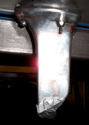
The pitot head is from a Cherokee, looks like this
[img]cid:ii_jtzujnjo0[/img]
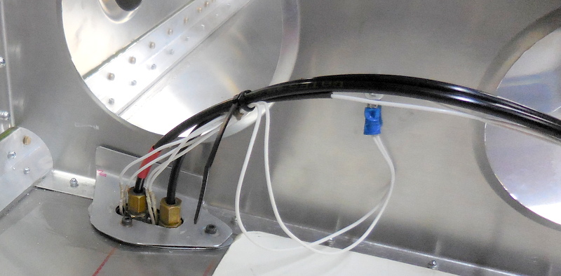
Here's a picture of the wiring inside the wing during construction
[img]cid:ii_jtzuk28o1[/img]
which looks possibly like two circuits in parallel.
The wing is closed up now, so I can only investigate at the wing root where there are two wires for pitot heat, let's call them A and B. The resistances I measure (with a multimeter) are
A to ground 2.9 Ohm
B to ground 3.7 Ohm
A to B (i.e., in series) 6.4 Ohm
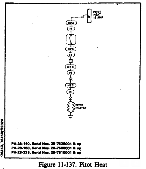
In trying to understand what is going on I dug into the internet and found a PA-28 service manual (don't know if this is the same model of pitot mast or not) which had this diagram
[img]cid:ii_jtzuqlmi2[/img]
which shows two resistors in parallel, although only one circuit supplying their current.Â
So, my deduction is I have two parallel resistors and two wires to feed them - the wires in the wing are 18AWG.
My room-temperature resistance readings may not be accurate (not 4-wire) or relevant (per Alec's comment about turn on at low temps) but doing a simple calculation I would have 14/2.9 = 5A and 14/3.7 = 4A for a total of 9A at room temp.
I can see that designing for 20A 12AWG (for the wires I'll be adding inside the fuselage) would give me a good margin. I wonder about the 18AWG wires in the wing though.
Pat
On Tue, Apr 2, 2019 at 6:49 AM Robert L. Nuckolls, III <nuckolls.bob(at)aeroelectric.com (nuckolls.bob(at)aeroelectric.com)> wrote:
| Quote: | At 11:40 PM 4/1/2019, you wrote:
| Quote: | Bob,
If I measure the resistance of my pitot heater elements at room temperature and calculate the current thru each of these two resistances in parallel when driven by a 14V supply, how far off am I for deducing peak inrush current in each circuit and thus wire size and breaker rating?Ã |
 Two resistances? Is this a 12/24v
 device? I've never seen one but that
 would kind of make sense.
 Yes, but they are LOW resistances.
 You need to do the 4-wire method
 to measure them accurately. I think
 you're fine with 20A/12AWG . . . plenty
 robust, not overkill.
 Bob . . .
|
| | - The Matronics AeroElectric-List Email Forum - | | | Use the List Feature Navigator to browse the many List utilities available such as the Email Subscriptions page, Archive Search & Download, 7-Day Browse, Chat, FAQ, Photoshare, and much more:
http://www.matronics.com/Navigator?AeroElectric-List |
|
| Description: |
|
| Filesize: |
43.86 KB |
| Viewed: |
6434 Time(s) |
|
| Description: |
|
| Filesize: |
126.52 KB |
| Viewed: |
6434 Time(s) |

|
| Description: |
|
| Filesize: |
47.4 KB |
| Viewed: |
6434 Time(s) |

|
|
|
| Back to top |
|
|
billhuntersemail(at)gmail
Guest
|
| Posted: Tue Apr 02, 2019 6:38 am Post subject: Piper Arrow Pitot Mast |
|
|
Pat, that is precisely the pitot mast that I have installed on my airplane except mine does not have the duct tape upgrade.Â
Thank you for the shot of the service manual and thanks so much everybody for all your help!
Thanks,
Bill Hunter
On Tue, Apr 2, 2019, 07:21 Pat Little <roughleg(at)gmail.com (roughleg(at)gmail.com)> wrote:
| Quote: | The pitot head is from a Cherokee, looks like this
[img]https://mail.google.com/mail/?ui=2&ik=12ae5e93ee&attid=0.3&th=169de7bb9eae9ab9&view=fimg&rm=169de7bb9eae9ab9&sz=w1600-h1000&attbid=ANGjdJ8qmFLifUjSQRN4Y9L2EDeXRypIyZS5Yn-PpRaddydiO5wNIz1qrvhbQINjTDlQVYk3uxGiB8-vv9ewYdtiyq-Of9sRRL3OnXANrAR1am57cRU4Gl8OfBiaw3A&disp=emb&realattid=ii_jtzujnjo0&zw[/img]
Here's a picture of the wiring inside the wing during construction
[img]https://mail.google.com/mail/?ui=2&ik=12ae5e93ee&attid=0.1&th=169de7bb9eae9ab9&view=fimg&rm=169de7bb9eae9ab9&sz=w1600-h1000&attbid=ANGjdJ8iaa62WqooBfWf8kt00iC1b-Qqs4tM9vVIDLCsS884IxI2rTpOyIu1sd5yE6hJxUDVLpPDulk4XsG-vxXPcEqttJBk3aaR0J_c6qmtYS8eXd3vcl34KAUEZMk&disp=emb&realattid=ii_jtzuk28o1&zw[/img]
which looks possibly like two circuits in parallel.
The wing is closed up now, so I can only investigate at the wing root where there are two wires for pitot heat, let's call them A and B. The resistances I measure (with a multimeter) are
A to ground 2.9 Ohm
B to ground 3.7 Ohm
A to B (i.e., in series) 6.4 Ohm
In trying to understand what is going on I dug into the internet and found a PA-28 service manual (don't know if this is the same model of pitot mast or not) which had this diagram
[img]https://mail.google.com/mail/?ui=2&ik=12ae5e93ee&attid=0.2&th=169de7bb9eae9ab9&view=fimg&rm=169de7bb9eae9ab9&sz=w1600-h1000&attbid=ANGjdJ9-2Y97fI4B5FjUnrTZrTDj4mNGUJmeQjqWcECfUENP53YyavRslhVMRoD8tVEwcTcsun60bC1LUc2tKeNG5IakuAt-re8yLjxiBRwzqo7x2ey0zEV2eQvp4Nw&disp=emb&realattid=ii_jtzuqlmi2&zw[/img]
which shows two resistors in parallel, although only one circuit supplying their current.Â
So, my deduction is I have two parallel resistors and two wires to feed them - the wires in the wing are 18AWG.
My room-temperature resistance readings may not be accurate (not 4-wire) or relevant (per Alec's comment about turn on at low temps) but doing a simple calculation I would have 14/2.9 = 5A and 14/3.7 = 4A for a total of 9A at room temp.
I can see that designing for 20A 12AWG (for the wires I'll be adding inside the fuselage) would give me a good margin. I wonder about the 18AWG wires in the wing though.
Pat
On Tue, Apr 2, 2019 at 6:49 AM Robert L. Nuckolls, III <nuckolls.bob(at)aeroelectric.com (nuckolls.bob(at)aeroelectric.com)> wrote:
| Quote: | At 11:40 PM 4/1/2019, you wrote:
| Quote: | Bob,
If I measure the resistance of my pitot heater elements at room temperature and calculate the current thru each of these two resistances in parallel when driven by a 14V supply, how far off am I for deducing peak inrush current in each circuit and thus wire size and breaker rating?Ã |
 Two resistances? Is this a 12/24v
 device? I've never seen one but that
 would kind of make sense.
 Yes, but they are LOW resistances.
 You need to do the 4-wire method
 to measure them accurately. I think
 you're fine with 20A/12AWG . . . plenty
 robust, not overkill.
 Bob . . .
|
|
| | - The Matronics AeroElectric-List Email Forum - | | | Use the List Feature Navigator to browse the many List utilities available such as the Email Subscriptions page, Archive Search & Download, 7-Day Browse, Chat, FAQ, Photoshare, and much more:
http://www.matronics.com/Navigator?AeroElectric-List |
|
|
|
| Back to top |
|
|
rnadms(at)gmail.com
Guest
|
| Posted: Tue Apr 02, 2019 6:42 am Post subject: Piper Arrow Pitot Mast |
|
|
Hey Pat
I used to fly one of these on a Seneca
Every time I got into ice it froze over and I lost the airspeed indicator (which made it quite handy as an ice detector)
Was told it was a design flaw... it didnât have enough capacity to heat the mass of the probe sufficientlyÂ
All the best!
Ron
On Tue, Apr 2, 2019 at 10:21 AM Pat Little <roughleg(at)gmail.com (roughleg(at)gmail.com)> wrote:
| Quote: | The pitot head is from a Cherokee, looks like this
[img]cid:ii_jtzujnjo0[/img]
Here's a picture of the wiring inside the wing during construction
[img]cid:ii_jtzuk28o1[/img]
which looks possibly like two circuits in parallel.
The wing is closed up now, so I can only investigate at the wing root where there are two wires for pitot heat, let's call them A and B. The resistances I measure (with a multimeter) are
A to ground 2.9 Ohm
B to ground 3.7 Ohm
A to B (i.e., in series) 6.4 Ohm
In trying to understand what is going on I dug into the internet and found a PA-28 service manual (don't know if this is the same model of pitot mast or not) which had this diagram
[img]cid:ii_jtzuqlmi2[/img]
which shows two resistors in parallel, although only one circuit supplying their current.Â
So, my deduction is I have two parallel resistors and two wires to feed them - the wires in the wing are 18AWG.
My room-temperature resistance readings may not be accurate (not 4-wire) or relevant (per Alec's comment about turn on at low temps) but doing a simple calculation I would have 14/2.9 = 5A and 14/3.7 = 4A for a total of 9A at room temp.
I can see that designing for 20A 12AWG (for the wires I'll be adding inside the fuselage) would give me a good margin. I wonder about the 18AWG wires in the wing though.
Pat
On Tue, Apr 2, 2019 at 6:49 AM Robert L. Nuckolls, III <nuckolls.bob(at)aeroelectric.com (nuckolls.bob(at)aeroelectric.com)> wrote:
| Quote: | At 11:40 PM 4/1/2019, you wrote:
| Quote: | Bob,
If I measure the resistance of my pitot heater elements at room temperature and calculate the current thru each of these two resistances in parallel when driven by a 14V supply, how far off am I for deducing peak inrush current in each circuit and thus wire size and breaker rating?Ã |
 Two resistances? Is this a 12/24v
 device? I've never seen one but that
 would kind of make sense.
 Yes, but they are LOW resistances.
 You need to do the 4-wire method
 to measure them accurately. I think
 you're fine with 20A/12AWG . . . plenty
 robust, not overkill.
 Bob . . .
|
|
| | - The Matronics AeroElectric-List Email Forum - | | | Use the List Feature Navigator to browse the many List utilities available such as the Email Subscriptions page, Archive Search & Download, 7-Day Browse, Chat, FAQ, Photoshare, and much more:
http://www.matronics.com/Navigator?AeroElectric-List |
|
| Description: |
|
| Filesize: |
43.86 KB |
| Viewed: |
6434 Time(s) |

|
| Description: |
|
| Filesize: |
126.52 KB |
| Viewed: |
6434 Time(s) |
|
| Description: |
|
| Filesize: |
47.4 KB |
| Viewed: |
6434 Time(s) |
|
|
|
| Back to top |
|
|
nuckolls.bob(at)aeroelect
Guest
|
| Posted: Tue Apr 02, 2019 10:32 am Post subject: Piper Arrow Pitot Mast |
|
|
At 08:20 AM 4/2/2019, you wrote:
| Quote: | --> AeroElectric-List message posted by: Alec Myers <alec(at)alecmyers.com>
Do you think the weather might make a difference?
Inrush current when switched on at -20C might be higher than inrush current at room temperature. |
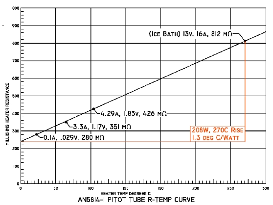
Sure. The document I cited speaks to
the heater temperature coefficient of
resistance for an exemplar pitot tube.
[img]cid:7.1.0.9.0.20190402132145.0606f2b0(at)aeroelectric.com.0[/img]
In the instance illustrated, resistance
will vary over a 4:1 range between 0C and
the 270C operation during a max-ice
condition. You can check your heater on
the bench but do it will the tube
submerged in water to avoid still-air,
room-temperature overheat. Without
the heat rejecting qualities of ram-
air in near-icing conditions, the tube
will easily heat up to cherry red!
Bob . . .
| | - The Matronics AeroElectric-List Email Forum - | | | Use the List Feature Navigator to browse the many List utilities available such as the Email Subscriptions page, Archive Search & Download, 7-Day Browse, Chat, FAQ, Photoshare, and much more:
http://www.matronics.com/Navigator?AeroElectric-List |
|
| Description: |
|
| Filesize: |
91.16 KB |
| Viewed: |
6430 Time(s) |
|
|
|
| Back to top |
|
|
nuckolls.bob(at)aeroelect
Guest
|
| Posted: Tue Apr 02, 2019 11:58 am Post subject: Piper Arrow Pitot Mast |
|
|
A
| Quote: | which shows two resistors in parallel, although only one circuit supplying their current.
So, my deduction is I have two parallel resistors and two wires to feed them - the wires in the wing are 18AWG. |
The wires will be fine . . . tie them together
at some convenient point you can reach, then
extend on to switch with the 12AWG wire.
The drawing shows 15A breaker which is also
fine.
| Quote: | My room-temperature resistance readings may not be accurate (not 4-wire) or relevant (per Alec's comment about turn on at low temps) but doing a simple calculation I would have 14/2.9 = 5A and 14/3.7 = 4A for a total of 9A at room temp.
I can see that designing for 20A 12AWG (for the wires I'll be adding inside the fuselage) would give me a good margin. I wonder about the 18AWG wires in the wing though. |
Yeah . . . 9A at room temp will
go lower at operating temperature
unless melting ice. Sounds like
not much of a heater . . . which
sorta agrees with other folks
experiences with poor performance.
Pitot heat really isn't much of
a hedge against a bad day in the
cockpit. If you're collecting
ice, airspeed is probably the least
of your worries. I could tell
you a tale or two about that.
Wire it up but don't let its
existence dissuade you from due
diligence with the weather-guys
while you're still on the ground.
Bob . . .
| | - The Matronics AeroElectric-List Email Forum - | | | Use the List Feature Navigator to browse the many List utilities available such as the Email Subscriptions page, Archive Search & Download, 7-Day Browse, Chat, FAQ, Photoshare, and much more:
http://www.matronics.com/Navigator?AeroElectric-List |
|
|
|
| Back to top |
|
|
roughleg(at)gmail.com
Guest
|
| Posted: Wed Apr 03, 2019 7:03 am Post subject: Piper Arrow Pitot Mast |
|
|
Thanks, Ron. I like the idea of an ice detector!
On Tue, Apr 2, 2019 at 8:48 AM R Adams <rnadms(at)gmail.com (rnadms(at)gmail.com)> wrote:
| Quote: | Hey Pat
I used to fly one of these on a Seneca
Every time I got into ice it froze over and I lost the airspeed indicator (which made it quite handy as an ice detector)
Was told it was a design flaw... it didnât have enough capacity to heat the mass of the probe sufficientlyÂ
All the best!
Ron
|
| | - The Matronics AeroElectric-List Email Forum - | | | Use the List Feature Navigator to browse the many List utilities available such as the Email Subscriptions page, Archive Search & Download, 7-Day Browse, Chat, FAQ, Photoshare, and much more:
http://www.matronics.com/Navigator?AeroElectric-List |
|
|
|
| Back to top |
|
|
|
|
You cannot post new topics in this forum
You cannot reply to topics in this forum
You cannot edit your posts in this forum
You cannot delete your posts in this forum
You cannot vote in polls in this forum
You cannot attach files in this forum
You can download files in this forum
|
Powered by phpBB © 2001, 2005 phpBB Group
|

