 |
Matronics Email Lists
Web Forum Interface to the Matronics Email Lists
|
| View previous topic :: View next topic |
| Author |
Message |
frank3
Guest
|
 Posted: Sat Feb 19, 2011 5:57 pm Post subject: Voltage Regulator Problem Posted: Sat Feb 19, 2011 5:57 pm Post subject: Voltage Regulator Problem |
 |
|
I have a 912ULS with the Ducati regulator wired into the Z16 diagram that I have been flying for three years.  Today on run-up I noted low voltage (<11 volts) in the Grand Rapid EIS & the Dynon EFIS displays, regardless of RPM. Normally I get 13.1 volts indicated with load.


With Master off & engine not running the yellow dynamo wires feeding the regulator show continuity with no resistance.  I am thinking there should be some resistance--am I correct or is the reading OK?  At fast idle (2400 RPM) the yellow wires indicate 18 volts AC and correspondingly increases with increasing RPM.  The regulator output B+ terminal reads 8.5 volts DC--I believe I should expect 14 v DC.  The system voltmeter reads ~11 volts with minimal load.  Battery was 12.5 v.  I traded out the regulator with one that I was told was good.  Very similar results (8.3 volts output).  I assume both regulators are faulty???  Any suggestions to further trouble shoot?


If I replace the regulator I'm considering the Key West.  Question about integrating into the Z16 wiring scheme.  I assume the + & - input terminals are connected to the yellow wires from the dynamo.  Not sure how to hook-up the + & - output terminals.  Can anyone help me with that?


Thanks much
| | - The Matronics AeroElectric-List Email Forum - | | | Use the List Feature Navigator to browse the many List utilities available such as the Email Subscriptions page, Archive Search & Download, 7-Day Browse, Chat, FAQ, Photoshare, and much more:
http://www.matronics.com/Navigator?AeroElectric-List |
|
|
|
| Back to top |
|
 |
frank3
Guest
|
| Posted: Sun Feb 20, 2011 6:34 am Post subject: Re: Voltage Regulator Problem |
|
|
Let me try sending again--only part of note came through on first try.


 I have a 912ULS with the Ducati regulator wired into the Z16 diagram that I have been flying for three years. Today on run-up I noted low voltage (under 11 volts) in the Grand Rapid EIS & the Dynon EFIS displays, regardless of RPM. Normally I get 13.1 volts indicated with load.


With Master off & engine not running the yellow dynamo wires feeding the regulator show continuity with no resistance. I am thinking there should be some resistance--am I correct or is the reading OK? At fast idle (2400 RPM) the yellow wires indicate 18 volts AC and correspondingly increases with increasing RPM. The regulator output B+ terminal reads 8.5 volts DC--I believe I should expect 14 v DC. The system voltmeter reads about 11 volts with minimal load. Battery was 12.5 v. I traded out the regulator with one that I was told was good. Very similar results (8.3 volts output). I assume both regulators are faulty??? Any suggestions to further trouble shoot?


If I replace the regulator I'm considering the Key West. Question about integrating into the Z16 wiring scheme. I assume the + & - input terminals are connected to the yellow wires from the dynamo. Not sure how to hook-up the + & - output terminals. Can anyone help me with that?


Thanks much
| | - The Matronics AeroElectric-List Email Forum - | | | Use the List Feature Navigator to browse the many List utilities available such as the Email Subscriptions page, Archive Search & Download, 7-Day Browse, Chat, FAQ, Photoshare, and much more:
http://www.matronics.com/Navigator?AeroElectric-List |
|
|
|
| Back to top |
|
|
nuckolls.bob(at)aeroelect
Guest
|
| Posted: Sun Feb 20, 2011 9:56 am Post subject: Voltage Regulator Problem |
|
|
At 09:34 AM 2/20/2011, you wrote:
| Quote: | --> AeroElectric-List message posted by: "frank3" <frank3phyl(at)comcast.net>
Let me try sending again--only part of note came through on first try.
I have a 912ULS with the Ducati regulator wired into the Z16 diagram that I have been flying for three years. Today on run-up I noted low voltage (under 11 volts) in the Grand Rapid EIS & the Dynon EFIS displays, regardless of RPM. Normally I get 13.1 volts indicated with load. |
Alternator/regulator is NOT producing power.
| Quote: | | With Master off & engine not running the yellow dynamo wires feeding the regulator show continuity with no resistance. |
This is a very low resistance . . . less than 1 ohm
that you cannot measure without special attention
to test equipment - like the low ohms adapter on
my website.
| Quote: | | I am thinking there should be some resistance--am I correct or is the reading OK? |
If your plain vanilla volt-ohmeter shows continuity,
the windings are probably fine. Are they discolored,
i.e. insulation very dark and/or cracked?
| Quote: | | At fast idle (2400 RPM) the yellow wires indicate 18 volts AC and correspondingly increases with increasing RPM. |
That's good . . .
| Quote: | | The regulator output B+ terminal reads 8.5 volts DC--I believe I should expect 14 v DC. The system voltmeter reads about 11 volts with minimal load. Battery was 12.5 v. I traded out the regulator with one that I was told was good. Very similar results (8.3 volts output). I assume both regulators are faulty??? Any suggestions to further trouble shoot? |
Is your control relay closing? Try bypassing the
OV/control system and connect your R/R output
wire directly to the system (unplug fat wires
from relay and connect them together). Then
do your voltage checks.
| Quote: | | If I replace the regulator I'm considering the Key West. Question about integrating into the Z16 wiring scheme. I assume the + & - input terminals are connected to the yellow wires from the dynamo. Not sure how to hook-up the + & - output terminals. Can anyone help me with that? |
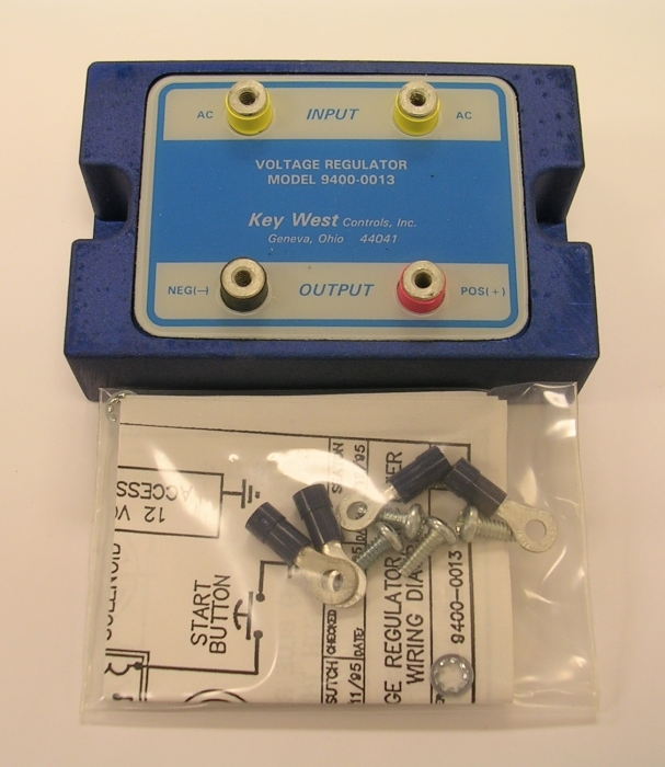
Do you have the Key West installation instructions?
If it is this device:
[img]cid:7.1.0.9.0.20110220113902.01fbed20(at)aeroelectric.com.0[/img]
The terminal markings are pretty definitive. AC input is from
your alternator winding, NEG(-) goes to ground, POS(+) would
go to the control relay.
But check your control relay closure first. It seems unlikely that
you would suffer TWO Rectifier/Regulator failures.
Bob . . .
| | - The Matronics AeroElectric-List Email Forum - | | | Use the List Feature Navigator to browse the many List utilities available such as the Email Subscriptions page, Archive Search & Download, 7-Day Browse, Chat, FAQ, Photoshare, and much more:
http://www.matronics.com/Navigator?AeroElectric-List |
|
| Description: |
|
| Filesize: |
281.54 KB |
| Viewed: |
11140 Time(s) |
|
|
|
| Back to top |
|
|
frank3
Guest
|
| Posted: Sun Feb 20, 2011 1:44 pm Post subject: Re: Voltage Regulator Problem |
|
|
Bob

Thanks for your input.

As you suggested I removed the relay "C" input and jumped it across to the "A" lead.  The reading from the regulator B+ lead was initially about 11 volts with the engine running but steadily decreased to yesterday's reading of about 8.4 volts.  Reading was not influenced by increase in RPM.


I reconnected to the relay "C" terminal and took a reading from the "C" terminal to the starter relay to check the circuit through the relay & across the fuse link and got a reading of 8.3 volts with the master on ALT.  Battery still above 12 v.


Any other suggestions?
| | - The Matronics AeroElectric-List Email Forum - | | | Use the List Feature Navigator to browse the many List utilities available such as the Email Subscriptions page, Archive Search & Download, 7-Day Browse, Chat, FAQ, Photoshare, and much more:
http://www.matronics.com/Navigator?AeroElectric-List |
|
|
|
| Back to top |
|
|
nuckolls.bob(at)aeroelect
Guest
|
| Posted: Sun Feb 20, 2011 10:25 pm Post subject: Voltage Regulator Problem |
|
|
At 04:44 PM 2/20/2011, you wrote:
| Quote: |
Bob
Thanks for your input.
As you suggested I removed the relay "C" input and jumped it across
to the "A" lead. The reading from the regulator B+ lead was
initially about 11 volts with the engine running but steadily
decreased to yesterday's reading of about 8.4 volts. Reading was
not influenced by increase in RPM.
I reconnected to the relay "C" terminal and took a reading from the
"C" terminal to the starter relay to check the circuit through the
relay & across the fuse link and got a reading of 8.3 volts with the
master on ALT. Battery still above 12 v.
|
It's not clear that you understood my suggestion.
I intended that you bypass the control relay
entirely. If you're using Z-16 of more than 3
years ago, then the relay is probably in the DC
output wire from the rectifier-regulator. The
current version uses the control relay to switch
AC power out of the alternator.
Unplug both the heavy gage wires from the control
relay and connect them together thus eliminating
the relay as a means by which the alternator can
be disconnected from the system.
Then see how things perform. The point of this
experiment is to eliminate the relay and its
control wiring as potential cause for your
observed malfunction.
While the relay is bypassed and you're making
other voltage measurements, see what voltage you
read on the relay's skinny wires too with the
battery/alternator control switch full up. One
should be seeing battery voltage, the other
should be zero volts.
Bob . . .
| | - The Matronics AeroElectric-List Email Forum - | | | Use the List Feature Navigator to browse the many List utilities available such as the Email Subscriptions page, Archive Search & Download, 7-Day Browse, Chat, FAQ, Photoshare, and much more:
http://www.matronics.com/Navigator?AeroElectric-List |
|
|
|
| Back to top |
|
|
frank3
Guest
|
| Posted: Mon Feb 21, 2011 8:51 am Post subject: Re: Voltage Regulator Problem |
|
|
Bob

Thanks for clarifying.


With relay circumvented (fat wires disconnected from relay but joined together), B+ = 11.6v steady; EIS steady 10.8v.  No change to either reading with RPM increase.


Re the "little wires", neither had voltage with master on ALT.


Reconnected relay and retested, B+ = 1.9v at start and slowly increased to 4v after 10 min engine run.  Same reading immediately after engine off.  EIS showed 10.8v.  No change to either reading with RPM increase.


Further suggestions/assessment?
| | - The Matronics AeroElectric-List Email Forum - | | | Use the List Feature Navigator to browse the many List utilities available such as the Email Subscriptions page, Archive Search & Download, 7-Day Browse, Chat, FAQ, Photoshare, and much more:
http://www.matronics.com/Navigator?AeroElectric-List |
|
|
|
| Back to top |
|
|
nuckolls.bob(at)aeroelect
Guest
|
| Posted: Mon Feb 21, 2011 9:13 am Post subject: Voltage Regulator Problem |
|
|
At 11:51 AM 2/21/2011, you wrote:
| Quote: |
Bob
Thanks for clarifying.
With relay circumvented (fat wires disconnected from relay but
joined together), B+ = 11.6v steady; EIS steady 10.8v. No change to
either reading with RPM increase.
|
Okay, this says the rectifier/regulator is bad
| Quote: | Re the "little wires", neither had voltage with master on ALT.
|
????? Double failure ???? If there's no power
coming from the alternator switch, then you're
certainly not going to get the alternator on
line.
Trace the power flow from the bus through the
ALT switch to the relay.
Bob . . .
| | - The Matronics AeroElectric-List Email Forum - | | | Use the List Feature Navigator to browse the many List utilities available such as the Email Subscriptions page, Archive Search & Download, 7-Day Browse, Chat, FAQ, Photoshare, and much more:
http://www.matronics.com/Navigator?AeroElectric-List |
|
|
|
| Back to top |
|
|
frank3
Guest
|
| Posted: Mon Feb 21, 2011 12:53 pm Post subject: Re: Voltage Regulator Problem |
|
|
Bob

It is with a very bright red face I offer an apology for the time you've contributed to my issue.  After sending the last note I did as your note suggested--trace the power from the master switch.  After taking the panel out and checking for connections & current flow I ended up at the circuit breaker.  Guess what?  Yes, it had tripped.  After resetting the breaker one of the relay "little wires" showed battery current as you indicated and the regulator B+ showed 14v.  So sorry for not checking the breaker first!  Now I'll have to be on the lookout for whatever caused the breaker to trip the first time.  For me it's been very educational and I thank you.
| | - The Matronics AeroElectric-List Email Forum - | | | Use the List Feature Navigator to browse the many List utilities available such as the Email Subscriptions page, Archive Search & Download, 7-Day Browse, Chat, FAQ, Photoshare, and much more:
http://www.matronics.com/Navigator?AeroElectric-List |
|
|
|
| Back to top |
|
|
nuckolls.bob(at)aeroelect
Guest
|
| Posted: Mon Feb 21, 2011 2:54 pm Post subject: Voltage Regulator Problem |
|
|
At 03:53 PM 2/21/2011, you wrote:


Bob

It is with a very bright red face I offer an apology for the time

you've contributed to my issue.  After sending the last note I did as

your note suggested--trace the power from the master switch.  After

taking the panel out and checking for connections & current flow I

ended up at the circuit breaker.  Guess what?  Yes, it had tripped.


    Hmmm . . . something to add to your future

    LO VOLTS checklist. Do you have a low volts

    warning light? Do you have any notion of when

    the alternator was lost and what was happening

    at the time?


After resetting the breaker one of the relay "little wires" showed

battery current as you indicated and the regulator B+ showed 14v.  So

sorry for not checking the breaker first!  Now I'll have to be on the

lookout for whatever caused the breaker to trip the first time.


    The legacy ovm designs are 99.9% resistant to transient

    events on the system . . . but the reason we

    recommend a breaker as opposed to a fuse is that

    you can reset it ONE TIME after an OV trip just

    to make sure it's a real OV condition and not a

    nuisance trip.


For me it's been very educational and I thank you.


    Your welcome. Nobody ever promised us that

    education was 'cheap' . . . I've had some

    expensive epiphanies over the years. Fortunately

    none resulted in badly bent airplanes or bodily harm

    that wouldn't heal. Lessons hard won at the

    expense of $time$ and frustration are those

    which are best retained.


    The biggest upside of this exchange is that your

    particular set of conditions COULD have been

    root cause for your own (or somebody else's)

    "dark-n-stormy-night" story. By discussing it

    here in embarrassing detail means that interested

    readers can harvest benefits that few stories in

    the flying rags can offer.


    Thank you for sharing . . .


    Bob . . .
| | - The Matronics AeroElectric-List Email Forum - | | | Use the List Feature Navigator to browse the many List utilities available such as the Email Subscriptions page, Archive Search & Download, 7-Day Browse, Chat, FAQ, Photoshare, and much more:
http://www.matronics.com/Navigator?AeroElectric-List |
|
|
|
| Back to top |
|
|
|
|
You cannot post new topics in this forum
You cannot reply to topics in this forum
You cannot edit your posts in this forum
You cannot delete your posts in this forum
You cannot vote in polls in this forum
You cannot attach files in this forum
You can download files in this forum
|
Powered by phpBB © 2001, 2005 phpBB Group
|

