 |
Matronics Email Lists
Web Forum Interface to the Matronics Email Lists
|
| View previous topic :: View next topic |
| Author |
Message |
nuckolls.bob(at)aeroelect
Guest
|
 Posted: Sat Oct 19, 2013 5:10 pm Post subject: EXP 2 Bus workaround Posted: Sat Oct 19, 2013 5:10 pm Post subject: EXP 2 Bus workaround |
 |
|
At 04:01 PM 10/14/2013, you wrote:
| Quote: | On Oct 14, 2013, at 12:16 PM, Ken wrote:
>You are in the ballpark Fred but it's probably safe to round down
>to 20 amps for a no alternator battery life calculation.
Ken...thank you for your "3rd party validation"...at this stage of
the game, I'd rather be conservative, and I'm looking forward to
Bob's assessment.
|
I think I'm down to the last missing data point.
How do you switch between ECU modules? Do you have
a wiring diagram of this feature you can sketch or scan
to share?
Bob . . .
| | - The Matronics AeroElectric-List Email Forum - | | | Use the List Feature Navigator to browse the many List utilities available such as the Email Subscriptions page, Archive Search & Download, 7-Day Browse, Chat, FAQ, Photoshare, and much more:
http://www.matronics.com/Navigator?AeroElectric-List |
|
|
|
| Back to top |
|
 |
Fred Klein
Joined: 26 Mar 2012
Posts: 503
|
| Posted: Sat Oct 19, 2013 6:14 pm Post subject: EXP 2 Bus workaround |
|
|
On Oct 19, 2013, at 6:09 PM, Robert L. Nuckolls, III wrote:
| Quote: | --> AeroElectric-List message posted by: "Robert L. Nuckolls, III" <nuckolls.bob(at)aeroelectric.com (nuckolls.bob(at)aeroelectric.com)>
At 04:01 PM 10/14/2013, you wrote:
| Quote: | On Oct 14, 2013, at 12:16 PM, Ken wrote:
| Quote: | You are in the ballpark Fred but it's probably safe to round down to 20 amps for a no alternator battery life calculation.
|
Ken...thank you for your "3rd party validation"...at this stage of the game, I'd rather be conservative, and I'm looking forward to Bob's assessment.
|
I think I'm down to the last missing data point.
How do you switch between ECU modules? Do you have
a wiring diagram of this feature you can sketch or scan
to share?
Bob . . . |
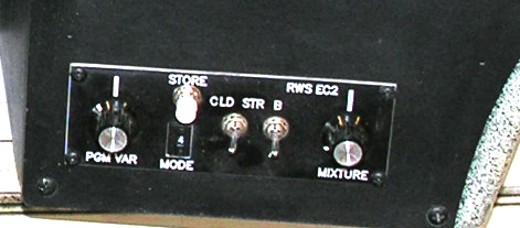
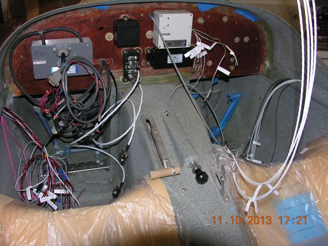
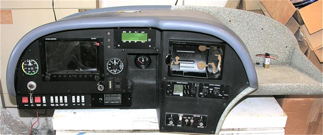
Bob...the guts of the ECU is in a box mounted on the cockpit side of the firewall...is is connected to a small control console mounted on the panel via a D Sub cable. This small control panel includes a switch which toggles between the "A" motherboard and its back up, the "B" motherboard. In the D Sub connector, there are separate power inputs for A and B. I have no wiring diagram explaining this feature. Here is a photo of the panel mounted control console...the toggle switch obscures the "A".
Check it out in the lower right of the panel...then view close up:
[img]cid:059315AC-C223-4B8F-A1CF-7CEDF095E024[/img]
[img]cid:DC3EDB49-7B5F-4EE0-ADD2-61DB66B8EEC1[/img]
| | - The Matronics AeroElectric-List Email Forum - | | | Use the List Feature Navigator to browse the many List utilities available such as the Email Subscriptions page, Archive Search & Download, 7-Day Browse, Chat, FAQ, Photoshare, and much more:
http://www.matronics.com/Navigator?AeroElectric-List |
|
| Description: |
|
| Filesize: |
46.19 KB |
| Viewed: |
9828 Time(s) |

|
| Description: |
|
| Filesize: |
54.63 KB |
| Viewed: |
9828 Time(s) |
|
|
|
| Back to top |
|
|
nuckolls.bob(at)aeroelect
Guest
|
| Posted: Sat Oct 19, 2013 7:56 pm Post subject: EXP 2 Bus workaround |
|
|
| Quote: | Check it out in the lower right of the panel...then view close up:\
|
I guess I missed that in the original set of
photos. Do these separate inputs need to be
switched . . . or is ECU power control accomplished
from the little panel?
Bob . . .
| | - The Matronics AeroElectric-List Email Forum - | | | Use the List Feature Navigator to browse the many List utilities available such as the Email Subscriptions page, Archive Search & Download, 7-Day Browse, Chat, FAQ, Photoshare, and much more:
http://www.matronics.com/Navigator?AeroElectric-List |
|
|
|
| Back to top |
|
|
Fred Klein
Joined: 26 Mar 2012
Posts: 503
|
| Posted: Sat Oct 19, 2013 8:28 pm Post subject: EXP 2 Bus workaround |
|
|
On Oct 19, 2013, at 8:54 PM, Robert L. Nuckolls, III wrote:
| Quote: | | Quote: | Check it out in the lower right of the panel...then view close up:\
|
I guess I missed that in the original set of
photos. Do these separate inputs need to be
switched . . . or is ECU power control accomplished
from the little panel?
|
We will need a switch or circuit breaker between the battery and the ECU...ditto for the fuel injectors, coils, and fuel pumps.
[quote][b]
| | - The Matronics AeroElectric-List Email Forum - | | | Use the List Feature Navigator to browse the many List utilities available such as the Email Subscriptions page, Archive Search & Download, 7-Day Browse, Chat, FAQ, Photoshare, and much more:
http://www.matronics.com/Navigator?AeroElectric-List |
|
|
|
| Back to top |
|
|
klehman(at)albedo.net
Guest
|
| Posted: Sun Oct 20, 2013 12:02 pm Post subject: EXP 2 Bus workaround |
|
|
If this question was for Ken...
On my one off z14 architecture 4 cylinder soob, I run two ecu's all the
time, one off each little battery. Two sets of injectors. Whichever set
of injectors is fed +12 volts flows fuel. If both are on by mistake the
engine loses some power but continues to run but a bit rough. I'm happy
with two switches for this. I don't need or want one either/or switch
although initially I was thinking that two mechanically interconnected
switches might be OK.
Similar with ignition. Whichever set of DIS coils is fed +12 volts feeds
the single plugs through MSD and homemade (polarity issue) HV coil
joiners. Both can be left on indefinitely or for landing and take off
but I only use one at a time.
In steady state cruise 18amps runs my airplane. That includes running
the VHF radio, transponder, intercom, engine monitor, gps, and maybe an
amp (or less) to the battery. If I did not have two alternators I'd size
the battery for about 15 amps for alternator failed operation. Injectors
are about 12 ohms and run 80% duty at full power and in my case about
50% duty in cruise. Ignition is about 5 amps at full power but a little
less in cruise. Similarly the injectors draw a little bit more at full
power but in total only maybe an amp or less difference between full
power and cruise for the complete system.
My system would certainly be overkill for most folks but it has some
unique advantages in terms of simple emergency procedures,
troubleshooting, and redundancy. With recycled parts, the dollar and
weight cost was trivial if not the labor. 530 flight hours on the Murphy
Rebel as of this morning.
Ken
On 19/10/2013 9:09 PM, Robert L. Nuckolls, III wrote:
| Quote: |
<nuckolls.bob(at)aeroelectric.com>
At 04:01 PM 10/14/2013, you wrote:
> On Oct 14, 2013, at 12:16 PM, Ken wrote:
>
>> You are in the ballpark Fred but it's probably safe to round down to
>> 20 amps for a no alternator battery life calculation.
>
> Ken...thank you for your "3rd party validation"...at this stage of the
> game, I'd rather be conservative, and I'm looking forward to Bob's
> assessment.
I think I'm down to the last missing data point.
How do you switch between ECU modules? Do you have
a wiring diagram of this feature you can sketch or scan
to share?
Bob . . .
|
| | - The Matronics AeroElectric-List Email Forum - | | | Use the List Feature Navigator to browse the many List utilities available such as the Email Subscriptions page, Archive Search & Download, 7-Day Browse, Chat, FAQ, Photoshare, and much more:
http://www.matronics.com/Navigator?AeroElectric-List |
|
|
|
| Back to top |
|
|
Fred Klein
Joined: 26 Mar 2012
Posts: 503
|
| Posted: Mon Oct 21, 2013 11:55 am Post subject: EXP 2 Bus workaround |
|
|
All,
I would first of all like to thank all posters who have expanded my understanding of the issues I face as I proceed w/ the wiring of my aircraft...you have already helped me immeasurably to get to the revised (proposed) circuit diagram below.
(I'm quite aware that "numbers" are still missing...but my preference is to get my mind wrapped around the conceptual basis for things before sizing wires.)
With full knowledge of my ignorance of all things electric but with only scant knowledge of the challenges which lay ahead, some time ago I purchased an EXP 2 Bus, thinking that having one would simplify many issues and offset some of the novelty inherent with my auto engine conversion, a MPEFIed derivative of a EA81 Subaru built by RAM Performance Aero Engines which is liquid cooled. Aircraft is a Europa XS monowheel, a fiber glass airframe, which is typically powered w/ a 912S or 914.
I've been struggling to layout a circuit diagram which combines the EXP 2 BUS configured for an external solenoid with the dual battery / single alternator diagram Z-19 in the "AeroElectric Connection".
I have made a number of decisions which have committed me to the digital world including:
- an engine w/ electronic ignition, fuel injection, and an ECU (EC3, Real World Systems) which came w/ the engine,
- a digital EMS (EM3, Real World Systems) which "talks" w/ the ECU,
- a digital EFIS (Skyview) including moving map, digital terrain, Transponder, COM, and Intercom.
By selecting an auto engine conversion, I have committed to:
- one alternator, belt driven,
- one coolant pump, belt driven,
- single spark plug in each cylinder.
Additionally, in order to provide redundancy, the engine and control system includes:
- dual batteries, presently planned to be Odyssey 680's,
- two independent high pressure fuel pumps, each w/ their own filter,
- independent back up battery for Skyview,
- independent back up battery for stand-alone GPS, Garmin 396,
- redundant motherboards (A and B) for the ECU which are toggled from the panel.
OK...about the EXP BUS...I've now read many reports (including the VAF threads) which point out its shortcomings...but having spent $550 for it and its companion Indicator Module, and given my inexperience and lack of knowledge of things electrical, I still believe it has a place in my panel, so I hope any critique of what I'm up to doesn't focus on simply getting rid of it...it sure seems to have value to this electrical neophyte.
The EXP 2 Bus installation instructions can be downloaded at:
http://support.anywheremap.com/pdfs/EXP2-C.pdf
My approach to creating this circuit diagram has been an effort to meld together the EXP Bus w/ the Z-19RB circuit diagram in the AeroElectric Connection for "Dual Battery, Single Alternator, Electronic Controlled Fuel Injection Engine w/ Rear Mounted Batteries"...(a copy of which can be downloaded from:
[url=http://www.aeroelectric.com/PPS/Adobe_Architecture_Pdfs/] http://www.aeroelectric.com/PPS/Adobe_Architecture_Pdfs/[/url]
I could use spare circuits in EXP BUS for the ECU, coils, fuel injectors, and the fuel pumps, but I like the idea of being able to turn off the master and keep the fan turning...therefore I have these components powered via an Engine Bus.
I have space on my panel (just above the EXP BUS, and below the Skyview flat screen) for a row of 6 - switches which are presently planned to be:
- rocker or toggle between Fuel Pump #1 and Fuel Pump #2,
- Endurance Bus Alternate feed, on/off
- Battery #2, on/off
- ECU, on/off
- Fuel Injectors, on/off
- Coils, on/off
I also have space on my panel (between the COM/Intercom and the ECU controller) for a row or two of CBs or fuses.
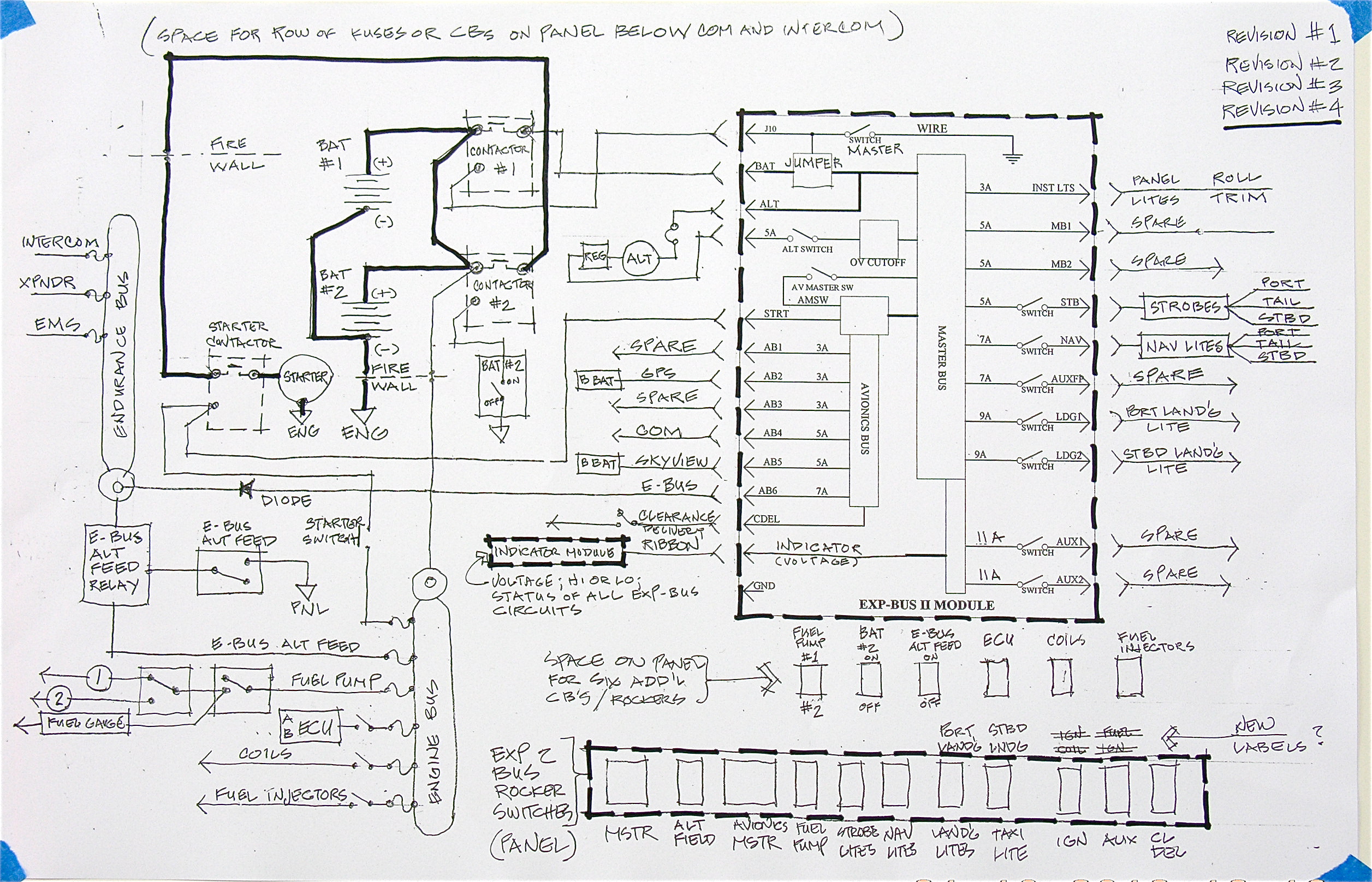
Attached are pixs of my instrument panel in its present state, and a proposed circuit diagram. The intention of the circuit diagram is to show:
- 2 batteries wired as one to allow staggered battery replacement to ensure one of the two is relatively new and in excellent condition,
- EXP Bus to function as the main power distribution bus, powered from Contactor #1 which is controlled by a master switch,
- Starter powered from Contactor #2 so that in-flight re-start is possible w/ master off,
- Engine Bus (always hot) wired directly to the "battery side" of Contactor #2
Note: For purposes of maintaining proper C of G, batteries and contactors will be aft of the cabin.
I'd be extraordinarily grateful for any comments, and particularly those which point out errors or weakness in the diagram or the conceptual framework which the diagram is intended to address.
Fred
| | - The Matronics AeroElectric-List Email Forum - | | | Use the List Feature Navigator to browse the many List utilities available such as the Email Subscriptions page, Archive Search & Download, 7-Day Browse, Chat, FAQ, Photoshare, and much more:
http://www.matronics.com/Navigator?AeroElectric-List |
|
| Description: |
|
| Filesize: |
46.19 KB |
| Viewed: |
9817 Time(s) |

|
| Description: |
|
| Filesize: |
77.81 KB |
| Viewed: |
9817 Time(s) |
|
| Description: |
|
| Filesize: |
1.81 MB |
| Viewed: |
9817 Time(s) |
|
|
|
| Back to top |
|
|
nuckolls.bob(at)aeroelect
Guest
|
| Posted: Mon Oct 21, 2013 3:45 pm Post subject: EXP 2 Bus workaround |
|
|
At 02:46 PM 10/21/2013, you wrote:
| Quote: | All,
I would first of all like to thank all posters who have
expanded my understanding of the issues I face as I proceed w/ the
wiring of my aircraft...you have already helped me immeasurably to
get to the revised (proposed) circuit diagram below.
|
I have pondered your project while plowing the asphalt between
here an Wichita for two round trips . . . and made some notes.
I'll be publishing my recommendations (as if it were my airplane)
in the next day or so. We'll be able to integrate the EXP-Bus with
some degree of grace.
I can find no reason to run two batteries in your project. The
disparity of endurance demands between the e-bus and engine-bus
leaves watt-seconds left over on the e-bus . . . which means
your panel is still lit after the engine quits.
My proposal will used the existing 'master' switch in the
legacy task. The avionics master will be come the e-bus
alternate feed. We'll create an engine bus very much like
the e-bus with a diode feed from the main bus for normal ops
and and a fat alternate feed from the battery like the
e-bus.
This means you can trade second battery and contactor weight
in for a larger main battery that will make your planning
and maintenance for Plan-B contingencies much simpler, longer
endurance and more reliable.
Tell me about your fuel pumps. What controls or limits their
pressure? By the way, what is the operating pressure for
the system?
Still wondering about A/B ECU boards. Can you leave them
powered up and simply select between A and B from the
control panel. Does an ECU NOT selected draw the same
current as the one presently selected?
Bob . . .
| | - The Matronics AeroElectric-List Email Forum - | | | Use the List Feature Navigator to browse the many List utilities available such as the Email Subscriptions page, Archive Search & Download, 7-Day Browse, Chat, FAQ, Photoshare, and much more:
http://www.matronics.com/Navigator?AeroElectric-List |
|
|
|
| Back to top |
|
|
Fred Klein
Joined: 26 Mar 2012
Posts: 503
|
| Posted: Mon Oct 21, 2013 8:59 pm Post subject: EXP 2 Bus workaround |
|
|
On Oct 21, 2013, at 4:45 PM, Robert L. Nuckolls, III wrote:
| Quote: | I can find no reason to run two batteries in your project. The
disparity of endurance demands between the e-bus and engine-bus
leaves watt-seconds left over on the e-bus . . . which means
your panel is still lit after the engine quits.
|
Bob...
I'm really surprised to here you say that...I've really bought into your rationale for having 2 batteries of equal size so they can be rotated out one at a time, raising the probability that one is always (relatively) new...as for my endurance bus, I'd love to add my COM to it. I think your rationale as I read it in the Connection is especially appropriate for an engine which can't rely upon mags.
'I'll get answers for your other questions tomorrow...
Thanks for your insights into my installation,
Fred
[quote][b]
| | - The Matronics AeroElectric-List Email Forum - | | | Use the List Feature Navigator to browse the many List utilities available such as the Email Subscriptions page, Archive Search & Download, 7-Day Browse, Chat, FAQ, Photoshare, and much more:
http://www.matronics.com/Navigator?AeroElectric-List |
|
|
|
| Back to top |
|
|
nuckolls.bob(at)aeroelect
Guest
|
| Posted: Tue Oct 22, 2013 6:04 am Post subject: EXP 2 Bus workaround |
|
|
At 11:57 PM 10/21/2013, you wrote:


On Oct 21, 2013, at 4:45 PM, Robert L. Nuckolls, III wrote:


  I can find no reason to run two batteries in your project. The

  disparity of endurance demands between the e-bus and engine-bus

  leaves watt-seconds left over on the e-bus . . . which means

  your panel is still lit after the engine quits.


Bob...


I'm really surprised to here you say that...I've really bought into

your rationale for having 2 batteries of equal size so they can be

rotated out one at a time, raising the probability  that one is

always (relatively) new...as for my endurance bus, I'd love to add my

COM to it. I think your rationale as I read it in the Connection is

especially appropriate for an engine which can't rely upon mags.

    I understand. It would help to review the history

    of the two-battery concept:


    The simplest, most reliable batteries are those which

    receive periodic critical attention, like pre-flight

    checks for fuel, oil, tire tread, controls, etc. The

    battery is this smooth plastic box hidden away out

    of sight and offers no observable data on it's

    state of charge or ability to even take a charge.

    Obviously, we cannot pre-flight a battery with the

    same level of confidence as pulling out the dipstick

    to check oil.


    But we do know that batteries tend to fail gracefully,

    sorta like the degradation of compression with the

    service time on an engine or tread wear with numbers

    of landings on tires. It is sufficient to check

    your compression every annual (~50 hrs for average

    light aircraft) or get out the tread wear gauge when

    the tires are "looking a bit skinny".


    Delving into the inner secrets of a battery is a

    process with more complexity and requiring more tools

    than peeking into a fuel tank or wiggling the stick

    to make sure controls are intact and free.


    The first driver for considering dual batteries was

    to eliminate or at least shift the cost of ownership

    for periodic polygraph testing of the battery. The

    idea was simply cycle a new battery into a pair

    of batteries every annual. The rationale for that

    philosophy was based on the owner/operator's willingness

    and dedication to the task of tracking the battery's

    condition.


    If you take the total cost of owning your airplane

    and divide by hours flown, you come up with some

    number. Rotating a new battery into the top of a pair

    each annual will add (cost-of-battery/hours-flown)

    to that other number. For many, the $time$ spent

    on doing a battery change-out was more attractive

    than taxation of $time$ to do the periodic battery

    polygraph.


    A second benefit of the dual battery architecture

    was that it clearly divided endurance calculations,

    planing and management into to camps. (1) engine

    and (2) everything else that influenced battery-only

    flying time. When I introduced the

    e-bus concept 20+ years ago, it was no big deal to

    craft a Plan-B wherein electrical system endurance

    exceeded fuel endurance.


    The people-paid-to-worry about airplanes tell us

    that for the most part, 30 minutes of battery-only

    endurance is enough. Perhaps so for the wizened ATP

    pilot with 10,000 hours and a host of successfully

    managed tense days in the cockpit. But for John Q

    fliver-flyer with 600 hours, no intensive training

    in airborne systems management and only flies

    50-100 hours a year . . . it's another matter

    entirely.


    Hence my personal design goals for seeking ways

    to assemble, maintain and operate systems with

    considerably more than 30 minutes of battery-only

    performance . . . preferably some number than

    exceeds duration of fuel aboard.


    So, in 4-5 hours of pondering your system here

    on the List and on the road, I've divided your

    battery only requirements into two piles. (1)

    no-options loads like keeping the fires behind

    the prop lit and (2) lighting up things on

    the panel that are most useful for continued

    cruising flight until a CONVENIENT, or better

    yet, airport of intended destination is in

    sight.


    As a renter of certified airplanes, my personal plan-B

    planning, maintenance and operation is necessarily

    limited to stuff I carry in my flight bag. In other

    words, from J3 to A36 Bonanza, I have no control

    over the airplane so I plan to get where I want

    to go wether the panel is lit up or not.


    Now, you've got an engine that we THINK takes

    about 10A to run. Getting one hour of endurance

    requires a single battery having about 20 a.h.

    capacity (when new) at the 20 hour rate. We know

    that failure to benefit from ALL of a battery's

    potential  energy is a function of the battery's internal

    resistance. So the proportion of energy tossed

    off internally at any given discharge rate is

    less if the battery is up-sized.


    Another consideration for your airplane is

    the value of partitioning system power into

    two tasks (1) truly essential - keeping the

    engine running and (2) optional - things on

    the panel.


    Okay, how does the Plan-B picture change if

    your airplane is fitting with one, larger battery.

    Several ways: First there is more incentive to

    KNOW the state of your battery's health. This

    means $time$ required for the periodic electrograph

    as a preventative maintenance policy on the

    airplane. But if you ran nothing but the

    engine during no-alternator-ops, then the larger

    single battery maximizes your endurance numbers

    into something far more comfortable than that

    30-minute thingy the paid-to-worry crowd is

    so comfortable with . . . but then, NONE of

    those folks are going to fly YOUR airplane.

    Next, with one battery, you have the option

    of turning OFF things that influence your

    endurance capabilities . . . especially if

    those capabilities are backed up by Plan-B1

    hardware in the flight bag. So if your desired

    destination is only an hour away, leave all

    that stuff on. But you have the option of getting

    2 hours plus endurance too.


    Finally, this line of reasoning offers a much

    simpler array of switches for which in-flight

    decisions must be made. It offers a relatively

    clean way to integrate the EXP-Bus into to

    final design.


    So armed with knowledge of battery condition,

    time to fly to an airport of convenience then

    you can simply choose what things on the panel

    will be lit up or shut down. Maybe you can

    go max-dark and fly hand-held until time

    for descent and approach whereupon you turn

    things back on. In this mode of flight, the

    only thing other than engine specific loads

    would be a voltmeter.


    Based on this recent line of reasoning, I'm

    wondering if elegance level Z-19 is really

    as cool as I thought when the drawing was

    crafted some years ago. It is perhaps and

    example of the "too soon we get old, too late

    we get smart" syndrome. But if that question

    in going to get answered, I doubt that it

    will happen more expeditiously than here

    on the List . . . and you (along with your

    airplane) may be the impetus for the effort.

   Bob . . .
| | - The Matronics AeroElectric-List Email Forum - | | | Use the List Feature Navigator to browse the many List utilities available such as the Email Subscriptions page, Archive Search & Download, 7-Day Browse, Chat, FAQ, Photoshare, and much more:
http://www.matronics.com/Navigator?AeroElectric-List |
|
|
|
| Back to top |
|
|
Fred Klein
Joined: 26 Mar 2012
Posts: 503
|
| Posted: Tue Oct 22, 2013 7:50 am Post subject: EXP 2 Bus workaround |
|
|
Bob,


I appreciate your circumspection in taking another look at your twin battery rationale as you stated it in the Connection. And I wrestle with what I see as inherent contradictions in our quest for both fail-safe redundancy and simplicity...i.e., the more redundancy, the more complexity...fail-safe redundancy - good...increased complexity - not so much.


A client of mine who certifies electrical and electronic systems for the big boys...I can't state his company's role or authority in the proper terminology...absolutely bemoans the aircraft industry's approach to solving problems in complex systems by adding another layer of complexity.


Fred
| | - The Matronics AeroElectric-List Email Forum - | | | Use the List Feature Navigator to browse the many List utilities available such as the Email Subscriptions page, Archive Search & Download, 7-Day Browse, Chat, FAQ, Photoshare, and much more:
http://www.matronics.com/Navigator?AeroElectric-List |
|
|
|
| Back to top |
|
|
nuckolls.bob(at)aeroelect
Guest
|
| Posted: Tue Oct 22, 2013 9:10 am Post subject: EXP 2 Bus workaround |
|
|
At 10:49 AM 10/22/2013, you wrote:
--> AeroElectric-List message posted by: Fred Klein <fklein(at)orcasonline.com>
Bob,
I appreciate your circumspection in taking another look at your twin battery rationale as you stated it in the Connection. And I wrestle with what I see as inherent contradictions in our quest for both fail-safe redundancy and simplicity...i.e., the more redundancy, the more complexity...fail-safe redundancy - good...increased complexity - not so much.
I think the seeds of the dual-battery tree
were planted by Lightspeed's early-on recommendations
for a second, diode maintained battery to insure
one source of power to a second ignition system.
A client of mine who certifies electrical and electronic systems for the big boys...I can't state his company's role or authority in the proper terminology...absolutely bemoans the aircraft industry's approach to solving problems in complex systems by adding another layer of complexity.
Sounds like a man who understands FMEA, MTBF
and the value of simplicity in the practical world
of human frailties.
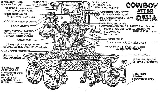
Unfortunately, a lot of public ignorance of
risks exploited by Hollywood and driven by
individuals-paid-to-worry . . .
[img]cid:.0[/img][/b]
Your friend sounds like a good resource to review
ideas in this . . . what do I call it . . .
critical review of what may have been an under-developed
idea. Not necessarily a BAD idea but not the elegant
solution.
I'll try to get a drawing crafted to clarify my
thoughts in a form suitable for fielding review by
thoughtful observers.
Bob . . .
| | - The Matronics AeroElectric-List Email Forum - | | | Use the List Feature Navigator to browse the many List utilities available such as the Email Subscriptions page, Archive Search & Download, 7-Day Browse, Chat, FAQ, Photoshare, and much more:
http://www.matronics.com/Navigator?AeroElectric-List |
|
| Description: |
|
| Filesize: |
187.14 KB |
| Viewed: |
9800 Time(s) |
|
|
|
| Back to top |
|
|
Fred Klein
Joined: 26 Mar 2012
Posts: 503
|
| Posted: Wed Oct 23, 2013 10:05 am Post subject: EXP 2 Bus workaround |
|
|
On Oct 21, 2013, at 4:45 PM, Robert L. Nuckolls, III wrote:
| Quote: | Still wondering about A/B ECU boards. Can you leave them
powered up and simply select between A and B from the
control panel. Does an ECU NOT selected draw the same
current as the one presently selected?
|
Bob,
ECU manual states:
There are separate power inputs for the A and B controllers. If your electrical system has a back up power bus you can connect the B controller to it. Otherwise tie both A and B power inputs together.
Tracy Crook just emailed:
Yes, both controllers draw current when either one is selected, Also, BOTH power inputs must be supplied with 12 volts when in operation.
Total Current draw is less than 1/2 amp.
If we proceed w/ an Engine Bus w/ alternate feed, it appears to me that both A and B would best be tied together.
Fred
[quote][b]
| | - The Matronics AeroElectric-List Email Forum - | | | Use the List Feature Navigator to browse the many List utilities available such as the Email Subscriptions page, Archive Search & Download, 7-Day Browse, Chat, FAQ, Photoshare, and much more:
http://www.matronics.com/Navigator?AeroElectric-List |
|
|
|
| Back to top |
|
|
Fred Klein
Joined: 26 Mar 2012
Posts: 503
|
| Posted: Wed Oct 23, 2013 10:14 am Post subject: EXP 2 Bus workaround |
|
|
Bob...you asked about my fuel pumps and pressures...


The fuel pressure at idle is 38 psi; at wot it rises to 43 psi.


The pressure is controlled by a regulator which sits on what my guy calls a "fuel log" which sets on the tops of the cylinders...I can provide photo if necessary.


Fred
| | - The Matronics AeroElectric-List Email Forum - | | | Use the List Feature Navigator to browse the many List utilities available such as the Email Subscriptions page, Archive Search & Download, 7-Day Browse, Chat, FAQ, Photoshare, and much more:
http://www.matronics.com/Navigator?AeroElectric-List |
|
|
|
| Back to top |
|
|
Fred Klein
Joined: 26 Mar 2012
Posts: 503
|
| Posted: Wed Oct 23, 2013 10:51 am Post subject: EXP 2 Bus workaround |
|
|
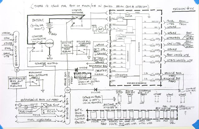
Bob...this latest iteration of diagram is my effort, striving for elegance, to incorporate your suggestions which I present as follows:

- Wire the engine bus via a diode feed from the 2, 11amp AUX circuits on the EXP Bus; provide an alternate feed from the battery via an "Engine Bus Alternate Feed Relay".

- Wire the endurance bus via a diode feed from a 7 amp circuit on the EXP Bus; provide an alternate feed from the engine bus via an "Endurance Bus Alternate Feed Relay".

- Regarding the re-wiring and re-labeling of some of the EXP Bus rockers, I've deviated from your suggestions after considering the following rationale and thinking about having a simple organization if things go south:

		Let the row of EXP Bus rockers serve for normal ops; i.e., power up the ECU, the fuel injectors, and the coils using the 3 rockers furthest to the left, currently labeled

"I GN", "AUX", and "Clrnc Del"...(for my anticipated ops, clearance delivery will be rarely used).


		Let the space above the EXP Bus be for switches used during emergencies; i.e., switch from fuel pump #1 to fuel pump #2; switch engine bus to alternate feed, and endurance bus to alternate feed (both feeds direct to battery, if EXP Bus or alternator go out.

- One battery and master contactor are shown, but I'm inclined to leave open for now the option for dual batteries and rotating out one of them periodically.

All comments most appreciated.

Fred

[img]cid:13F273D5-460E-42FE-917A-347EBD3AD8C6[/img]


 [img]cid:51CD48EE-C6FF-4A77-987C-12CE77891CEA[/img]
| | - The Matronics AeroElectric-List Email Forum - | | | Use the List Feature Navigator to browse the many List utilities available such as the Email Subscriptions page, Archive Search & Download, 7-Day Browse, Chat, FAQ, Photoshare, and much more:
http://www.matronics.com/Navigator?AeroElectric-List |
|
| Description: |
|
| Filesize: |
69.6 KB |
| Viewed: |
9790 Time(s) |
|
| Description: |
|
| Filesize: |
46.19 KB |
| Viewed: |
9790 Time(s) |
|
|
|
| Back to top |
|
|
nuckolls.bob(at)aeroelect
Guest
|
| Posted: Wed Oct 23, 2013 3:42 pm Post subject: EXP 2 Bus workaround |
|
|
At 01:50 PM 10/23/2013, you wrote:
| Quote: | Bob...this latest iteration of diagram is my effort, striving for
elegance, to incorporate your suggestions which I present as follows:
- Wire the engine bus via a diode feed from the 2, 11amp AUX
circuits on the EXP Bus; provide an alternate feed from the battery
via an "Engine Bus Alternate Feed Relay".
|
Okay, getting closer.
(1) Recommend you take the engine bus normal feedpath directly
from the main bus through the diode. A normal Engine ON/OFF
switch in this path seems to make sense see (6).
(2) add 30A maxi fuse in series with Engine Bus Alternate
Feed path and being engine power forward on 10AWG wire.
(3) Take E-Bus alternate feed directly from the battery on
it's own 7A fuse and 14AWG wire . . . 10A fuse if determined
necessary later.
(4) Go to solid state relays for e-bus and E-bus alternate
feeds, either Eric's or ours.
(5) Run #2 fuel pump from main bus through polyfuse and
EXP Bus switch.
(6) I see no value in having separate switches for
injectors, coils, normal pump or ECU feed. One switch
in normal feed path for normal engine ops, one switch
to control alternate feed path. When and why would you
ever operate one of these switches independently of
the others. Two ways to power engine . . . normal and
alternate.
(7) Suggest separate fuses for each injector and coil
assuming engine produces some useable power with any
one fuse open.
( Starter can control from main bus. Starter can control from main bus.
(9) Turn existing avionics bus into e-bus, convert
old avionics master into alternate feed path control
switch. Normal feed path comes from main bus through
diode.
(10) You speak to "room for breakers/fuses on panel"
suggest these be out of sight, of reach.
Bob . . .
| | - The Matronics AeroElectric-List Email Forum - | | | Use the List Feature Navigator to browse the many List utilities available such as the Email Subscriptions page, Archive Search & Download, 7-Day Browse, Chat, FAQ, Photoshare, and much more:
http://www.matronics.com/Navigator?AeroElectric-List |
|
|
|
| Back to top |
|
|
Fred Klein
Joined: 26 Mar 2012
Posts: 503
|
| Posted: Wed Oct 23, 2013 7:36 pm Post subject: EXP 2 Bus workaround |
|
|
On Oct 23, 2013, at 5:03 PM, Bill Bradburry wrote:
| Quote: | What is the switch Clrnc Del used for in the normal install? Is this a second avionics master to use to get a clearance prior to starting the engine??
|
Bill...I suppose you could call it that...the Clearance Delivery is on a "keep alive" 3 amp circuit w/ its own on/off switch intended for communication w/ tower w/o turning on your whole panel prior to engine start up...Fred
[quote][b]
| | - The Matronics AeroElectric-List Email Forum - | | | Use the List Feature Navigator to browse the many List utilities available such as the Email Subscriptions page, Archive Search & Download, 7-Day Browse, Chat, FAQ, Photoshare, and much more:
http://www.matronics.com/Navigator?AeroElectric-List |
|
|
|
| Back to top |
|
|
user9253
Joined: 28 Mar 2008
Posts: 1969
Location: Riley TWP Michigan
|
| Posted: Thu Oct 24, 2013 10:34 am Post subject: Re: EXP 2 Bus workaround |
|
|
Looking at the EXP 2 Bus Installation Manual

http://support.anywheremap.net/pdfs/EXP2-C.pdf

Page 15 has a simplified schematic.  In the lower right hand corner are 2 diodes, D10 and D12, that can power the engine.  The diodes are powered by two separate circuits: the MAIN BUS and the BACKUP BUS which can get its power directly from the battery through J31.

  The problem is trying to convert the avionics bus into an endurance bus.  There does not appear to be an avionics mechanical relay.  It looks like a solid state relay with an ON-OFF input and a START DISABLE input.  Without having the board in hand, it is hard to say how to bypass this device with a diode.  Another problem is how to feed the avionics bus with a second power input from an E-bus relay.

  Notice in the upper right hand corner is diode D3.  What is that for?  When would current ever want to flow in the opposite direction?  The only thing that I can think of is that it is a misguided attempt to prevent voltage spikes from the master contactor coil.  But any induced current will flow with the diode, not in the opposite direction.  Am I overlooking something?

Joe
| | - The Matronics AeroElectric-List Email Forum - | | | Use the List Feature Navigator to browse the many List utilities available such as the Email Subscriptions page, Archive Search & Download, 7-Day Browse, Chat, FAQ, Photoshare, and much more:
http://www.matronics.com/Navigator?AeroElectric-List |
|
_________________
Joe Gores |
|
| Back to top |
|
|
Fred Klein
Joined: 26 Mar 2012
Posts: 503
|
| Posted: Thu Oct 24, 2013 2:10 pm Post subject: EXP 2 Bus workaround |
|
|
Joe...see indents below within your text...Fred
On Oct 24, 2013, at 11:34 AM, user9253 wrote:
| Quote: |
Looking at the EXP 2 Bus Installation Manual
http://support.anywheremap.net/pdfs/EXP2-C.pdf
Page 15 has a simplified schematic. In the lower right hand corner are 2 diodes, D10 and D12, that can power the engine. The diodes are powered by two separate circuits: the MAIN BUS and the BACKUP BUS which can get its power directly from the battery through J31.
|
The "simplified schematic" on p. 15 shows the optional back up battery diodes; this is a factory mod which I do not have. My EXP is better described by the schematic on p. 13 (Typical install w/ Ext. Solenoid...factory supplied jumper replaces the Master Relay K1)...however, the AUX1 and AUX2 circuits are mislabled and are 11 amps, not 7 amps as shown.
| Quote: | The problem is trying to convert the avionics bus into an endurance bus. There does not appear to be an avionics mechanical relay. It looks like a solid state relay with an ON-OFF input and a START DISABLE input. Without having the board in hand, it is hard to say how to bypass this device with a diode. Another problem is how to feed the avionics bus with a second power input from an E-bus relay.
|
I am loath to alter the innards of the EXP, other than perhaps re-lable and re-purpose a couple of the rocker switches and wiring them accordingly. My latest proposed circuit diagram shows a separate E-bus fed thru a diode from a 7 amp circuit off the EXP Avionics bus, with an alternate feed thru a relay from the engine bus. I'm content to allow the Avionics Bus to remain as is, noting that both GPS and Skyview do not move to the E-bus as they both have stand alone back up batteries. It's no accident that this thread is named "workaround".
| Quote: | Notice in the upper right hand corner is diode D3. What is that for? When would current ever want to flow in the opposite direction? The only thing that I can think of is that it is a misguided attempt to prevent voltage spikes from the master contactor coil. But any induced current will flow with the diode, not in the opposite direction. Am I overlooking something?
|
These things I cannot commentt on...
| | - The Matronics AeroElectric-List Email Forum - | | | Use the List Feature Navigator to browse the many List utilities available such as the Email Subscriptions page, Archive Search & Download, 7-Day Browse, Chat, FAQ, Photoshare, and much more:
http://www.matronics.com/Navigator?AeroElectric-List |
|
|
|
| Back to top |
|
|
nuckolls.bob(at)aeroelect
Guest
|
| Posted: Fri Oct 25, 2013 5:32 am Post subject: EXP 2 Bus workaround |
|
|
Attached are the preliminary sketches for my current

thoughts on an architecture for single battery, single

alternator, electrically dependent engine. This line of

thinking is being developed as an preferred alternative

to Z-19.


This architecture has roots in Z-11 Three-Bus structure

with the addition of a Motive Power Bus (engine). With

the term E-bus already in legacy use, the MP-Bus terminology

offers a stand-out label that avoids confusion.


The major difference is the addition of the MP-bus having

normal feedpath from the main bus, alternate feedpath from

the battery . . . same as the E-Bus except BOTH pathways

have panel mounted switches. The e-bus is always hot any

time the main bus is hot, but the MP-Bus as power to the

engine needs to be controlled through both pathways.


I'm thinking that the EXP-bus can be folded into this

architecture by conversion of battery switch to DC master

and take alternator field through second pole. Convert

the 'avionice master' Engine A. Use switch between the

big red rockers as e-bus alternate feed. Switch to right

of Engine A is Engine B.


Old avionics bus becomes e-bus. Add fuse-block with

sufficient slots to accommodate MP-Bus loads.


Solid state relays in the alternate feed paths is

an option. Nothing wrong with the legacy automotive

plastic cube relays here but the DO draw about 100

mA each. Two relays in the battery only mode consumes

as much energy as another accessory . . . solid state

relays will consume a milliamp or so.  That's a decision

that is not germane to current identification of loads

and shuffling them to the right bus.


Fred, if you would make a list of how the various

electrical loads would be distributed along these four

busses, I can move forward with a refinement of the

idea specific to your airplane. Don't worry about circuit

protection or wire sizing . . . just a list of everything

that gets a protected feeder and which bus you would

attach it to.


The next phase of the EXP-Bus workaround involves a

head-count of protected load-taps from existing e-bua

and main bus structures on the EXP-Bus assembly . . .

and distributing those load-taps amongst proposed

electro-whizzies. The MP-Bus is easy since it's an

external addition and not limited as to numbers of

load taps.


The relative risk factors for this architecture are

driven by the same factors that have been part-and-parcel

of owning and operating an airplane of any genre' whether

OBAM or TC.


KNOW YOUR BATTERY and it's EXPECTED DUTIES to meet

DESIGN GOALS for battery only operations. Then maintain

that capability as religiously as you change oil, tires

or use safety wire on prop bolts.


The two-battery band-aid is, perhaps, not as great

a risk mitigation as we once thought. This has been

a good exercise in the sifting of bits and pieces.

Critical review solicited and welcomed.


   Bob . . .
| | - The Matronics AeroElectric-List Email Forum - | | | Use the List Feature Navigator to browse the many List utilities available such as the Email Subscriptions page, Archive Search & Download, 7-Day Browse, Chat, FAQ, Photoshare, and much more:
http://www.matronics.com/Navigator?AeroElectric-List |
|
| Description: |
|

Download |
| Filename: |
Z-08_Full.pdf |
| Filesize: |
335.26 KB |
| Downloaded: |
340 Time(s) |
| Description: |
|
Download |
| Filename: |
Z-08_Excerpt.pdf |
| Filesize: |
204.02 KB |
| Downloaded: |
307 Time(s) |
|
|
| Back to top |
|
|
Fred Klein
Joined: 26 Mar 2012
Posts: 503
|
| Posted: Fri Oct 25, 2013 4:36 pm Post subject: EXP 2 Bus workaround |
|
|
Bob, thank you for your analysis and recommendations...they greatly enhance my learning experience here...please see my indents below...I have additional comments (later) on your posted circuit diagram of this morning...Fred
On Oct 23, 2013, at 4:41 PM, Robert L. Nuckolls, III wrote:
| Quote: | Okay, getting closer.
(1) Recommend you take the engine bus normal feedpath directly
from the main bus through the diode. A normal Engine ON/OFF
switch in this path seems to make sense see (6).
|
I don't understand how I might "take the engine bus normal feedpath directly
from the main bus through the diode." It seems to imply to me that I poke around on the circuit board and find a place to attach a wire. I thought my proposal to tap the existing two 11 amp AUX circuits with a fast-on spade or two would be a rather elegant way to use what's available. (See my comments on your item (6) below.)
| Quote: | (2) add 30A maxi fuse in series with Engine Bus Alternate
Feed path and being engine power forward on 10AWG wire.
|
OK...straightforward enough...
| Quote: |
(3) Take E-Bus alternate feed directly from the battery on
it's own 7A fuse and 14AWG wire . . . 10A fuse if determined
necessary later.
|
I can do that; this adds another wire forward from rear battery to bus...What's the advantage of doing this rather than using a short wire to the Engine (MP) bus, as long as the total E-bus + MP bus loads can be handled by the EXP Bus circuit from which power is being drawn? Normally (I believe the) E-bus alternate feed will ONLY be activated in conjunction w/ the Engine (MP) bus alternate feed (sized accordingly) is activated.
| Quote: | (4) Go to solid state relays for e-bus and E-bus alternate
feeds, either Eric's or ours.
|
OK
| Quote: | (5) Run #2 fuel pump from main bus through polyfuse and
EXP Bus switch.
|
Let's talk about the 2 fuel pumps for a MPEFI engine. Unlike w/ carb engines, the 2nd pump is not used as a boost pump. I'm advised that w/ a MPEFI engine, one never wants to run more than ONE pump at a time due to excessive pressure in the system.
This is why I've been showing 2 switches in series...the first switch powers up a single fuel pump...whether that is pump #1 or pump #2 depends on the second switch. The reason for two fuel pumps is to ensure fuel flow in the event of either a pump failure or a clogged filter. These events can occur regardless of where the elec power is coming from. I say it's essential that BOTH pumps can be energized either thru the EXP Bus or the Engine (MP) bus alternate feed.
I believe your point (5) misconstrues the purpose of dual pumps in a MPEFI engine. What am I missing?
| Quote: | (6) I see no value in having separate switches for
injectors, coils, normal pump or ECU feed. One switch
in normal feed path for normal engine ops, one switch
to control alternate feed path. When and why would you
ever operate one of these switches independently of
the others. Two ways to power engine . . . normal and
alternate.
|
On reflection, I understand (finally)...a single switch it is.
| Quote: |
(7) Suggest separate fuses for each injector and coil
assuming engine produces some useable power with any
one fuse open.
|
This sounds like a novel idea...I'm wondering if anyone's ever done this before?.. how much increased complexity is entailed?...and whether or not historical rates of injector and coil failures suggest that this would be prudent?
| Quote: | ( Starter can control from main bus.
|
True...and...w/ my particular combination of engine, reduction ratio, propeller, and aircraft performance envelope, although I THINK that with engine out, prop would windmill sufficient to restart engine, if Master switch was OFF, I'd like to be able to spin the starter...that was the INTENT of what the diagram shows...What do you think?...I'm unsure as to whether or not the wiring diagram allows for that to happen.
| Quote: | (9) Turn existing avionics bus into e-bus, convert
old avionics master into alternate feed path control
switch. Normal feed path comes from main bus through
diode.
|
I'm completely in the dark as to my understanding of what physical changes must be made to the EXP Bus to accomplish this.
| Quote: |
(10) You speak to "room for breakers/fuses on panel"
suggest these be out of sight, of reach.
|
That would be possible of course, though if CBs are used, questionable. I'm presuming that you want them out of sight to reduce workload in an emergency, and to avoid possibly exacerbating conditions by resetting popped CBs...is that so?
| | - The Matronics AeroElectric-List Email Forum - | | | Use the List Feature Navigator to browse the many List utilities available such as the Email Subscriptions page, Archive Search & Download, 7-Day Browse, Chat, FAQ, Photoshare, and much more:
http://www.matronics.com/Navigator?AeroElectric-List |
|
|
|
| Back to top |
|
|
|
|
You cannot post new topics in this forum
You cannot reply to topics in this forum
You cannot edit your posts in this forum
You cannot delete your posts in this forum
You cannot vote in polls in this forum
You cannot attach files in this forum
You can download files in this forum
|
Powered by phpBB © 2001, 2005 phpBB Group
|

